Note: Descriptions are shown in the official language in which they were submitted.
1~7~ ~5~
ARTICLES COMPRISING SHAPED WOVEN FA~RICS
The present invention relates to heat-activatable
shaped hollow woven fabrics, where the shape is inherent
in the weave rather than produced by sewing or otherwise
joining together simple sheets. Heat-activation may
result in for example dimensional recovery, an increase in
rigidity caused for example by curing, or adhesive activa-
tion causing impermeabilty or bonding to a substrate.
Shaped hollow fabrics have many uses, but the
present specification will deal primarily with those
fabrics useful in the energy, telecommunications,
electronics, pipeline and related industries. For
example, substrates of complex shape may require inter-
connéction, mechanical fixing, environmental protection
or electrical screening etc. In each of those examples
some form of encapsulation of the substrate may be
required and a correspondence in size and shape between
the substrate and its covering will be desirable. Hence
the reason for the shaping and the hollow configuration.
We have found that shaped fabrics are for some uses
preferable over moulded parts due to their excellent
creep performance, high strength and abrasion resistance
and lack o~ tendency to split once cut or scored, and
due to the in-line manufacturing techniques available
for their production.
Hitherto hollow articles for encapsulation in the
fields with which we are primarily concerned have almost
always consisted of moulded material, although
knitting has of course been used to make shaped articles
such as gloves. For example articles such as boots (an
article for encapsulation having generally about two
outlets arranged at an angle to one one another), end
caps, transitions and udders (an article for encapsulation
having generally three or more outlets towards one end
,
~27'~
thereof) have been made from plastics materials by
injection, compression or transfer moulding. These
articles may be used to seal joints between cables or
between pipes and to seal terminations of cables etc.
The fact that such hollow articles are preferably
designed with a specific substrate in mind means that an
excellent seal can be achieved resulting in good performance.
The disadvantage, however, is that they are expensive
to produce, especially in small quantities, because a
mould has to be made for each design . Also, it may be
desirable to provide an internal coating of an adhesive
(for environmental sealing) or a metal (for electro-
magnetic screening) within the hollow article, and such
: . ., .. , ... , , .................. - .
coating may be extremely difficult to carry out accurately.
We have discovered that these problems may be
overcome i~ the hollow article is made by weaving.
Thus, the present invention provides a heat-activatable
article comprising a fabric having an angled or
branched hollow region woven therein.
By angled or branched we exclude simple hollow
~ regions such as cylinders or others of infinite rotational
; symmetry (neglecting the fact that any such hollow will
be generally ~lattened) which can be made easily by
other techniques.
The article is preferably heat-activatable by virtue
of the fabric being woven from heat-recoverable fibres,
heat-curable fibres or heat-activatable adhesive
(heat-softenable or hot-melt) fibres. Two or more of
these may be combined. Alternatively, or additionally,
heat-activation may result from insertion or addition
of another material after weaving.
Preferably the fabric forms at least part of an
article for screening an electrical component, the
fabric having as a component thereof fibres comprising
an electrically conductive material. The article preferably
has means for electrically terminating said fibres for
example to an adjacent screen. The article after
recovery preferably has a surface transfer impedance of
5 ohm/m or less, measured over a frequency of from 1-50
MHz. Alternatively, the article may be used to provide
environmental protection. A further use is as a struc-
tural article for example for use as a supprot or as a
part of a larger article. In this case heat-activation
may usefully comprise heat-curing to produce an
increase in rigidity.
The configuration of the hollow region may be altered at
will simply by altering the pattening program on the
loom. The work involved in altering the weave design
produced by a loom may be contrasted with the work
involved in producing a new mould for, say, an injection
moulding machine. The second major advantage of the
invention over the prior art is that the various functions
required of the finished article may result from the
weaving together of many different fibres, each the best
for a single specific function. Thus, environmental
protection may be provided by a hollow T or other
r branch-piece woven from fibres of high density polyethy-
lene for mechanical strength and from fibres of a
polyamide which can be caused to melt to provide a
impervious adhesive layer. The weave design may be
chosen such that the polyethylene appears primarily on
the outside of the article and the polyamide adhesive
appears primarily on the inside. This is analogous to
an internally coated moulded part, but it is significantly
easier to produce reliably and with accuracy, especially
as regards the amount and positioning of the adhesive.
Ll _
One property that is important in the art of
environmental encapsulation and connection is dimensional-
recoverability, by means of which an article initially
of one size or shape can be made to change its dimensions.
Thus a hollow article can be manufactured, for example
oversized, such that it can be installed easily. After
appropriate treatment it fits tightly. Although
recoverability can allow reasonable tolerances in
manufacture, this is generally only as regards size, and
products still must be made of a particular topology.
Recoverable articles generally recover on suitable
treatment, such as heating, towards an original shape
from which they have previously been deformed b~t the
term recoverable as used herein includes an article
which adopts a new configuration even if it has not
previously been deformed. The fabric of the present
invention may be recoverable in order that it may be
easily installed, and recoverability is preferably
included by weaving recoverable fibres rather than by
deforming, for example stretching, the woven fabric. As
applied to the fabric, therefore, the term recoverable
relates to the adoption of a new configuration in the
absence of previous deformation.
The present invention also provides a method of
protecting or holding a substrate comprising a cable or
cable splice which comprises surrounding the substrate
by a heat-activatable article comprising a fabric having
a hollow region woven therein, which hollow
oorrespondes to the configuration of the substrate.
The fabric is preferably dimensionally-recoverable,
and the hollow may be angled or branched. Recoverabilty
may allow the article to grip the substrate thereby
holding it together, protecting it and/or attaching it
to some other article.
274~51
The provision of recoverability by weaving recoverable
fibres leads to a further significant advantage over
the prior art moulding methods. In the prior art such
hollow articles required deformation, for example, by
expansion after their formation. It is not of course
possible to produce, say, a heat shrinkable moulded part
directly from a heat-shrink~ble material by a thermoforming
technique. This problem is avoided by weaving , since
shape results from the pattening program rather than
from a thermoforming process.
A few general remarks about recoverable articles may
usefully be made. In their most common form, such
articles comprise a heat-shrinkable sleeve made from a
. , . . . . , , . , . . , . , -, ...
polymeric material exhibiting the property of elastic or
plastic memory as described, for example, in U.S.
Patents 2,027,962; 3,086,242 and 3,597,372. As is made
clear in, for example, U.S. Patent 2,027,962, the
original dimensionally heat-stable form may be a transient
form in a continuous process in which, for example, an
extruded tube is expanded, whilst hot, to a dimensionally
heat-unstable form but, in other applications, a preformed
dimensionally heat stable article is deformed to a
dimensionally heat-unstable form in a separate stage.
In the present case, fibres may become recoverable
merely as a result of an extrusion step, but recovery or
further recovery may be induced by subsequent stretching
for example after initial take-up.
In the production of heat-recoverable articles,
the polymeric material may be cross-linked at any stage
in the production of the article that will enhance the
desired dimensional recoverability. One manner of
producing a heat-recoverable article comprises shaping
the polymeric material into the desired heat-stable form,
subsequently cross-linking the polymeric material,
~7~
-- 6 --
heating the article to a temperature above the crystalline
melting point or, for amorphous materials the softening
point, as the case may be, of the polymer, deforming the
article and cooling the article whilst in the deformed
state so that the deformed state of the article is
retained. In use, since the deformed state of the
article is heat-unstable, application of heat will cause
the article to assume its original heat-stable shape.
In other articles, as described, for example, in
British Patent 1,440,524, an elastomeric member such as
an outer tubular member is held in a stretched state by
a second member, such as an inner tubular member, which9
upon heating, weakens and thus allows the elastomeric
member to récover.
The fabric is preferably made by at least notionally
splitting a zone of warp fibres into at least a first
group of fibres and a second group of fibres, such that
the fibres of the first group alternate regularly or
irregularly with those of the second group;
inserting weft fibres (a) to interlace warp fibres
of the first group but not of the second group; and
inserting weft fibres (b) to interlace warp fibres
of the second group but not of the first group.
Weft fibres (a) may alternate with weft fibres
(b) to produce a plain weave or two or more of (a) and/or
(b) may be grouped together to produce weaves of other
design.
A single shuttle, or other feed system of the weft
fibres, or two or more shuttles may be provided, for
example one for each layer or ply of fabric.
5 ~
The result of this is to produce two layers or
plies of woven fabric9 one above the other. Since a hollow
article rather than two unconnected lengths of fabric is
required, the weft fibres (a) and the weft fibres (b)
may both interlace a certain number of warp fibres at
either edge of the above-mentioned zone. Alternatively,
or additionally, a knitted stitch may be provided joining
together the longitudinal edges of the fabric, as will
result for example from use of a needle insertion narrow
fabric loom. A further technique, applicable
to the use of a shuttle loom, is to use a con-
tinuous weft by circular weaving. The number of
warp fibres that constitute the first and second
groups is made to varY across the warp direction as
weaving proceeds such that the hollow becomes angu-
lar or branched, if required. The result of such a
variation may be to make an angle or branch in the
plane of the fabric. Alternatively, or additionally,
the number of groups of fibres constituting the zone may
be made to change, for example from two to three (or
three to two) as weaving progresses thereby causing the
number of layers of fabric to increase from two to
three. The result of this is the production of a
generally blind, hollow branch-off in the thickness
of the fabric. The number of layers of fabric may
be four (or more) thereby producing two hollow
regions in the thickness of the fabric which are
separable. Four layers will require two edge joins
and this may be done using, for example, a narrow
fabric needle loom having two weft insertion needles and
associated knitting needles at the edges.
The splitting of the first and second (and optionally
other) groups was said above to be at least notional.
These groups may in fact be split such that one group is
`` ~Z7~
held above the other on the loom. Then, when a weft
fibre is about to be inserted, the appropriate group is
brought into allgnment with the weft fibre, and warp
fibres of that group are then lifted, depressed or
unmoved as appropriate to produce the desired weave
pattern in that group. A loom could of course be used
that could insert weft fibres at different positions
corresponding to the split first and second groups. We
prefer, however, that the splitting is indeed notional.
By this we mean that the first and second groups are
merely classifications and that they are never physically
separated all of one group from all of the other group.
Weaving could proceed as follows. At first all of the
warp fibres (those in the above-mentioned zone and those
of a border either side of the zone) are mutually
level. When a weft insertion is to be made into the
first group, all of the second group and certain of the
first group (every other warp in the case of a plain
weave etc.) and certain of the border fibres are lifted.
The next weft insertion may also be for the first group,
in which case the second group of warp fibres would
remain lifted but a different set of first group and
border fibres would be lifted. The next weft insertion
may be for the second group in which case all of the
first group and certain of the second group and border
fibres would be lifted.
If` this general process were continued, a weave
incorporating a cylindrical hollow region would result.
However, if as mentioned above, the size of the two
groups which effectively remain distinct is altered as
weaving progresses then a hollow region bound by edges
oblique to the warp direction will result. In this way
an angular (which includes a curved) hollow region
can be made. Also a branched hollow region can be made
~2~7~
by increasing the width of the zone and at some stage
causing weft fibres to join the first and second groups
together in the middle of the zone, thus breaking the
zone into two zones which may move steadily apart as
weaving progresses This would produce a branch-off
having a Y shape.
So far nothing has been said about the weave
design except as regards the localized provision of two
or more layers of fabric which become one layer outside
a specified zone. Any suitable weave may be employed,
for example plain, matt (or basket), twill, broken twill,
satin, sateen, leno, hop sack, sack and various weave
combinations, in single or mutliple ply weaves. The
weave design may be uniform over the whole fabric or
different weave designs may be employed at different
parts, for example over the zone and at the borders. An
advantage of any of these weaves is that by employing
different fibres as the warp and weft, or by employing
zones of different fibres as each of the warp and weft,
a hollow article with anisotropic or localized properties
may be produced. The weave density and fibre thickness
will depend on the intended use of the hollow article.
For a typical screening application we prefer for each
ply recoverable picks of from 0.1-1.Omm, especially
about 0.3mm (monofilament diameters) and from 2-24,
especially 4-16, more especially 6-12 picks/cm. The
warp is preferably of a conductive material, for
exarnple about 32 awg wire at 20-40, especially about 28
ends/cm. In general, a broad range of 6-120 ends/cm
will cover most situations.
Particularly where the hollow article is to be
used for screening, it may be desirable to increase the
weft density (in the case of a conductive warp) to
reduce the extent of opening up of the warp fibres on
~llZ~4~S~L
- 10 -
installation. It may also be desirable to increase the
amount of conductive (or other) material by employing
multi-plies instead of a single ply as each layer o~ the
fabric. This will allow greater recovery for a given
quantity of non-recoverable conductive material.
It may be particularly desirable to produce a hollow
article with substantially undirectional dimensional
recoverability, particularly where the hollow comprises
generally cylindrical parts whose length remains constant
on circumferential shrinkage. This may be achieved by
employing a dimensionally-stable warp and a dimensionally-
recoverable weft. Where the hollow article has a branch
that runs obliquely to the warp direction, such as a
Y-piece has, then in general recovery of the oblique
arms may have a longitudinal component and a circumferential
component. The unwanted recovery can be quite
small especially if the angle between the arms is small
and it can be localized by employing short oblique arms
followed by extensions in the warp direction.
One way of ensuring that recovery is substantially
only circumPerential in a branching hollow region,
is to design the hollow regions only in the warp direc-
tion and weft direction (ie not oblique), these regions
being joined by right angle bends. The hollow region
running along the warp direction can be circurnferen-
tially recoverable by using recoverable fibres only
in the weft direction when the hollow region is to run
in the weft direction (the technique described above for
making the hollow region still applies, only the rela-
tive width and length being different) a dimensionally
stable weft may be used, and recoverable warp fibres
brought into play, replacing previously used stable warp
74~LS~
-- 1 1 --
fibres unless the hollow fabric is now being generated
over a fresh part of the loom. Where recoverable warp
fibres replace stable fibres the two types may both be
present on the warp beam or other warp feed, arranged
alternately in a similar way to that described above for
the first and second groups of warp fibres in the zone
where the hollow region is generated. It is thus not
necessary to stop the loom and change the fibres, and
this technique may be employed in the weaving of simple
non-hollow sheets. In such a situation the warp fibres
may be classified as of three types; firstly non reco-
verable fibres which may be used to form a border
behind and in front of the weft-extending hollow,
secondly recoverable fibres that will form, sayt the
upper layer of the hollow region, and thirdly reco-
verable fibres that will form the lower layers of the
hollow region. These three sets of fibres may alternate
regu].arly or irregularly across the warp beam. This
technique may be used to make a fabric having merely
different extents of recovery in the warp direction.
The invention therefore further provides a recoverable
woven fabric having recovery localized along, or different
extents of recovery along,the warp direction.
The term "fibre" as used herein includes filaments
e.g. monofilaments or multifilaments, and also staple
fibre yarns, tows, wires and tapes. The fabrics preferably
employ the heat shrinkable fibres in the form of filaments,
especially monofilaments, and particularly cross-linked
monofilaments.
Heat-recoverable fibres used in the fabric of the
invention preferably have a minimum recovery stress of
10-1 MPa, more preferably 5 X 10⁻¹ and usually at
least lMPa at a ternperature above the transition
temperature of the fibres. There is in theory no upper
limit of recovery stress, but in practice 200 MPa and
more usually 100 MPa is the highest figure normally
achievable with polymeric fibres.
The fibres are preferably formed from a polymeric
heat-recoverable material. By the recovery temperature
of polymeric heat-recoverable materials is meant that
temperature at which the recovery of the polymeric
material will go substantially to completion. In
general, the recovery temperature will be the crystalline
melting transition temperature if the polymer is crystalline
or the glass transition temperature if the polymer is
amorphous.
.. . . . ..
The heat-recoverable fibres are preferably formed
from a polymeric material that imparts good physical
properties and, in particular, good creep resistance to
the fibres. Olefin polymers such as polyethylene, and
ethylene copolymers, polyvinylidene fluoride, polyamides,
polyesters, acrylic polymers and other polymers may be
employed and preferably those that are capable of being
cross-linked. A particularly preferred polymeric
material for the fibres is based on polyethylene having
a density of from 0.94 to 0.97 gm/cc, a weight average
molecular weight Mw of from 80 X 103 to 200 X 103
and a number average molecu].ar weight Mn of from 15 X
103 to 30 X 103.
Preferably the recovery temperature of the fibres is
60OC or more, most preferably from 80C to 250C, such
as, for example, 120 - 150C.
We prefer that recoverable fibres used have a
recovery percentage (change expressed as a percentage of
the old dimension) of at least 30, particularly at least
~Z79~S~
- 13
50, preferably at least 75, especially at least 80,
particularly at least 90. Depending on the weave design
and other ~`actors, fabric made from recoverable fibres
will have a lower recovery percentage than that of its
free fibres, and we prefer fabrics of at least 20%,
particularly at least 50%, especially at least 60~, most
preferably at least 66~ recovery. Where the fabric is
laminated or otherwise treated to make an impervious or
composite structure, recovery will again be reduced and
preferred figures are at least 20~, especially at least
40~, preferably at least 50~.
When the fibre is cross-linked by irradiation
it is convenient to incorporate the cross-linking step
into manufacture of the fibres. The fibre can be
extruded, stretched at a temperature below its melting
temperature, preferably by an amount of from 800 to 2000
~, then subjected to irradiation to effect cross-linking.
An alternative way of rnaking the fibre is to extrude the
fibre, irradiate to cross-link, then heat the fibre,
preferably to above its melting temperature, stretching
the fibre, and then cooling the stretched fibre. High
density polyethylene fibres are preferably irradiated
with a dose of from about 5 to about 35 megarads,
preferably from about 5 to about 25 megarads, especially
from 10 to about 18 megarads. U.sually the gel content
of the cross-linked fibre is greater than 20%, preferably
greater than 30%, most preferably greater than 40%. In
practice, gel contents greater than 90% are not easily
achievable. Fibres produced in this way can have a high
strength after recovery.
Any of the above-mentioned materials may be used
alternatively as non-recoverable fibres, either in a
~Z7~
-- 14 --
wholly non-recoverable fabric or as a non-recoverable
component of a recoverable product. Preferred non-
recoverable fibres however, include the following; glass
fibres, carbon fibres, wires or other metal fibres,
polyesters, polyamides, aromatic polymers such as
aromatic polyamides for example Kevlar (trade mark),
imides and ceramics, and metallised polymeric fibres.
The non-recoverable component may be permanent in the
fabric, giving the fabric enhanced strength etc., or it
may be present in discrete form only to locate a recoverable
component of the weave during manufacture and/or
installation.
Where the fabric of the invention is to pro~ide a
current path around a substrate, particularly for
electromagnetic screening, a conductive material will be
required, and it is an advantage of the invention that
such conductive material may be provided as an inherent
component of the fabric during weaving. Provision of
screening etc. will now be discussed in greater detail.
The fibres which provide conductivity may consist
entirely of conductive material or may have only a core
or a coating or intermediate layer or a dispersion of
conductive material. An example of the third of these
types is an aluminium or other metal coated glass fibre.
The cohductive material may be, for example a conductive
polymer such as a polymer loaded with carbon black, but
will preferably be a metal due to the lower resistivities
of metals. The magnetic permeability of the material
will be important where screening against magnetic
induction is to be provided. These fibres may be single
metal strands or multi-strand filaments, either alone or
in combination with a metallic or non-metallic core, and
may have any cross-sectional shape for example circular
or rectangular.
~4~
- 15 -
Where a metal is used, it is preferably copper,
silver, gold, tin, lead (e.g. a tin/lead solder to
produce for example a coalesced layer after heat-recovery),
aluminium, nickel or a ferrous metal, and most particularly
copper or silver due to their high conductivities, or
mumetal (Trade Mark) due to its high permeability.
It may be desirable that electrical contact occurs
between the conductive fibres at one or more points
along their length, in which case the fibres desirably
have an enhanced oxidation resistance surface,
an example of which is tinned copper~ In addition, it
has been observed that the provision of a surface layer
of tin significantly improves high frequency screening
effectiveness (eg above about 1MHz) possibly due to the
high elongation to break of tin which is therefore
capable of bridging small cracks which may otherwise
occur. This problem is unlikely to be noticed in the
article of the present invention due to the high flexibility
of fabrics, but it may be a desirable feature when
electrical components of highly irregular shape are to
be screened, or when moving parts or parts subject to
vibration or sharp edges are to be screened.
The skilled man will be able to determine the
particular weave design that is best from the point of
view of screening. We have found that the weave design
is not critical within certain limits, but that some
variation in screening performance results from the size
and density of both the conductive and non-conductive
fibres. A quantity which may be considered here is the
optical coverage of the fabric by the conductive material,
which simply means the percentage of the area of the
fabric which in plan view is occupied by conductive
material. For high optical coverage, the screening
performance varies little with optical coverage but is
i
LS~
- 16 -
dependant on the configuration of the fibres. In
general, the optical coverage will increase as the
fabric shrinks and the following preferred values should
be taken as applying after shrinkage: a value of at
least 50~ is preferred, especially at least 75~, more
especially at least 85~. Where the value is initially
low, a significant improvement in screening performance
may be noticed on recovery. In such a situation, the
initial size may be chosen such that a significant
extent of recovery is required for complete installation.
Where the fabric is to be used in significant
length in a direction perpendicular to the direction of
recovery (as is the case for example of a long radially
`recovérable sieeve for cable screening) it may be
desirable that either the conductive fibres do not all
run parallel to the length of the hollow or that some
electrical connection is provided between adjacent
conductive fibres at repeated spacings along the length
of the sleeve. The reason for this is that the
conductive fibres will otherwise act as an aerial
for radiation of a certain frequency, the value of that
frequency depending on the length of the electrically
independant conductive fibres. For the frequencies one
is generally concerned with this may become a problem
where the hollow has a length of about 1 metre, or
multiples thereof. A preferred method of overcoming
or alleviating this problem is to arrange conductive
fibres in a shallow helical path around the circumference
of the sleeve.
The means for electrically terminating the conductive
material will now be considered. Where an electrical
component is to be screened it is in general necessary
completely to enclose that component and any other
~Z7d~S~
- 17 -
component electrically connected thereto by a screen.
In general, the fabric of the invention will provide
only part of the total screen, and some form of housing
or connector shell or further cable screen will also be
involved. Thus, some means has to be provided to
provide electrical continuity between the conductive
component of the present fabric and a continuation
of the screen. In some circumstances a single piece of
fabric may be used to provide all the screening that is
required, and the means for terminating will therefore
simply connect conductive material of one part of the
fabric to that of another part of the fabric. The
present claims cover this possibility. The means for
tqrminating may terminate one or some only of the
conductive fibres (the conductive fibres being in
electrical contact with each other elsewhere) or it may
terminate all of them. It is preferred that the means
for terminating carries out both functions of connecting
the conductive fibres to the continuation of the screen
and also of connecting the fibres together.
Three broad types of means of terminating may be
described: mechanical, recoverable and termination by
means of a sealing material or other coating.
The mechanical means may be a clamp, for example a
jubilee clip or other type of hose clamp which, in a
preferred embodiment, serves to engage a portion of the
fabric to an underlying member. The clamp is preferably
made from a conductive material, such as a metal. Such
a clamp may serve also to provide a mechanical ~oin
between the fabric and the continuation of the screen,
thereby providing strain relief by means of the fabric
across the component to be screened.
A recoverable means for terminating may comprise
a recoverable driver sleeve, ring, or other means, which
',741~g~
- 18 _
causes the fabric to engage the continuation of the
screen. Such an additional recoverable sleeve will in
general be required because the force exerted by a unit
area of the recoverable fabric itself may not be great
enough to ensure good electrical contact. The reason
for this is that in order to achieve good screening a
high quantity of conductive material is desirable and
in the case of single layer weaves, this generally will
be provided at the expense of the quantity of recoverable
material. The recoverable fibres may therefore be
spaced too far apart.
A sealing material may provide the termination
by improving electrical conduction between the conductive
fibres and the continuation of the screen. In this
case, the recovery force exerted by the fabric may be
sufficient. The sealing material may be uniformly
positioned over the surface of the fabric or it may be
localized, for example at ends of the fabric where
connection to a back-shell etc is to be made.
Suitable sealing materials include solder (by which we
mean any metal or alloy of suitably low melting point,
such as 80-250C), conductive sealants for example
mastics, or conductive adhesives for example heat activatable
adhesives. Solder may be applied dispersed in a flux,
preferably as a formulation having the consistency of a
cream, in which case it can be smeared or otherwise
applied around the underlying substrate, either directly
or on a separate carrier layer. A thinner layer, such
as a conductive paint, may additionally or alternatively
be used. The solder or adhesive may be incorporated into
the fabric for example by weaving or knitting fibres of
solder or adhesive, or it may be applied by a coating
technique (such as dipping) or it may, at least initially,
be a discrete component such as a solder or adhesive
~ ;~7~
1 9
ring or a carrier such as a fabric strip embedded in
solder or adhesive. Alternatively it may initially be
applied to the substrate in another form such as a cream
as mentioned above. The solder or adhesive may penetrate
the interstices of the fabric after installation, and
if desired also before installation. A preferred way of
rendering a sealant or an adhesive conductive is by
loading it with a metal, for example silver. The
sealing material is preferably heat-activatable
by softening or melting so that its contact with the
fabric increases as the fabric recovers. Alternatively,
or additionally the sealing material may comprise
reactive components, and may be provided as a component
of tne fabric. Where the fabric is heat-recoverable, a
single heating step preferably causes both recovery of
the fabric and activation of the sealing material. The
difference between the recovery temperature and activation
temperature is preferably 20C or less, more preferably
10C or less. Where high melting point solders (or
adhesives) are desirable a polymer such as a nylon or
polyester having a high recovery temperature may be
chosen for the recoverable fibres.
We now turn to a consideration of the electrical or
magnetic properties desirable in the fabric. They will
clearly depend on the intended use of the fabric.
Although the invention relates to any purpose for which
series of conductors are positioned around an electrical
component to provide a conductive path of specific
configuration, the following uses may be mentioned:
initial screening of cables, especially multi-core
cables and flat cables; repair to existing cable screens;
screening of cable branch-offs, for example in harnesses;
screening of cable splices; screening of cable connectors;
providing cable screening and armouring; providing
~7 ~
- 20 -
lightning strike protection; providing current return
paths; and providing intentional induction of current
Where a simple current path is required the primary
consideration will be the total resistance or impedance
of the conductive fibres and the means for terminating.
Where, however, protection against interference
is to be provided, the nature of the interference and a
way of measuring the extent of protection must be
considered. The three basic mechanisms of leakage
associated with cables and other electrical components
are electrostatic induction, magnetic induction, and
electromagnetic induction. The main source of interferenoe,
at high frequencies at least, is electromagnetio induotion,
and the ability of a reooverable fabrio to screen in
this respect will be discussed. The reader is directed
to a document entitled "Optimised and Superscreened
Cables" published by Rayohem Ltd, Faraday Road, Doroan,
Swindon U.K. whioh desoribes a known teohnique for
assessing soreening performanoe. It is now generally
aocepted that screening performance may be measured by
surface transfer impedance (ZT). In terms of a
cable, this relates the open oirouit voltage generated
inside the oable sheath to the ourrent flowing on the
outside. The unit of ZT is ohm/m, and the voltage
oouplihg is therefore length dependant, a long oable
exhibiting more leakage than a short one. The value of
ZT will be frequenoy dependant, and a value at 30
MHz will give a partioularly useful indioation of`
performance.
The following test method is an adaptation of
I.E.C. 96 and B.S. 2316. A tube of the fabrio is
reoovered about a length of a tubular dielectrio material
having a central conduotor along its length. A high
frequency current is passed along the conductive fibre
component of the fabric via the chosen means for electrically
terminating the fibres. The voltage induced in the
central conductor is measured after amplifying it in a
low noise amplifier. Such a set-up mirrors the effect
of incident electromagnetic radiation on the fabric.
The results of this measurement, expressed in terms
of surface transfer impedance (ZT), may be related to
screening effectiveness (SE) in decibels by the following
expression
SE (dB) = 20 loglO ZT/ZO+20log(2r/L)
~ere ZT is the recorded surface transfer impedance (ohms)
ZO is the impedance of free space (337 ohms)
r is the radius of the fabric tube (metres)
L is the length of the tube (metres).
We prefer that the surface transfer impedance
measured in this way is 5 ohm/m or less, preferably 500
mohm/m or less, more preferably 60mohm/m or less especially
40mohm/m or less, particularly 1Omohm/m or less.
These values preferably apply at 30 MHz, more
preferably over a range 1MHz-50MHz especially 10
KHz-100 MHz, more especially 1KHz-1GHz
In general, the value of ZT does not vary
unacceptably with weave design so long as the optical
coverage is at least say 50~ for a given conductive
fibre diameter in a fabric of given picks per cm and
ends per cm and the resistivity of the conductive fibres
is preferably 1 ohm cm or less, especially 2x10⁻³
ohmcm or less, or more especially 10-4 ohmcm or less.
The diameter of the conductive fibres, where circular,
for most applications is preferably 0.02-5 mm, more
L27~5~
- 22 -
preferably 0.1-lmm, and the diameter of the recoverable
fibre(s) before recovery is preferably 0.02-5mm, more
preferably O.l-lmm. Where multi-filament fibres are
used, these figures refer to the overall size of the
multifilament. A greater amount of conductive material
with less separation between adjacent conductive fibres
(viewed in plan and/or in end elevation) can be realized
if the conductive fibres have a high degree of crimp
and the recoverable fibres have a low degree of crimp.
The high degree of crimp means that a greater length of
conductive fibre is required, and additionally the
continually changing direction of the crimped metal
fibres also has a beneficial efPect. The lack of crimp
in the recoverable fibres allows the ~onductive fibres
to move close together, preferably to allow electrical
contact when the fabric recovers. These beneficial
effects are noticed when the recoverable fibres have
substantially no crimp and when the conductive fibres
have at least l~, especially at least 3~, particularly
at least 5% crimp. These values will depend on the
weave design and on the size of the fibres etc., but
they may regarded as typical for preferred fabrics. The
crimp is measured as the difference in the length of a
fibre in the fabric and its length if it were removed
from the fabric and straightened under a specific
tensio~, expressed as a percentage of its length in the
fabric. Better screening performance has been noted
with conductive fibres as longitudinal warp running
along the length of the hollow, and recoverable fibres
as circumferential weft. Here, crimp in the longitudinal
(conductive) fibres is beneficial for an additional
reason : some longitudinal bending ability of the fabric
tube may be desirable and crimp may allow such bending
without fibre damage occurring. For this purpose at
- 23 -
least 5~1 particularly at least ~, especially at least
10~ crimp may be provided. Improved screening results
after recovery, particularly after only partial recovery,
have also been noted when the fabric is provided with a
polymeric material as a laminate, and this is thought to
be due to a more uniform recovery. Such a laminate may
take the form of an external environmentally protecting
jacket or as an internal layer for improved sealing or
for electrical insulation. Where such an insulating
layer is provided, the article of the invention could be
used directly to screen a bare conductor. The laminate
may be recoverable, but where it is thin it may be able
to be deformed under the recovery forces of the
fabric, especially if it softens under ~he heat required
for heat-recovery. A thickness of laminate of from
0.1-10mm is preferred. In some circumstances the
laminating material may be cross-linked to improve its
high temperature performance, or to improve its ability
to recover, or its stability during installation. A
laminating material may be provided on both sides of the
fabric, and it may be a mere coating or it may enter the
interstices of the fabric.
Fabric for environmental sealing will preferably be
substantially impervious and this may be achieved by
tightness of weave (optionally aided by recovery), by
coating the fabric, or by incorporating in the fabric a
component that may be made to melt or soften, thereby
forming optionally in conjunction with another component
a continuous layer. This third possibility allows an
adhesive or other sealing material to be incorporated at
precise ].ocations on the hollow fabric and at precise
thicknesses. Internal coating with adhesive of a hollow
moulded part is, by contrast, rather difficult It is
possible for fibres comprising a sealing material to be
- 24 -
incorporated as part of the weave, for example as at
least part of the warp in a fabric with recoverable
weft. The weave design may be such that most of the
sealing material appears on the inside of the hollow
fabric, and satins or sateens may for example be used
for this purpose. An alternative technique is to use
multi-layer or multi-ply weaves using for example a
sealing material for the fibres of the internal layersO
For example a hollow article could comprise four~ply
weave, the internal two layers being of hot-melt fibres
and the external two layers comprising recoverable
fibres and, say, conductive fibres for screening.
We prefer tpat the sealing material be heat-activatable,
. . . . . . . . ..
for example by softening or melting or by reaction of
two or more components thereof. In this way, the hollow
fabric may be installed over the substrate to be protected,
and then heated to complete the seal or make a bond. The
fabric is preferably also heat-recoverable in order that
it be made to engage the substrate after approximate
installation. Where a heat-activatable sealing material
is used in conjunction with heat-recoverability, we
prefer that the activation and recovery temperatures be
close, preferably within 30C, more preferably within
lOC of each other, in order that a single heating step
results in a simple installation.
Where the fabric is to be heated for heat-recovery,
for heat-activation of a sealing material or for other
purposes, a separate heat source such as a torch or
hot-air gun may be used, or the fabric may be self-heating.
Self-heating is preferably by means of electricity, and
one or more heating conductors may be incorporated into
the fabric during weaving, may be inserted after weaving
or may form part of a structure otherwise attached to
the fabric. Most preferably the heating conductors
`` ~Z79L~S~
- 25 -
comprise conductive polymeric fibres, which may, but need
not be, recoverable, woven as part of the fabric. The
conductive polymer used may have a positive temperature
coefficient of resistance by means of which the heater
is self-regulating with respect to temperature.
Although incorporation of meltable or softenable
fibres is a preferred technique for achieving impermeability
in the fabric, it may in some instances be desirable to
laminate the fabric with a layer of material. The
meltable or softenable fibres or lamination preferably
comprises polyvinyl chloride,ethylene/vinyl acetate
copolymers, ethylene/ethyl acrylate copolymers, polyethy-
lene including the low density, high density and linear
low density grades, polypropylene, polybutylene, polyesters,
polyamides, polyetheramides, perfluoroethylene/ethylene
copolymers, polyvinylidene fluoride, acrylonitrile
butadiene styrene block copolymers, acrylic elastomers,
high vinyl acetate copolymers with ethylene, polynorbornene,
polyurethanes or silicone elastomers.
Where the fabric is recoverable and has such a component
which renders it impermeable, it will preferably comprise
a recoverable composite structure that is recoverable by
virtue of a recoverable fibre component thereof. Thus,
one of the fabric components may no longer be discrete,
but ra~her form a continuum or matrix of the composite
material. It is desirable of course that the matrix
allow the reooverable fibres to recover sufficiently to
cause the desired configurational change in the composite
material, which should retain its impermeability~ If
the matrix is too weak at the recovery temperature of
the fibres then it will drip or flow excessively causing
loss of integrity, whereas if it retains too high a
rigidity recovery will be inhibited.
-" ~;Zt7~
- 26 -
The composite structure is preferably produced by a
method which comprises:
(a) providing a heat-recoverable fabric comprising
fibres that will recover when heated, the fibres
having a recovery stress (Y) of at least 5x10²
MPa at a temperature above their recovery
temperature; and
(b) applying as a matrix to said fabric an amount
of a polymeric material having an elongation/
temperature profile such that there exists a temperature
(T), which is at or above the recovery temperature
of the fibres, at which temperature the polymeric
material has an elongation to break of greater
than 20% and a 20~ secant modulus (X) of at least
10-2 MPa (measured at a strain rate of 300% per
minute), such that at temperature (T) the inequality
(1) is satisfied
; X (1 - R) is less than one ;
Y R
where R is the mean effective volume fraction of
heat recoverable fibres in the composite structure along
a given direction based on the total volume of the
composite structure, or relevant portion thereof.
In most forms of composite structure relevant here
the polymer matrix will become soft at temperatures below
the recovery temperature of the heat-recoverable fibres
so that the temperature (T) at which the matrix material
has the required elongation and secant modulus and at
which the above inequality is satisfied will be the same
as the recovery temperature of the fibres. The invention
includes, however, those cases in which a ri.gid matrix
material holds out the fibres against recovery over a
.:
~2~
temperature range above the recovery temperature of the
fibres and then softens so that the fibres can recover.
The above relationship will not of course be relevant
in the case of a fabric which forms a composite structure
only during or after recovery required for installation.
In this case the fibre component that later provides
impermeability will not offer significant resistance to
recovery at least in the early stages of recovery.
Another instance where a composite structure may
be produced is where one component of the initial fabric
is of a metal (or other conductive material) for screening
etc. and the other component is a sealing material which
coalesces for example ori heating. The result is a
branched or angular hollow article comprising a matrix
with metal fibres therein.
The invention is further illustrated by the
accompanying drawings, in which
Figures 1 and 2 show an angular hollow woven
article;
Figures 3 to 6 show a branched hollow woven article;
Figure 7a shows a section through the warp of a
hollow woven fabric;
Figure 7b shows the arrangement of warp fibres at a
partic.ular weft insertion;
Figure 8 is a program for a loom for production of a
branched tubular weave;
Figure 9 represents a 3/3 tubular twill;
Figure 10 represents a two-layered tubular weave;
Figure 11 illustrates a branched hollow structure
formed from a composite material;
Figure 12 shows a hollow T piece providing a
connection between conduits;
~f~
- 28 -
Figure 13 shows an encapsulated cable splice; and
Figure 14 shows an encapsulated back-shell.
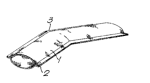
Figure 1 shows a fabric having a hollow region 1
woven therein. The hollow region is bordered by edge
regions 2 and is angled at the position marked 3.
The edge regions 2 may be trimmed as in Figure 2 and
we have surprisingly found that quite close trimming can
be made without the two layers of fabric separating even
where circumferential recoverability is provided. In
certain instances, however, it may be desirable to
provide extra strength in the edge regions 2 and this
may be done for example by increasing their size, by
the use of adhesives, or by sewing or stapling. As
mentioned above, a hollow article can be made by
incorporating a knitted stitch into the weave at the
edges of the hollow region, and this reduces the
edge region 2 to the size of a single stitch if necessary.
This will in general be the result of needle weft inser-
tion on a narrow fabric loom. The use of a continuous
weft by circular shuttle weaving of course eliminates the edge
region 2 altogether. An article having an edge region
2 may be turned inside-out to conceal the edge regions.
Figure 3 shows a hollow in the form of a Y-shaped
branch off 4 in the plane of the fabric. The warp
direction is indicated as A and the weft direction as B.
It can be seen that if a recoverable weft is provided,
the base of the Y will be recoverable only circumferentially,
whereas the oblique arms of the Y wiLl have a small
component also of longitudinal recovery. The edge regions
2 are preferably avoided, for example by a technique as
described above. The edge regions 4 of such a multi-
branched fabric can be avoided by special techniques,
for example use of two or more needles on a needle
insertion loom, or two or more shuttles on a shuttles loom.
- 29 -
A hollow branched in the thickness of the fabric
is shown in Figure 4. The branch occurs at region 5 due
to the generation at that region of four rather than two
thicknesses of fabric in the centre zone of the warp
fibres, and the generation of two rather than one
thickness of edge regions 2. The newly generated pair
of hollows will generally be blind at the branch region,
unless special techniques are used to avoid this.
Alternatively the closed ends may simply be opened by
parting the fibres after weaving. A branch-ofP made in
this way can be very flexible allowing the arms to move
apart to accomodate various configurations of substra
tes to be encapsulated. Where separation of the arms of
. . . the b.ranch-off 1s.not re.qui.red.,.it may.be sufficient a~ ..
region 5 to generate three thicknesses of fabric and
continue with a single thickness of edge regions 2.
As before, the edge regions are preferably avoided.
Figure 5 illustrates a branched hollow fabric having
hollow regions 6 running in the weft direction B. Such
hollow regions may simply be regarded as wide hollow
regions running along the warp direction but only for a
short distance. Thus, the method of construction may be
as described above. Circumferential recovery of the
regions 6 requires a recoverable warp, whereas a
dimensionally stable warp may be required where the
hollow regions extend in the warp direction in order to
avoid longitudinal recovery there. The warp feed may
simply be arranged with recoverable fibres and stable
fibres at the appropriate positions, and if the edge
region shown by the dotted line is trimmed away or
avoided substantially uniform recovery without buckling
will occur. In any of these branched fabrics it may be
desirable to increase fibre density in the branch-off
region, for example by incorporating a flat woven piece.
S~
-- 30 --
This may be desirable to increase optical coverage of
conductive fibres in screening application. Such
branchins, especially where curable fibres are incor-
porated, may be used to produce structural articles, or
couplings between other articles, for example allowing
passage of fluid. After curing the article may become
substantially rigid.
In certain more complicated designs warp recovery
may be required at a certain position across the weft,
but localized in the warp direction. This may be
achieved by changing the warp fibres during weaving
either by terminating one warp feed and substituting it
with another. Alternatively, recoverable and stable
warp fibres may both be fed and the relevant type
selectively incorporated into the weave at the correct
region. This technique, which was mentioned above,
may be analogous to the use of first and second groups
of fibres that consititute the zone of fabric where the
multiple layers are generated.
The branch-off 4 shown in Figure 6 has parallel,
arms generally with a simple seam between the branches
and is well suited for production on a narrow fabric
loom. More than two branches for example three, four or
more, up to say ten, may be provided. The branch
regions may be separated from each other laterally.
Figure 7a is a section across the warp showing
four weft insertions. The warp ends are labelled 7 and
the plcks 8. The Figure shows only seventeen ends, of
which those numbered 6-13 form a hollow region 1, and
those numbered 1-5 and 14-17 form edge regions 2. In
practise, a fabric would be made from many more ends.
The encirculed numbers 1-4 at the left-hand side
of the drawing indicate one of several possible orders
-` ~ Z~ S~
- 31 -
of weft insertions. The fifth, sixth, and subsequent
insertions would follow the first and second etc., and
be hidden behind them. The weave pattern illustrated is
a plain weave for both the edge regions 2 and both
thicknesses of the fabric at the hollow region 1. This
need not be so and other weave designs may be used,
which may be the same or different for different parts
of the fabric.
The warp ends 7 are shown in Figure 7b in position
ready for insertion of a weft insertion 8 as shown as
encircled l of Figure 7a. Ends 2,4,6,7,9,10,11,13,14 and
16 are shown lifted to produce a plain weave across the
fabric.
,:, ... .
Figure 8 is primarily a schematic program to cause
a loom to produce a hollow branch-off of the type shown
in Figure 6. Each X in the Figure tells the machine
to lift a warp end. Thus where there an X, a weft
fibre passes under a warp fibre and where there is no
X a weft fibre passes over a warp fibre. The vertical
columns 1-20 indicate twenty warp ends. The horizontal
rows 1-24 indicate twenty four weft insertions.
As in Figure 7, the number of ends illustrated is
much smaller than would generally be used in practice.
The weave generated by the program of Figure 8
is similar to that shown in Figure 7a in that it is a
plain weave over all regions. The Figure indicates that
the first weft insertion passes under warp end 1, over
end 2, under end 3 etc, since each "X" representing the warp
lifted.
The hollow region generated has been indicated by a
dotted line superimposed over the Xs that constitute the
program. For the first eight weft insertions two
- 32 -
hollow regions are produced, bordered by two edge
regons. At weft 9, the hollow branches become a single
hollow region.
; The program of Figure 8 involves four different
patterns of weft insertions in the main body and two
more in the branch which repeat, in a similar
fashion to that shown in Figure 7a. This is only one
possibility, and other weave designs could of course be
used.
Figure 9a is a weave program for a 3/3 tubular twill
showing one weave repeat, the weft cross-section of which
is shown in Figure 9b. As before, an "X" in the weave
p~ogra~ represents a warp lifted. In the weft cross-sec~ion
the numbered circles show the weft fibres, the odd
numbers forming an upper ply, and the even number
forming a lower ply. The transverse fibres are numbered
1-12, and the numbers on Figure 9a correspond to those
shown in Figure 9b.
A longer float length, such as in the 3/3
twill illustrated, results in a more flexible hollow
woven fabric. This is an advantage where the fabric
has to encapsulate irregular substrates such as for
cable harnessing, especially where movement will occur
in use.. We prefer the float to be at least 3 (a float
of 3 being illustrated in Figure 9), more preferably at
least 5.
Flexibility of this type and other weaves may be
retained by ensuring that on installation of a recoverable
fabric, some recovery for example 50-75~ of the total
available recovery remains.
A two layered tubular weave (ie. a total of four
plies) is shown in Figure 10. Figure lOa shows a weave
L5~
program and Figure lOb is a cross-section through the
weft showing one weave repeat. Such a two layered structure
may be used to combine several functions such as recovery,
environmental sealing, mechanical strength and adhesion.
These different properties may be provided in separate
layers.
For example, F`igure 1Ob could represent a hollow
article of high strength for environmental sealing in
the following way. The cross-hatched encircled numbers
(2,6,10,14,18,22,3,7,11,15,19,,23) could be an adhesive
weft, the plain encircled numbers (1,5,9,13,17,21,4,8,12,
16,20,24) could represent ~IDPE recoverable weft, the
warp fibres 1,3,4,2 could be strength fibres such as
Kevlar (trade mark), and the warp fibres 5,7,~,8 could -
be adhesive fibres. The resulting article would have
weft recovery (preferably circumferential in a tubular
structure), longitudinal strength, and an internal
adhesive layer. An article for screening could employ a
conductive fibre for example metal as warp
1,3,4,2.
Figure l l shows a composite structure formed from a
fabric having a hollow woven therein. Circumferential
recovery results from recoverable fibres 8 (preferably
weft fibres) which can be seen in cut-away region 9.
The other fibre component has coalesced to form a matrix
or continuum.
The fibres that remain in a composite structure
such as that of Figure 11 need not be provided to give
recovery, but could be for some other purpose. For
exampl.e metal or other conductive fibres may be provided
for screening or other purposes. Recoverable fibres and
other fibres may remain to produce a recoverable article
for screening. For example, circumferential recoverable
2~ ~5
- 34 -
fibres could be provided with longitudinal screerling
fibres. These two groups need not be interlaced if a
matrix were provided. The matrix could result from a
third fibrous component which originally interlaced with
the other two.
Figure 12 shows a hollow article 1 used to join
mechanically the three substrates 10, for example to
allow fluid transmission between pipes.
In Figure 13 a hollow article 1 encapsulates a
splice bundle 11 between telecommunications cables 12.
Such an article may also be used for cable harnessing,
but a large central region will not then be required due
to tne absence of a bulky cable splice. The fabric
constituting the article 1 may have zones of different
recovery ratios or strengths. For example the centre
region of the article may be non-recoverable and
the end regions recoverable.
Figure 14 shows a hollow article 1 comprising a
woven fabric having conductive fibres running
longitudinally and recovered fibres running circumferentially.
The article 1 provides electromagnetic screening over a
backshell 13 where a cable 14 is terminated. Means 15,
for example a clamp or solder, is provided for terminating
the conductive component of the article 1 to the backshell
13 and to the adjacent screen 16 of the cable 111.
... ..