Note: Descriptions are shown in the official language in which they were submitted.
-l- 63293-2610
APPARATUS AND METHOD FOR LOCATING
TO~ED SEISMIC FLOATS
The ;nventlon relates to marine seismic exploration, and
more particularlyl relates to de~ermining the position of a towed
marine seismic source.
In marine seismic exploration, impulsive sources, for
example air guns, are suspended at some preselected depth beneath
a float. The Eloat is towed by an exploration vessel ànd there
may be a plurali~y of such floats towed behind the exploration
vessel. The exploration vessel may also tow a streamer cable to
detect energy propagating upwardly from subsurface strata lying
beneath the body of water in which the vessel operates.
- The exploration vessel may determine its location in the
body of water through the use of conventional navigation systems.
Such systems determine the vessel's location but do not determine
the location of any float(s), having impulsive sources attached
thereto, that may be towed at varying positions and distances by
the vessel. Early attempts to locate floats with respect to the
vessel by employing the radar of the vessel and mounting radar
reflectors on the float have not proven to be sufEiciently
accurate nor reliable. Similarly, attempts to use acoustic
location devices have had the same or similar shortcomings.
These and other limitations and disadvantages are
overcome by the present inventionl
The invention provides an apparatus for determining the
position of a towed seismic float relative to a towlng exploration
vessel during marine seismic exploration, comprising: means Eor
determining a Eirst range to said towed seismic Eloa~ Erom a Eirst
,
,~r~
7 ~
-2- 63293-2610
preselected location on said seismic vessel, means for determining
a second range to said towed seismic float Erom a second
preselected location on said seismic vessel, and means eor
determining the point of intersection of sa:id -first and second
ranges, wherein: a microwave transponder means is disposed on said
seismic float responsive to a preselected coded signal; master
microwave transceiver means are disposed on said seismic vessel
for transmitting preselected coded si~nals functionally related to
a preselected set of first commandsi a plurality of spaced apart
microwave antennas are disposed at known locations on said seismic
vessel; antenna switching means are present for operatively
interconnecting said master microwave transceiver with one of said
plurality of antennas in functional response to a second set of
preselected commands; and controller means are present for
generating said first and second sets of preselected commands to
said master transceiver and said antenna switching means,
respectively.
The invention will now be described by way of example in
more detail with reference to the accompanying drawings, in which
Figure 1 is a plan view of a vessel towing several
floats;
Figure 2 is a plan view of a portion of the apparatus of
the present invention; and
4~
fig. 3 is a block diagram of the apparatus of the present
invention.
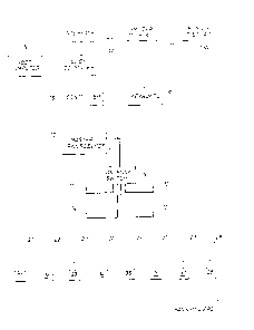
Referring now to Eig. 1, there may be seen a simplifled
plan view of a vessel 5 towing a plurality of floats 21-28. More
particularly, the vessel 5 has mounted thereon a master micro-
wave transceiver 10 which may be selectively intercoDnected with
microwave antennas 11, 12, 13 or 14. These mlcrowave antennas
11-14 are located at spaced apart and known locations relative
to the centre of the vessel 5. Although four antennas are shown
]o in fig. I (and fig. 3) 9 this number of antennas is by way of
illustration only and is not intended as any limitation on the
scope of the present invention.
The vessel 5 also has appropriate towing gear 18 and 19 for
towing floats 21-28 with cables 20. Each of the floats 21-28
have a microwa~e transponder 31-38, respectively, suitably
located on the float, also at a known position of the float.
Although eight floats are depicted in fig. 1, this number of
-float~ is for illustration only and is not intended as any
limitation on the scope of the present invention.
Referring now to fig. 3, there may be seen a block diagram
of the apparatus of the present invention. More specifically,
the master transceiver 10 is shown connected to an antenna
switch 15 for interconnecting the transceiver 10 with either
antenna 11, antenna 12, antenna 13, or antenna 14. Advantageous
embodiments of the present invention employ four such antennas.
However, more than four and fewer than four antennas are
considered within the scope of the present invention.
Continuing to refer to fig. 3, there are also depicted in
shadow or outline form the illustrative number of eight floats
3Q 21-28, as depicted in fig. 1. AgainJ the number of eight floats
is by way of illustration and not by way of limitation. Each
float 21-28 has a microwave transponder 31-38 located thereon at
a known location of the float, as described hereinbefore.
~7~
Also depicted in fig. 3 is a controller 16 that interfaces
the transceiver and antenna system with a local computer 17. The
local computer 17 has a keyboard 18 for inputting into the
compute~ 17 the desired frequency for determinlng the location
of a float and for what floats and in what sequence, if any. The
computer 17 may also have associated therewith a local display
l9a and a remote display 19b; there may be more than one of the
local and/or remote displays. The computer 17 also receives data
on the course, speed, pitch, roll, etc. of the vessel through an
external vessel status interface 40.
The local computer 17 also provides the float location,
vessel heading and time to a host computer SO in the appropriate
format for use by the host computer 50. The host computer 50 may
store this information or use it for on-vessel processing or
preprocessing of seismic data, as is known in the art.
Referring now to fig. 2, there may be seen a simplified
plan view of a portion of the apparatus of the presen~
invention, which may be e~ployed to describe t~e operation of
the present invention. Thls description is offered by way of
2~ illustration only and not by way of any limitation on the scope
of the present invention. More particularly , the antennas 11
and 13 may be seen as well as the transponder 31, which is
associated with the float 21 (not shown). Also depicted is an
x-y coordinate system centred at the centre of the vessel 5, and
distances A4 and A2 from the antennas 11 and 13 to the
transponder 31, respectively; the x axis represents the
longitudinal (fore and aft~ axis of the vessel 5.
Continuing to refer to fig. 2, the x and y coordinates of
the antennas 11 and 13 are known because of their fixed and
known location on vessel 5. What is sought is the x and y
coordinates of the transponder 31, or equivalently the position
of the float 21 (or any other preselected float) relative to the
vessel 5. This is accomplished as described hereinbelow.
-- 5 --
Referring now to fig. 2 and 3, the master transceiver 10 is
connected by the antenna switch 15 to the antenna 11, in
response to directions from the controller 16. The controller 16
also directs the master transceiver 10 to l.ocate the float 21.
In advantageous embodiments of the present invention, the master
transceiver 10 broadcasts a coded pulse sequence that selects
only the float transponder 31 as the responder over the antenna
11. All the float transponders 31-38 will receive the broadcast,
but all will disregard the broadcast except for the transponder
31. Each float transponder may have its own unique coded pulse
train to which it automatically responds.
The transponder 31 will recognize its coded pulse sequence
and as quickly as possible transmit a response. Alternatively,
each float transponder ~ay have a different transmission
frequency band althovgh this is not necessary for the present
invention when each transponder has its own unique pulse
sequence. For embodi~ents of the present invention which employ
. transponders having different transmission frequencies, it is
possible to detect the location of all the floats substantially
2Q simultaneously by employing a plurality of receiver channels
tunes to these separate frequencies in the master transceiver
1~. The controller 16 measures the time from transmission until
it first detects a transmission back from the float transponder
31. This length of tims includes the time of transmission over
and back, or twice the distance A4, as well as fixed equipment
; times, such as the reception-to-transmission turnaround time forthe transponder 31. These fixed equipment delays are subtracted
out to find the ~'flight time" and thereby the distance A4, as is
described hereinbelow. This distance A4 is also corrected for
3Q any roll and pitch of the vessel 5 during this flight tiMe.
In a similar manner, the distance A2 is determined when the
master transceiver 10 is connected to the antenna 13. The
intersection of the distances A2 and A4 determines the position
of the transponder 31, as determined by the controller 16.
~.~7~
The fixed equipment delays may be diferent for each float
transponder and should accordingly be determined for each
transponder. The controller 16 will contain these delays for
each transponder, once determined. ~hese de!lays may be deter-
mined by spacing the transponder a known calibrated distancefrom one or more antenna, or alternatively by using delay lines
havlng known delays to compare against a transponder signal
receipt.
Thus, the method of the present invention determines a
IQ plurality of ranges to a preselected location on a towed float
from a pluraliey of spaced apart antennas having known locations
on a vessel, and determines the float's location from the
intersection of these ranges from the known locations on the
vessel. This method requires a minimum of two such ranges, but
lS may employ any number than two. If more than two ranges are
employed, each pair of ranges will determine a float position;
these float positions may then be averaged or otherwise
manipulated mathematically to arrive at one position to be
employed as the location of the float. Two antennas are used in
an advantageous embodiment to determine the location of each
float, Further, as depicted in fig. 1, the antennas 11 and 13
would be employed to measure floats on the port side of the
vessel 5 ~i.e. the floats 21-24), and the antennas 12 and 14 to
measure floats on the starboard side of the vessel 5 (i.e. the
floats 25-28).
As depicted in fig. 2, the position of each float is
determined rela~ive to an x y coordinate system aligned along
the longitudinal axis of the vessel and centred at the centre of
the vessel. Alternatlvely, other coordinate systems may be used
3Q and they may have their origins at locativns other than the
centre of the vessel.
Many other variations and modifications may be made in the
apparatus and techniq~es hereinbefore described, by those having
experience in this technology, without departing from the
concept of the present invention. Accordingly, it should be
~.~ 74~ 38
clearly understoocl that the apparatus and methods depicted in
the accompanying drawings and referred to in the foregoing
description are illustrative only and are not intended as
limitations on the scope of the invention.