Note: Descriptions are shown in the official language in which they were submitted.
~l%~7~
Docket H-20~9-c
IMPROVEMENT IN LIQUID-GAS
ABSORPTION PROCESS
This application is a continuation-in-part of
co-pending application Serial No. 06/835,842, filed
March 3, 1986.
FIELD OF THE INVENTION
This invention relates to an improvement in
liquid-gas contact apparatus and process where sulfur dioxide
is absorbed into or reacted with the liquid. A particular
application is in the absorber of the Wellman-Lord process for
the removal of sulfur dioxide from exhaust gases by aqueous
; 10 sulfite solution, particularly from combustion power plant flue
gases, althou~h it is also applicable to exhaust streams from
smelters, sulfuric acid plants, or any other sulfur dloxide
containing gas streams.
BACKGRO~ND OF THE INVENTION
,
As an e~ample of a process requiring an aqueou.s
liquid-gas contact apparatus, the Wellman-Lord process of
sulfur dioxide removal from stack gases employs an aqueous
alkali sulfite solution (usually sodium sulfite) which
chemically combines with the sulfur dioxide gas in an
20 absorption tower by forming sodium bisulfi-te. The process
includes a separate regeneration facility to convert the
bisulfite back to sulfite and recover sulfur dioxide gas which
is compressed and bottled or converted sulfuric acid or to
elemental sulfur. In the case of flue gases from coal fired
25 plants, a separate unit for removal of fly ash and chlorides
is included.
Because of large capital costs and high energy
requirements to overcome the pressure drop in the absorber,
in the regenerable Wellman-Lord process~ non-regenerable flue
30 gas desulfurization processes have been the more popular
choice in the past, in spite of the major problem of disposal
- of solid waste produced by such processes.
. .,
:~`
, - -, : , :: '. ' , ,
- . ~ - ; ~ . ~ . .
. - . ~ : . ' '' ' .
.
: - .. : .~
~7~37~
The present invention is an improvement in
absorption apparatus and its operation and in particular the
process of the invention relates to the absorber of the
Wellman-Lord process whereby capital costs and parasitic power
5 requirements are reduced so as to make the regenerable process
more economic and thus avoid the solid waste problem of the
non-regenerable processes.
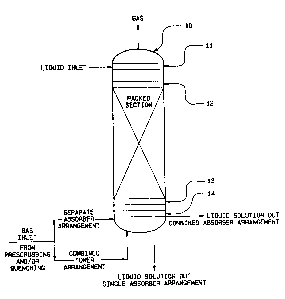
DESCRIPTION OF T~IE DRAWINGS
Figure 1 is a schematic of an adsorption column 10,
10 indicating the position of a liquid distributor 11, an
optional packing retainer 12, packing support 13, and
conventional gas distributor and liquid collection, if
necessary, 1~, with the liquid and gas inlets and outlets
indicated.
Figure 2 is an exploded broken view of a portion of
a preferred li.quid distributor having a supply trough 20, a
spacing element 21, and a flow guide 22. Attached to flow
guide 22 are drip fingers or rods 23 having ends adjacent
packing (shown schematically) at 24.
Figure 3 is a schematic rib view, assembled, of
the parts of a preferred distributor shown in Figure 2.
Figure 4 is an exploded schematic side vi.ew of a
similar arrangement to Figure 2, but with the element 21
replaced by spacers 25.
Figure 5 is an enlarged cross-sectional view of a
portion of element 21.
DESCRIPTION OF THE I~VENTION
By employing liquid distribution at extremely low
li~uid flow rates and high efficiency random dumped packi.ng,
30 the present invention can achieve the absorption step in a
single relatively short packed column of low pressure drop,
and without the requirement of recycle of the absorbate
solution prior to regeneration.
The flow rate Eor liquid fed to the top of the tower
35 is from 0.05 to 1.0 gallons per minute per square foot, or
more preferably from 0.2 to 0.3 gallons per minute per square
. ~
. .
..
- ~ :
,. -:
~ 3t~
foot~ Only fresh absorbant solution i B employed, without
recycle. With the use of such low liquid flow rates, the
tower packing is chosen ~o that itB operation i8
oompatible with the low li~uid rate. One ~uitable type
is that in which the operation i~ primarily one of
combination and separation of droplets, rather than by a
spreading of the liquid on large wetted areas of the
packing. A suitable packing of this type is a high void
volume packing shown in U.S. Patent 4,511,519 to Hsia.
The paaking has a large number of drip point6, a
relatively low surface area, but r~latively long total
length of non-aligned interacting edges.
Beaause of the low li~uid xate of the pre6ent
invention, wi~h one half to one tenth of the liquid
retention time of the convention practice using trayed
towers or a plurality of packed towers with trap trays,
in the Wellman-~ord process, the problem of oxidation of
sulfite to sulfate is reduced by an amount of 50% to as
muàh as 90%. This is important in that the sulfate
reduces the absorption efficiency of the liquid and thus
must be removed in the regeneration proce6s, adding
capital and operational expenses to the process. In
addition, the sulfate slats are a solid waste which must
be disposed of in an environmentally safe manner.
In order to distrlbute liquid onto the packing
so as to take advantage of the low flow rate a drip type
distributor which provides at least 3 and preferably at
least 6 to 9 feed points uniformly spaced per square foot
may be employed. A suitable liguid distributor
originally intended for non-polar liguids which can be
adapted for this purpose is shown in U.~. Patent
4,264,538 to Moore. ~hile this typQ of distributor as
disclosed in the patent was designed for organie liquid6,
it can bs adapted for use in the present invention by
use of hydrophylic coatings, as later desoribed below.
Other types of liquid distributors may be employed,
~ .
: . - - '
.. .
.
.
and, in the larger diameter towers a spray type distributor,
sultably designed for low liquid rates may be preferable,
because it is less costly. Any other type oE distributor
suitable to deliver the re~uired low liquicl flow may be
5 employed. If the distributor is less efficient, the length
of the packed bed must be increased. Thus less efficient
distribution methods may be employed, with a penalty paid in
the higher costs and pressure drop inherent in the deeper bed.
When a metal ~stainless steel) trou~h t~pe or drip
10 type distributor is used, the surfaces of the distributor,
outside of the feed troughs which convey the liquid, should be
coated with a hydrophylic microporous coating which causes a
film of liquid to be formed on such surfaces as the liquid
flows on them by gravity. The drip -fingers, which are coated,
15 should also all extend to be close to or contacting a surface
of the packing (or packing retainer, if used). The distance
should not be substantially greater than the diameter of the
liquid droplets being fed, so as to avoid entrainment of the
liquid by the countercurrent flowing gas. Such an arrangement
20 produces maximum efficiency and can avoid the need for a
demister at the exit of the absorber.
In the following examples a packing element as shown
; in Figures 7 through 10 of U.S. Patent 4,511,519 was employed,
having a diameter of 3-1/2 inches and an axial height of 1-1/4
25 inches. The packing depth was 7.5 feet. A liquid distributor
such as described in U.S. Patent 3,937,769 was employed,
having 9 drip fingers per square foot. The operative surfaces
of the distributor were coated with a resin latex drag
resistant hydrophylic coating as described in U.S. Patent
30 4,467,070, sold by Hydromer, Inc., Whitehouse, N.~. The
distributor also included a dimpled, perforated plate as shown
at 21 in Figures 2, 3, and 5. The dimples were alternately
facing in opposite directions~ The dimples 50 of E`ig. 5 in
this case were 3/16 inches apart, in an ~ mil steel sheet, to
35 help distribute the liquid. The tower was 30 inches in
diameter. The li~uid composition was composed as follows:
' ~`
' ,' ' " ' - - ' ' ' , ' , , "
.
~L~7~37~
Weight %
Na2S3 17.4
Na2S2O5 2.9
Na2S4 6.0
H2O 73.7
The test results are sho~n in Table ~.
Table II shows the pressure drop and the calculated
mass transfer coefficient Eor each runO The highest mass
transfer coefficients were obtained for the runs in which the
10 gas rate was such that the tower was operating in the loading
zone. That is, the gas rate was sufficiently high to cause
increased liquid hold-up in the tower res~llting in increased
pressure drop and gas liquid contacting because of the aclded
space taken up by the liquid.
Table I
Liquid GasGas SO2 Parts/Million
Run Rate Rate
No. GPM/Ft2 Lbs/hr/ft2 Inlet Outlet
1 0.145 1813.3717.2 160
2 0.142 3374.6711.7 220
3 ~.157 3526.09~4.5 510
4 0.312 3631.71402.1 400
0.157 1964.11065.7 600
6 0.324 3~81.4676.0 80
Table II
Run Pressure ~rop Mass Transfer C~efficient IcGa
No. Inches of H2O/ft LB Moles/hr-ft -ATM
1 0.105 13.4
2 0.388 22.1
3 0.429 15.5
4 0.429 28.2
0.113 6.8
6 0.461 39.4
The use of a single packed bed greatly reduces the
35 capital cost ~f the absorber compared to present design
practice used in ~ellman-Lord plants. The single packed bed
also greatly reduces the operating cost, primarily in the area
of the blower horsepower needed to feed the gas through the
absorber but also by eliminating the presently required liquid
'' -`' - ~ "` ',:
. : . , ~
.- , . ~ ' :, ` ' -
recycle pumps. The packed be~, to achieve these ener~y
savings, preferably uses a high efficiency packin~ which can
achieve in a minimum length of bed -the necesqary mass transfer
contacting efficiency, and has sufficiently low pressure drop
5 to make the energy savings possible.
Partial capital cost and energy saving benefits can
be achieved by using less than optimum arrangements o~ this
process inventicn. That is, rather than replacing all of the
pump-a-round sections in prior absorption processes with a
10 single packed bed, it is possible to combine some of the
pump-a-round sections into two or three sections. These
sections can still employ li~uid recycle to achieve the high
liquid rate operation but still have some pressure drop
reduction. The energy savings here comes from the elimination
15 of some of the trap trays. The elimination of the trap tra~s
also saves considerable capital; the trap trays are very
expensive because OL their stainless steel construction~
One further partial simplified configuration is
possible. This configuration uses two beds. The top section
20 would be a packed section using the once through regenerated
absorption solution at low liquid rate. Thus, making an off
gas with the lowest possible SO2 content because of low
S2 vapor pressure in the regenerated solution. The lower
bed would be recirculated for the benefit of the higher liguid
25 rates for easier liquid distribution, and would tend to
eliminate potential salt precipitation problems caused by dry
areas.
Thus the single bed, with no pump around, employing
low liquid rate may be used to absorb SO2 from a gas stream
30 directly from its source, or, as the final stage, from any
intermediate pollution control apparatus including fly ash
removal and chloride removal where required for coal burning
power plants.
In normal operation typically a 10 to 20~
35 stoichiometric e~cess of sorhent sulfite solution will be fed
to the tower, based on the concentration of the sulfite and the
- ~ :
~ '7~;37~i
liquid and gas feed rates. In some cases, however, it may be
more desireable to fully react the sorbent liquid for efficient
regeneration, than to remove all oE the S02 from the gas.
In such cases the liquid feed would be somewhat deEicient,
5 on a stoichiometric basis.
;
- : . : . - . .- - . . :
- - : : . . :- , . . ' . ' ; , :
: : -