Language selection

Search

Patent 1274408 Summary

Third-party information liability

Some of the information on this Web page has been provided by external sources. The Government of Canada is not responsible for the accuracy, reliability or currency of the information supplied by external sources. Users wishing to rely upon this information should consult directly with the source of the information. Content provided by external sources is not subject to official languages, privacy and accessibility requirements.

Claims and Abstract availability

Any discrepancies in the text and image of the Claims and Abstract are due to differing posting times. Text of the Claims and Abstract are posted:

  • At the time the application is open to public inspection;
  • At the time of issue of the patent (grant).
(12) Patent: (11) CA 1274408
(21) Application Number: 1274408
(54) English Title: DENTAL FORCEPS
(54) French Title: DAVIER
Status: Expired and beyond the Period of Reversal
Bibliographic Data
(51) International Patent Classification (IPC):
  • B25B 7/00 (2006.01)
  • A61C 3/16 (2006.01)
  • B25B 7/02 (2006.01)
  • B25B 7/04 (2006.01)
(72) Inventors :
  • PINDER, EDWARD DENIS (Canada)
(73) Owners :
  • EDWARD DENIS PINDER
(71) Applicants :
  • EDWARD DENIS PINDER (Canada)
(74) Agent:
(74) Associate agent:
(45) Issued: 1990-09-25
(22) Filed Date: 1987-06-15
Availability of licence: N/A
Dedicated to the Public: N/A
(25) Language of filing: English

Patent Cooperation Treaty (PCT): No

(30) Application Priority Data: None

Abstracts

English Abstract


ABSTRACT OF THE DISCLOSURE
The usual forceps used in a dental laboratory are
the straight or rectilinear devices commonly employed by the
medical profession. A better forceps design for use in dental
laboratories includes a straight body defined by a pair of arms
which are interconnected in a reverse scissors fashion ei.,
the jaws open when the handles of the forceps are pressed
towards each other, with loops defining handles at one end,
bent tips at the other end extending outwardly from the remainder
of the arms at approximately 45° to the plane of such arms,
and small jaws, each with a serrated edge, pivotally mounted
on the free ends of the tips for engaging the interior of a
crown to hold the latter. The jaws can pivot around axes
perpendicular to the axes of the tips, or around the
longitudinal axes of such tips. Rather than squeezing
inner and outer surfaces of a crown, the novel forceps
grip opposing surfaces of the interior of a crown.


Claims

Note: Claims are shown in the official language in which they were submitted.

THE EMBODIMENTS OF AN INVENTION IN WHICH AN EXCLUSIVE
PROPERTY OR PRIVILEGE IS CLAIMED ARE DEFINED AS FOLLOWS:
1. Dental forceps comprising a pair of elongated arm
means; hinge means pivotally interconnecting said arm means in
reverse scissors fashion; handle means on one end of each said arm
means for operating the forceps; and jaw means pivotal on the other
end of each said arm means for facilitating gripping of the sloping
surfaces of a dental crown.
2. Dental forceps according to claim 1, wherein said
other end of each said arm means bends out of the plane of the
remainder of said arm means, whereby, when said arm means occupy
a horizontal plane, said jaw means are inclined upwardly with
respect to such plane.
3. Dental forceps according to claim 2, wherein each
said jaw means is adapted to rotate around an axis perpendicular
to the longitudinal axis of said other end of said arm means.
4. Dental forceps according to claim 2, wherein
each said jaw means is adapted to rotate around the longitudinal
axis of said other end of said arm means.
5. Dental forceps according to claim 2, including
ratchet means releasably interconnecting said pair of arm means
proximate said handle means.
6. Dental forceps according to claim 5, wherein
said ratchet means includes elongated, arcuate first lug means
extending inwardly from one said arm means beneath the other said

arm means; short, second lug means extending inwardly from the
other said arm means into overlapping relationship with said
first lug means; and opposing teeth means on said first and second
lug means for releasably interconnecting said one end of said
pair or arm means.

Description

Note: Descriptions are shown in the official language in which they were submitted.


~ 3~
This invention relates to dental forceps, and in
particular to forceps intended for use in a dental laboratorv.
In genera', conventional dental forceps are the
same as those used by the medical profession. Such forceps
include a body defined by a pair of arms, which are interconnected
scissors fashion. Loops on one end of each arm define handles
for manipulating the forceps. The arms are releasably inter-
connected at such one end by a short ratchet. The other ends of
the arms define jaws, which taper to a point, and include
opposed serrated inner edges for grippinq one edge of a dental
crown in the same manner as tweezers or needle nose pliers.
Because only a small surface area of each jaw actually contacts
the crown, the likelihood of slipping or dropping of the crown is
somewhat high. Moreover, an area of the outer surface of the
crown is covered by the tip of one of the jaws preventing or
interferring with work in such area.
The object of the present invention is to overcome
the above-identified problems by providing relatively simple
dental forceps, which are capable of gripping a large area of
the interior of a dental crown for holding such crown.
Accordingly, the present invention relates to dental
forceps comprising a pair of elongated arm means; hinge means
pivotally interconnecting said arm means in reverse scissors
fashion; handle means on one end of each said arm means for operating
the forceps; and jaw means pivotal on the other end of each said arm
means for
~r ,~

4~
facilitating gripping of the sloping surface of a dental crown.
In this case, "reverse scissors fashion" is intended to
mean that the jaw means are forced apart when the handle means are
pressed towards each other.
The invention will be described in greater detail with
reference to the accompanying drawing which illustrates the prior
art and a preferred embodiment of the invention, and wherein:
Figure l is a plan view of a pair of conventional forceps;
Figure 2 is a perspective view of a dental crown held
by the jaw end of the forceps of Fig. l;
Figure 3 is a perspective view from above and one end
of dental forceps in accordance with the present invention; and
Figure 4 and 5 are partly sectioned, perspective views
of two different types of jaws on the forceps of Fig. 3 in the
use positions.
With reference to Figs. 1 and 2, conventional forceps of
the type used in dental laboratory include a pair of arms 1 and 2,
which are pivotally interconnected scissors fashion near jaws 3 on
one end thereof. A loop defining a handle ~ is provided on one
end of each of the arms 1 and 2. A pair of opposing lugs 6 and
7 extend inwardly from the arms 1 and 2 for defining a short rachet.
One lug 6 has a hook (not shown) on the free end thereof for engaging
teeth 8 on the opposing lug 7. Thus, the lugs 6 and 7, and
consequently the jaws 3 can be releasably locked together.
As shown in Fig. 2, one disadvantage of the forceps

4~
decribed above is experienced when holding acrown 10. The
crown 10 has one open end 11 with sloping or tapering sides
around such open end, when the jaws 3 of the forceps are used
to grip one side of the crown 10, they usually grip only one small
edge portion of the crown 10. Thus, there is the distinct
possibility of slipping or dropping of the crown.
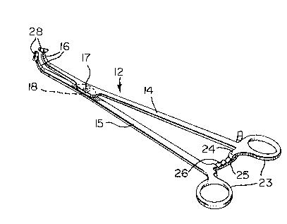
Referring -to Fig. 3, the forceps of the present invention
which are generally indicated at 12 include a pair of arms 14. The
arms 14 and 15 are pivotally interconnected near their jaw ends 16
in reverse scissors fashion by a pin 17 with an enlarged head 18 for
seating the forceps firmly on a bench or table (not shown) while
working on a crown 20 or 21 (Figs. 4 and 5, respectively). Loops 23
on one end of each of the arms 14 and 15 define handles for
manipulating the forceps 12.
A short lug 24 with a downwardly extending tooth at its
free end extends inwardly from one arm 14. An elongated arcuate
lug 25 with teeth 26 on the upper surface thereof extends inwardly
from the other arm 15 beneath the lug 24 and the arm 14. Thus,
the lugs 24 and 25 define a ratchet for releasably locking the arms
14 and 15 in various open or closed positions.
The other jaw ends 16 of the arms 14 and lS bend upwardly
at an angle of approximately 45 with respect to the plane of the
remainder of the arms, so that a crown 20 or 21 will be positioned
above the table or bench. A short jaw 28 is pivotally mounted on
the free end of each of the arms 14 and 15.

The jaws 28 are mounted for rotation around lnclined
axes such that the serrated outer edqes 30 of the jaws can engage
the inner surface 31 of a crown 20 (Fig. 4). With this arrangement,
the jaws conform to the inclined surface of the crown 20, and can
be spread apart a distance sufficient to firmly retain the crown
2Q on the forceps. Thus, it is seen that the forceps act in a
direction which is the reverse of the direction of operation of
the conventional forceps, i.e. the jaws 28 are forced apart
rather than together in order to hold a crown.
Referring to Fig. 5, -the second embodiment of the
forceps is intended for use in a larger crown 21, e.g. a molar.
The forceps include all of the elements of the forceps of Fig.
4, except that the jaws 28 are replaced with jaws 33. The jaws
33 are pivotally mounted on the ends of the arms 14 and 15 for
rotation around axes which are extensions of the longi-tudinal
axes of the ends of the arms 14 and 15.
The use of forceps having jaws which extend into a
crown for holding the latter faciiitates work on the entire
outer surface of the crown without releasing and re-grasping
the crown at another location. Because the surfaces of crowns
are inclined or sloped the use ofrotatablejaws on the ends of
the arms of the forceps improves the gripping or hol~ing action
of the forceps.
-- 4

Representative Drawing
A single figure which represents the drawing illustrating the invention.
Administrative Status

2024-08-01:As part of the Next Generation Patents (NGP) transition, the Canadian Patents Database (CPD) now contains a more detailed Event History, which replicates the Event Log of our new back-office solution.

Please note that "Inactive:" events refers to events no longer in use in our new back-office solution.

For a clearer understanding of the status of the application/patent presented on this page, the site Disclaimer , as well as the definitions for Patent , Event History , Maintenance Fee  and Payment History  should be consulted.

Event History

Description Date
Inactive: IPC from MCD 2006-03-11
Inactive: CPC assigned 2001-05-18
Inactive: CPC removed 2001-05-18
Time Limit for Reversal Expired 1997-09-25
Letter Sent 1996-09-25
Grant by Issuance 1990-09-25

Abandonment History

There is no abandonment history.

Owners on Record

Note: Records showing the ownership history in alphabetical order.

Current Owners on Record
EDWARD DENIS PINDER
Past Owners on Record
None
Past Owners that do not appear in the "Owners on Record" listing will appear in other documentation within the application.
Documents

To view selected files, please enter reCAPTCHA code :


To view images, click a link in the Document Description column. To download the documents, select one or more checkboxes in the first column and then click the "Download Selected in PDF format (Zip Archive)" or the "Download Selected as Single PDF" button.

List of published and non-published patent-specific documents on the CPD .

If you have any difficulty accessing content, you can call the Client Service Centre at 1-866-997-1936 or send them an e-mail at CIPO Client Service Centre.


Document
Description 
Date
(yyyy-mm-dd) 
Number of pages   Size of Image (KB) 
Abstract 1993-10-12 1 21
Cover Page 1993-10-12 1 9
Drawings 1993-10-12 1 24
Claims 1993-10-12 2 39
Descriptions 1993-10-12 4 126
Representative drawing 2001-05-03 1 9
Notice: Maintenance Fee Reminder 1997-06-26 1 119
Fees 1996-09-04 3 154
Fees 1996-08-29 1 16
Fees 1996-08-12 3 150
Fees 1994-09-14 1 33
Fees 1995-08-24 1 41
Fees 1993-09-14 1 25
Fees 1992-08-24 1 31