Note: Descriptions are shown in the official language in which they were submitted.
~27~L9~
~IELD OF INVENTION
The present invention relates to air freshener di6pensers of the
type containing in a reservoir a liquid fragrance composition that is
carried to an emanator pad by wick means for 6ubsequent diffusion from
the pad to the atmosphere. More specifically, the present invention
relates to an ~ir freshener di6penser having a rotatable cover member
overlaying an emanator pad holding means, 6aid cover means being
rotatable with respect to the pad holding means to open and close at
least one fragrance-diffusion aperture in said cover means. Most
specifically, the air freshener dispenser of the present invention
includes means to retain the emanator pad holding means within the
cover means, and means to detachably 6ecure the emanator pad holding
means to the reservoir.
BACXGROUND OF T~E INVENTION
Fragrance diffusers including wick means to convey a volatile
fragrance composition from a rese Noir to the atmosphere directly or
to an emanator pad for subsequent diffusion to the atmosphere are
known. Thus, U.S. 1,332,659 to Bates illustrates an evaporimeter
compri~ing a reservoir, a cylindrical, hollow shaft extending upwardly
of the reservoir, and a perforated disk normal to the shaft, there
being a wick within the 6haft, the strands of the wick being spread
across the d$sk, and a cover placeable over the disk. U.S. 4,477,414
~7~491
to Muramoto et ~1. discloses a wickless evaporative container, the
liquid in the reser~oir being drawn up through a feed pipe rather than
a wick. In the vaporizing device of Dupuy, U.S. 2,383,960, the
reservoir has a wide-mouth orifice in which is inserted pad holding
means, the pad thus held being in contact with a wick extending into
the reservoir. A cover is superposed over the pad holding insert,
apertures in the cover cooperating with apertures in the pad
holdinginsert to provide ad~ustability of the air diffusion passages
defined by the assembly.
U.S. 1,377,909 to Moulin discloses a container, a wick extending
upwardly from the container through a holed-stopper, absorbent
material in contact with the top of the wick, and an apertured cover
affixed to an upstanding skirt of the container.
SUMMARY OF THE INVENTION
It is an object of the present invention to provide an adjustable
air freshener dispenser of the wick type.
It is a further object of the present invention that the air
freshener dispenser include emanator or absorbent pad holding means
retained within the cover member for ~aid unit.
-3-
It i6 anot~er ob~ect o the present lnvention that the emanator
pad holding means be attachable to the neck of the container.
Yet another object of the present invention is to provide
adjustability of the diffusion rate of fragrance composition wicked
to the emanator pad by rotational movement of the cover member
relative to the location of the emanator pad holding means when same
are connected to the neck o~ the container in operational position.
These and other ob~ects and advantages of the present invention
are described in greater detail below, with reference to the accom-
panying drawings. A summary of the invent~on follows.
The invention in one aspect provides an air
freshener dispenser comprising a container having
an openins; ~ w$ck depending into the container; an emanator
p~d; emanator pad holding ~ean6 detachably connected to the
container and retn$ning the emanator pad in contact with the
wick, 6aid pad holding mean6 including at least one fragrance
diffu~ion channel and ~t least one upwardly extending eide wall
member; a cover member having a top and a substantially cylindri-
cal ~ide wall snd lncluding at lea6t one fragrance diffu6ion
aperture registrable with ~aid fragrance diffu6ion channel, and
retention means comprieing a first mating eurface a6sociated
with the pad holding ~Qans and a ~econd mating curface a6soci-
-4-
~7~491
ated with the cover ~e~ber, said ~ting ~urfaces in operativeposition detachnbly r~talning the cover member on the pad
holding means detachably connected to the container, the first
~ating surface being inoperative in cooperation with ~aid cover
member ~ubstantially cylindrical ~ide wall to detachably retain
said cover ~ember on the pad holding ~eans, eaid cover member
being rotatable in ~aid detachably retained position with
respect to~6aid pad holding mean6, the pad holding ~eans-being
nonrotatable with re~pect to the con~ainer by the torquing force
for rotating the cover member on the pad holding means, whereby
rotation of the cover member enables ~aid at least one fragrance
d~ffusion aperture and ~aid at lea6t one fragrance diffusion
channel to be brought into regi~try.
The invention in a further aspect provides an air
freshener dispenser comprising a container having
an opening; a wick depending into the container; an emanator
pad; emanator pad holding means detachably connected to the
container and retaining the emanator pad in contact with the
wick, 6aid pad holding mean~ including a planar base portion
having a central aperture through which said wick extends, at
least one ~lde wall member `including a plurality of fragrance
diffu6ion channels, said planar base portion having a plurality
of radial epokelike portions between the central aperture and
the p~rlphery of th~ bace portion defin~ng air circulation
aperturQs therein; a cover ~e~ber having a top and a
cub~tantially cylindric~l ~lde wall and including a plurality of
fragrance dl~fu~ion apertur~ equal in number to the fragrance
diffu~ion chann~l~ and registrable with said ~ragrance diffusion
f
A s
~274491
channel~, and r~tQntiGn ~neanE~ oper~tive to ~etachably retain the
cover member on the p~d holding ~eans, 6aid cover member being
rotat~ble in said detachably retained po~ition with respect to
said said holding ~an6, the pad holding means being
nonrotatable with respect to the container by the torquing force
for rstating the cover member on the pad holding means, whereby
rotation of the cover ~ember enables 6aid Pt least one fragrance
diffusion aperture ~nd said at least one ~ragrance diffusion
channel to be brought into regi6try.
RIEF DESCRIPTION OF ~HE D~WINÇS
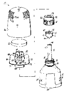
Fig. 1 is an exploded perspective view of the air freshener
dispenser of the present ~nvention.
Fig. 2 is a partially broken away front view of the cover member
of the air freshener dispenser shown in Fig. 1.
Fig. 3 is a cross-sectional view of the emanator pad holder across
lines 3-3 of Fig. 4.
Fig. 4 ~s a top plan view of the emanator pad holder, a portion of
which is broken away.
Fig. 5 i6 a vertical half-section cross-sectional view of the air
freshener dispenser in its operational mode, the emanator pad omitted
for clarity.
Fig. 6 is a partial vertical half-section cross-sectional view of
the air freshener dispenser in its nonuse mode, the cover, emanator
pad, and emanator pad holder having been o~i~ted for clarity.
A -5a- ¦
PESCRIPTION OF THE PREFERRED EMBODIMENT
Referring to Fig. 1, an exploded perspective view of the dispenser
10 of the present invention, the air fre5hener dispenser 10 comprises
a container 12 for containing a volatile liquid fragrance
composition,a neck insert member 14, a wick 16, a closure cap 18, an
emanator pad holder 20, an emanator or absorbent pad 22, and a cover
member 24.
The container 12 has a body 31 and a neck 32, the container 12
being a reservoir for the volatile air fragrance composition. The
neck 32 includes threads 33, and below the threads a peripheral flange
34 6hown herein as an octagonal flange. One or more land surfaces 37
are also included, the lands 37 frictionally engaging the cover member
24. The container can be fabricated by injection blow molding using a
suitable plastic material, for example, polyethylene, polypropylene,
and polyethylene terephthlate. A suitable capacity of the container
is about 3-4 fluid ounces. The fragrance composition typically com-
prises a fragrance, an emul~ifier, a volatile solvent, for example,
isopropyl alcohol, optionally a colorant, and deionized water.
As illustrated in Fig. 1, and more specifically in the assembly
Fig. 5, the insert member 14 is adapted for friction fit within the
bore of the neck 32 of the container 12. The insert member 14 com-
127~ 9~
prises an annular top portion 42 from which depends an outer annular6kirt 41, 6aid ~kirt 41 frictionally engaging the interior 6ide wall
of the neck 32. The top 42 of the insert member 14 includes an an-
nular peripheral flange 43 that ~eats on the top edge of the neck 32.
A vent hole 45 is also provided in the top 42. Also downwardly
depending of the annular top portion 42 i5 a circular hollow shaft 44
that receives the wick 16. The wick 16 extends through the
cylindrical shaft 44, the bottom end of which typically abuts the base
36 of the container. The wick 16 extends above the top 42 of the
insert member 14 a predetermined distance. The wick preferably
comprises an interior core 46 of an absorbent wicking material and an
outer sheath 47 of a plastic material that prevents the strands of the
absorbent material 46 from unravelling. Suitable materials include
natural and synthetic fibers that are capable of being formed into a
wick, for example, Scribrod~ manufactured by Baumgartner Papers S.A.
The outer sheath 47 can be any wet-strength polymer capable of
retaining the inner fibers, and may be permeable or nonpermeable. In
the preferred embodiment, the absorbent fibers are polyester, and the
outer sheath is a polyester film. The neck insert may be made, for
example, of low-density polyethylene.
The closure cap 18 illustrated ln nonuee assembly with the device
in Fig. 6, as well as in Fig. 1, comprises a cylindrical body 51, the
interior side wall of which is provided with threads 55 suitable for
mating assembly with the threads 33 on the container neck 32. The
closure cap 18 further includes an exterior upwardly extending skirt
-7-
~;27449~
52 formlng with the cap body 51 an outer shoulder 54. ~nterior of theskirt 52 and extending upwardly of the cap body 51 ~8 ~ dome member
53, the dome member being of 6uitable height to receive that portion
of the scrib rod 16 extending above the top 42 of the neck insert 14.
As illustrated in Fig. 6, during nonuse the cap 18 is secured to
the neck of the container 32 by means of the complementary threads 33
and 55 on the neck 32 and on the interior surface of the cap body 51,
respectively. That portion of the wick 16 extending above the top 42
of the insert member 14 i6 received in the dome member 53. Suitable
headspace is provided in dome member 53 so that the top of the wick
does not come in contact with the top of the dome member 53. When
sealed by the cap 18, the volatile fragrance composition cannot
diffuse or otherwise escape from the container 12. A circular sealing
boss 56 is dependingly interiorly provided on the top of the cap body
51 to provide a positive seal when the cap 18 is tightened about the
neck 32 of the container 12.
The emanator pad holder 20 is next described with reference to
Figs. 1, 3, 4, and 5. The pad holder 20 comprises a base portion
designated generally by numeral 61. The base portion 61 comprises a
raised annular central portion 63 defining a large central aperture 80
and a plurality of spokelike portions 62 extending radially outwardly
from the central portion 63 to the periphery of the emanator pad
holder, the radial ~pokelike portions defining therebetween air
1274~9~
circulation apertures 81. The pad holder 20 further compri6es ~ peri-
pheral skirt portion 71 that depend6 downwardly from the outermost
periphery of the 6pokellke portions 62, the 6kirt portion 71 including
proximate it5 bottom an exterior peripheral boss 72, the purpose of
which i6 hereinafter described~ Extending upwardly from the 6kirt
portion 71 is a plurality of 6ide wall 6egments 64, said side wall
segments 64 being in radial align~ent with and extending partially
over the apertures 81, and forming therebetween a plurality of chan-
nels 82, said channel6 82 being in radial alignment with the spokelike
portions 62 of the base poxtion 61. Annular support portions 76 are
provided between the central portion 63 and the interior edge 75 of
the air circulation apertures 81.
The uppermost portion 65 of the side wall 6egments 64 is arcuately
disposed towards the interior of the pad holder 20 and terminates in
annular arcuate edges 66. The 6ide walls 77 of the wall 6egments 64
including the arcuate portion 65 are tapered so that the bottom of the
6ide wall 6egment 64 i6 60mewhat circumferentially wider than the
arcuate edge 66.
Depending from the central portion 63 is a hollow cylindrical
shaft 68, which includes an interiorly provided circular protrusion
70, whose purpose is hereinafter described. ~etween the 6haft 68 and
the 6kirt 71 are a plurality of radial ribs 78 depending from the
6pokelike portions 62 of the base portion 61. The 6ide wall 6egments
~7449~
64 ~160 include ribs 69 pro~ecting inwardly therefrom. The rib 69
provides additional strength to the 6ide wall segment6 64 and prevents
same from warping or incurring other deformation. The ribs 69 further-
more secure pad 22 within the pad holder. The central portion 63 of
the base portion 61 further includes an interior annul~r lip 73 that
slopes downwardly towards the large aperture 80, said lip 73 including
a plurality of slots 84, whose purpose is hereinafter described.
The emanator pad 22 i6 a coarse material, e.g., a diecut felt
material, provided preferably as two pads one above the other. The
emanator pad may be inserted into the pad holder 20 by outwardly
bending one of the side wall segments 64, which have sufficient
flexibility and resiliency to allow such insertion. The pad holder
may be made for example from polypropylene or high density
polyethylene by conventional molding ~ethods. The emanator pad may be
made from woven or nonwoven materials capable of transporting liquids
by capillary action, and preferably is a mixture of cotton, 6ynthetic,
and wood pulp fibers, plus a wet-strength binder.
Referring to Figs. 1 and 2, the cover member 24 compri6es a
slightly f~ustoconical body 91 including a top 92, there being a
plurality of 6paced apart air circulation apertures 93 through the
--10--
.
~4~
body 91. Each of the ~perture6 93 may compri6e a plurall$y of
vertical 610t6 93~. Referring to Fig. 2, a partiAlly ~roken-away
front view of the cover member 24, an interior
circular flange 95 depends from the top 92 of the cover member 24, and
an exterior circular flange 96 al60 depends fxom the top 92 of the
cover member 24, 6aid exterior flange further including at least one
stop member 97.
Referring to Fig. 5, the pad holder 20 (including the pads 22, not
shown) is detachably retained within the cover member as follows: the
emanator pad holder 20 is adapted for coinc~dent placement proximate
the top of the cover member 24. Thus, side wall segments 64 are
essentially arcuately radially identical with the body 91 of the cover
member. By urging the pad holdPr 20 towards the top 92, the arcuate
edges ~6 of the wall segments 64 engage the ~nterior flange 95, as
most easily understood by review of Fig. 5. The flexible and
resilient ~ide wall 6egments 64 flex outwardly 61ightly to achieve
thi6 mating. Similarly, peripheral boss 72 on the skirt ~1 engages
complementary boss 98 on the interior of the body 91 of the cover
~ember 24. The emanator pad holder 20 is thereby rotatably engaged
within the cover member 24. The circular flange 96 provides a
rotation 6urface for the arcuate portion 65 of the side wall 6egment
64, with the 6top member 97 being adapted to restrict rotation of the
emanator pad holder 20 when the apertures 93 are in registry with the
channels 82 or when the fiide wall Eegment6 64 fully close the
apertures 93. The emanator pad holder 20 (including the emanator pads
22) is secured within the cover member 24 during manufacture, and is
intended to remain integrally n6sembled during 6hipment and use.
As indicated ~bove, during shipment (or during nonuse) the closure
cap 18 is connected to the neck 32 of the container 12. ~uring this
shipping or nonuse mode, the lower edge of the ~haft 68 rests loosely
on ~houlder 54 of the closure cap in 18, the upstanding skirt 52 being
received into the 6haft 68, with the circular pro~ection 70 providing
additional frictional engagement.
To use the device, the consumer 6imply removes the CQVer
member-emanator pad holder assembly, then removes the closure cap 18,
and finally replaces said assembly. The shaft 68 receives the neck 32
of the container 12, and the complementary matin~ surfaces 34 and 70
are engaged. Furthermore, the circular lip 73 of the central base
portion 63 flexes upvardly slightly, and compressively engages the top
42 of the insert member 14. The lip 73 is not especially resilient,
but flexes in view of the flex slots 84 provided therein. The wick
16, in view of the connection between the container 12 and the pad
holder 20, is in abutment with the emanator pad 22, and the fragrance
composition may be wicked from the container 12 to the emanator pad
22.
The consumer may ad~ustably regulate the rate of diffusion of the
,~27~
fragrance materi~l from the emanator pad to the atmosphere ~y
rot~tionally opening or closing the cover mem~er 2~ to vary the size
of the air circulation pa6sages defined by the epertures 93 and the
channel~ 82. Diffu~ion ~6 enhanced by the prcvision of the updraft
grooves 35 and the apertures 81, which provide a path for air flow t~
the vapor space above the emanator pad holder 2~. Air contact with
the bottom of the entire emanator pad is established by having the
e~anator pad rest on the raised central portion 63 of the base portion
61, thereby establishing an annular channel normal to the vertical
axis of the device 10. The tor~uing force necessary to rotate the
cover member 24 about the emanator pad 20-container 12 assembly is
less than that re~uired to rotate the emanator pad 20 about the
emanator pad-container assembly. However, the emanator pad
holder-cover assembly may rotate as one unit when the stop means 97
abut a ~ide wall 6egment 64. This may be prevented by including a
6top member on the interior 6urface of tbe shaft 68 that cooperates
with flange 34, thereby limiting rotation.
It is to be understood that the air freshener device of the
subject invention as well as its component parts may have or include
parts or equivalents not specifically recited herein without departing
from the spirit and scope of the claims appended below.