Language selection

Search

Patent 1274798 Summary

Third-party information liability

Some of the information on this Web page has been provided by external sources. The Government of Canada is not responsible for the accuracy, reliability or currency of the information supplied by external sources. Users wishing to rely upon this information should consult directly with the source of the information. Content provided by external sources is not subject to official languages, privacy and accessibility requirements.

Claims and Abstract availability

Any discrepancies in the text and image of the Claims and Abstract are due to differing posting times. Text of the Claims and Abstract are posted:

  • At the time the application is open to public inspection;
  • At the time of issue of the patent (grant).
(12) Patent: (11) CA 1274798
(21) Application Number: 1274798
(54) English Title: DEVICE FOR MOUNTING A DRAWBAR ON A REVOLVING CABLE OF A SKI LIFT AND DRAWBAR ASSEMBLY FOR A SKI LIFT
(54) French Title: DISPOSITIF POUR FIXER UNE BARRE DE TRACTION AU CABLE TOURNANT D'UN MONTE-PENTE, ET LADITE BARRE DE TRACTION
Status: Expired and beyond the Period of Reversal
Bibliographic Data
(51) International Patent Classification (IPC):
  • B61B 12/12 (2006.01)
  • B61B 11/00 (2006.01)
(72) Inventors :
  • BRUCKSCHLOGL, MAX (Austria)
(73) Owners :
  • MAX BRUCKSCHLOGL
(71) Applicants :
  • MAX BRUCKSCHLOGL (Austria)
(74) Agent: SMART & BIGGAR LP
(74) Associate agent:
(45) Issued: 1990-10-02
(22) Filed Date: 1987-03-25
Availability of licence: N/A
Dedicated to the Public: N/A
(25) Language of filing: English

Patent Cooperation Treaty (PCT): No

(30) Application Priority Data:
Application No. Country/Territory Date
A 1122/86 (Austria) 1986-04-25

Abstracts

English Abstract


ABSTRACT
DEVICE FOR MOUNTING A DRAWBAR ON A REVOLVING CABLE OF A SKI
LIFT AND DRAWBAR ASSEMBLY FOR A SKI LIFT
A device for mounting a drawbar (3) on a revolving
cable (1) of a ski lift comprises a holder (2), to which the
drawbar (3) is connected and which is mounted on the
cable (1) for rotation about the axis of said cable.
to permit a simple adjustment of the drawbar in height (3)
to the user of the lift, the holder (2) carries an arm (4),
which protrudes from the cable (1) and has a free end, on
which the drawbar (3) is mounted for rotation about an axis
which is parallel to the cable (1). Said arm is rotatable by
means of a handle (8).


Claims

Note: Claims are shown in the official language in which they were submitted.

CLAIMS
1. In a device for mounting a drawbar on a revolving
cable of a ski lift, comprising
a holder 9 which defines a first axis and is
adapted to be mounted on said cable for rotation about
said first axis in a position in which said first axis
coincides with the axis of said cable, and
mounting means, which are carried by said
holder and adapted to be connected to said drawbar,
the improvement residing in that
said mounting means comprise an arm, which
protrudes from said holder and has an outer end remote
from said holder, and pivot means for pivotally connecting
said drawbar to said arm at said outer end about a second
axis, which is approximately parallel to said first axis
and
a handle is carried by said mounting means and
adapted to be operatively connected to said drawbar and
operable to pivotally move said drawbar about said second
axis.
2. The improvement set forth in claim 1, wherein
said pivot means comprise a bearing bushing
mounted on said arm at said outer end and centered on
said second axis, and a shaft, which extends through
and is rotatably mounted in said bearing bushing and
has a first end provided with means for non-rotatably
connecting said shaft to said drawbar and a second end
which is non-rotatably connected to said handle.
- 6 -

3. The improvement set forth in claim 2, wherein
said handle has a longitudinal axis and
said shaft is provided with means for non-
rotatably connecting said drawbar to said shaft in a
position in which said drawbar extends at an angle to
said longitudinal axis of said handle with respect to
said second axis.
4. The improvement set forth in claim 1, wherein
said handle has a longitudinal axis and
said pivot means comprise means for non-rotatably
connecting said drawbar to said handle in a position in
which said drawbar extends at an angle to said longitudinal
axis of said handle with respect to said second axis.
5. In a drawbar assembly adapted to be mounted on a
revolving cable of a ski lift, comprising
a drawbar,
a holder, which defines a first axis and is
adapted to be mounted on said cable for rotation about
said first axis in a position in which said first axis
coincides with the axis of said cable, and
mounting means, which are carried by said
holder and connected to said drawbar,
the improvement residing in that
said mounting means comprise an arm, which
protrudes from said holder and has an outer end remote
- 7 -

from said holder, and pivot means, which pivotally connect
said drawbar to said arm at said outer end about a second
axis which is substantially parallel to said first axis,
and
a handle is carried by said mounting means and
operatively connected to said drawbar and operable to
pivotally move said drawbar about said second axis-
6. The improvement set forth in claim 5, wherein
said pivot means comprise a bearing bushing
mounted on said arm at said outer end and centered on
said second axis and a shaft, which extends through and
is rotatably mounted in said bearing bushing and has a
first end that is non-rotatably connected to said drawbar
and a second end that is non-rotatably connected to said
handle.
7. The improvement set forth in claim 6, wherein
said handle has a longitudinal axis and
said drawbar extends at an angle to said lon-
gitudinal axis with respect to said second axis.
8. The improvement set forth in claim 7, wherein
said drawbar extends at an angle from 60 to 90 degrees
to said longitudinal axis with respect to said second
axis.
9. The improvement set forth in claim 5, wherein
said handle has a longitudinal axis and
- 8 -

said drawbar extends at an angle to said longitu-
dinal axis with respect to said second axis.
10. The improvement set forth in claim 9, wherein said
drawbar extends at an angle from 60 to 90 degrees to said
longitudinal axis with respect to said second axis.
11. The improvement set forth in claim 5, wherein
said pivot means pivotally connect said drawbar
to said arm for a pivotal movement between a position of
rest, in which said drawbar extends inwardly from said
pivotal mounting means toward said holder, to a position
of use, in which said drawbar extends outwardly from said
pivot means, and
spring means are provided, which urge said drawbar
toward said position of rest.
- 9 -

Description

Note: Descriptions are shown in the official language in which they were submitted.


~EVICE FOR ~OUN~ING ~ DRAWBAR ON A REVO~IMG CABLE OF ~ SEI
LIF~ ~ND DRA~YBAR A$SE~BLY FOR A SKI ~IF~
BACEGROUND 0~ ~HE INVEN~ION
Thi~ invention relates to a device ~or mounti~g a
drawbar on a revolving cable of a ski li~t ~ which device
compri~e~ a holder~ which is connected to the drawbar and
i~ mounted for rotation about the axis of the cable.
~ drawbar, ~hich i~ rigidly ~ecured to the haulage
cable of a ski li~t 7 will exert a torsional ~ome~t on the
cable. It i9 de~ired to avoid ~uch a torsional mome~t, on
the one hand, and to ensure that all drawbars ~ill assume
the ~ame po~ition relative to the pulleys around which the
cable i~ rever~ed, on the other hand. From ~u~trian Patent
Speci~ication 320,020 it i~ known that thi~ can be accom
pli~hed in that the holder~ connected to the drawbars are
mounted on the cable for rotation about its axis. That
rotatable mounting of the drawbars on the cable by mean~
of the holders al~o permi~ a certain ad~ptation of the
drawbar, which laterally protrude~ ~rom the cable~ to the
height of the user o~ the ski lift. But that adaptation i~
usually insufficient 80 that the cable i~ lifted by hand in
order to change the drawbar in height. ~hi~ require~ the
u~er o~ the ~kl lift to exert a substantial ~orce and to
take up part o~ the weight of the cable and of the load
on the cable.
~, "

~2
~h~
It i~ an obaect o~ the invention to avoid the
di~advantages outlined hereinbefore and to provi~e an
improved devi~a for ~ecurlng a drawbar to a revolving
cable o~ a ski li~t, whioh de~ice permit~ the u~er o~
the ski lift to move the drawbar i~ a ~imple manner to
the position which i8 most convenient for the user in
~uch a man~er that the course of the cable need not be
altered.
~ his object is accompli~hed in accordance with
the invention in that the holder carrie~ an arm9 which
protrudes from the cable, the drawbar i~ mounted on ~aid
arm a-t that end therso~ which i8 remote from the cable
and for rotation about an axi which i~ ~ub~tanti~lly
parallel to the cable~ ~nd the drawbar i9 rotatable b~
means of a handle~
A~ the drawbar i8 not rigidly connected to
the holder but i~ conneoted to it for rotation about
an ~xis which i8 sub~tantially parallel to the cable,
the drawbar can be adju~ted in height par~llel to itself
without a ~hifting of the cable in height becau~e the
elevation o~ the drawbar will be determined by the angular
position of the protruding arm carried by the holder. For
this reason the user o~ the ski li~t can u~e the handle to
adjust the drawbar to the optimum position ~or dragging that
u~er of the ski lift and the drawbar ser~es only to transmit
to the user of the ski lift tho~e traction forces which act
in the direction of tra~el rather th~n also forces which are
transverse to said direction.
A particularly simple desig~ will be obtained
~ithin the ~cope o~ the in~ention if the drawbar i~ ~ecured
to one and of a shaft~ which extend~ through and i~

f!'L~7~
rotatably mounted in a bearing bushing that i~ mounted on
ths arm carried by the holder~ and the handla i~ ~ec~ed
to the other end of the ~haft. I~ tha device i~ properly
de3igned that ~ha~t will extend approxim~tel~ on the level
o~ the lower arm of a u~er o~ the ~ki lift when the draw~ar
is in dragging positio~. In -that case the drawbar aan be
pi~o-tally moved by the handle mainly by a rotation o~ the
underarm about it~ longitudinal axi8. In order to permit
the u~er to hold hi~ or her hand in a natural po~ition ~or
actua~ing the handle, the h~ndle may exte~d at an angle to
the drawbar with respect to the axis of rotation of the
drawbar. Such an arrangement will en~ure an optimum actio~
of the force that i~ exerted to adju~t the dra~bar. OwiDg
to the anatomical relation~hip~, a ~e~irable ~ngle between
the handle and the drawbar i8 in the range ~rom ~0 and 90.
If the drawbar can be rotated against the force of
a return ~pring from a position of re~t, to which it has
been swung in toward the holder, to a position i~ which
the dra~bar extend~ outwardly from the arm, the release
o~ the drawbar by the user after use will cause the drawbar
to perform an inward pivotal mo~ement to its position of
rest, in which the drawbar extend~ toward the holder. In
that position the holder will depend from the cabl0 under
the action of gravit~ becau~e the holder i8 mounted to be
freely rotatable about the axi~ of the cable~ When the
drawbar extend~ outwardly *rom the arm~ the drawbar will
be ~paced a relatively large distance from the cable.
Nevertheles~ when the drawbar has been~swung in~ the
length of the device will not exceed the le~gth of the
arm.
Brief De~cri tion of the Drawin~
~ igure 1 is a top plan view showing a drawbar
assembly comprising a device for mounting a drawbar on

~ revolving cable of the ski lif~t with that Qs~embly in
po~ition of u~e.
Figure 2 is a front elevation ~howin~ that
a9 ~embly and
Figure 3 i8 a side elevation showing the assembly
in po~ition of rest.
~ ~
An embodiment of the in~ention ~ill ~ow be
explained more in detail with reference to the drawing.
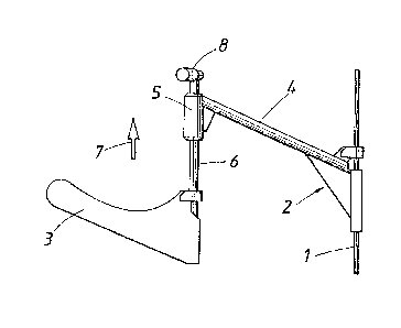
~ he illustrated device comprises a holder 2,
~hich is mounted on a revolving ¢able 1 of a ~ki lift
for rotation about a fir~t axis, ~hich coincides ~ith
the axis of the cable. ~he holder 2 carries a drawbar 3.
~ dif~erence from the k~own devices of that kind resides
in that the drawbar 3 is not no~-rotatably connected to
the holder 2 but is rotatably mounted on the outer end
of an arm 4D which i~ carried by the holder 2 and protrudes
from the cable 1. On that outer end of the arm 4 the
drawbar 3 is mounted for rotation about a ~econd axis,
~hich i8 approximately parallel to the first axi~ he
arm 4 i~ pro~ided at its outer end with a bearing bushing 5.
A shaft 6 extends through the bearing bushing 5 and is
rotatably mounted tharein. ~t that end of the ~haft 5
which is the trailing end in the direction of travel,
indicated by an arrow 79 the drawbar 3 is non-rotatably
connected to the ~haft 6. A handle 8 for rotating the
drawbar 3 is secured to the leading end of the shaft 5.
As is particularly apparent from Figure 2 the handle 8
extends at an angle to the drawbar 3 with respect to the
axis of rotation of the drawbar. ~hat angle may desirably

~7~
be in the range from 60 to 90 degree~ and in the illustrated
embodiment amount~ to about 75 degrees. Thi~ will permi t the
u~er to hold hi~ or her hand in ~ natural position -to rotate
the drawbar 3 to it~ position o~ use~
~ spring~ not 3hown, urges the dra~bar 3 toward a
po~ition of re~t, which is shown in Figurz 3 and in which
ths dra~bar 3 extends i~wardly toward the holder 2 and the
holder depend3 ~rom the cable 1 under gravity. Adjacent to
the l~wer pulley for re~ersing ths cable 1 o~ the ski li~t~
a suitable guide i~ provided for pivotally rai~ing the arm 4
to an approximately horizont~l po~ition and the drawbar 3 i~
~imultaneously rotated to a depe~ding posi-tion in which the
handle 8 extend~ toward the waiting u~er o~ the ~ki lifto
This is indicated in phantom in ~igure 2. The u~er o~ ths
ski li~t then ~ake~ the handle 8 a~d actuate~ the same to
turn the drawbar 3 to it~ po~itio~ of u~e in which the
drawbar 3 protrudes approximately horizontally ~rom the
arm 4 ( ee ~igure~ 1 and 2), Becau~e during the rotation
o~ the handle 8 the sha~t 6 i~ approximately parallel to
the u~derarm of the user of the ski lift, the force exerted
by the user of the ski lift will act in a de~irable manner
50 that the actuation of the device i9 simple. The handle 8
can also be used to adju~t the drawbar 3 ln height without
a need to shift the cable 1 because the drawbar 3 i9 pivoted
to the arm 4 and the arm 4 is pivoted to the ca~le 1.

Representative Drawing
A single figure which represents the drawing illustrating the invention.
Administrative Status

2024-08-01:As part of the Next Generation Patents (NGP) transition, the Canadian Patents Database (CPD) now contains a more detailed Event History, which replicates the Event Log of our new back-office solution.

Please note that "Inactive:" events refers to events no longer in use in our new back-office solution.

For a clearer understanding of the status of the application/patent presented on this page, the site Disclaimer , as well as the definitions for Patent , Event History , Maintenance Fee  and Payment History  should be consulted.

Event History

Description Date
Inactive: IPC from MCD 2006-03-11
Inactive: Inventor deleted 1999-08-30
Inactive: Adhoc Request Documented 1994-10-02
Time Limit for Reversal Expired 1994-04-03
Letter Sent 1993-10-04
Grant by Issuance 1990-10-02

Abandonment History

There is no abandonment history.

Owners on Record

Note: Records showing the ownership history in alphabetical order.

Current Owners on Record
MAX BRUCKSCHLOGL
Past Owners on Record
None
Past Owners that do not appear in the "Owners on Record" listing will appear in other documentation within the application.
Documents

To view selected files, please enter reCAPTCHA code :


To view images, click a link in the Document Description column. To download the documents, select one or more checkboxes in the first column and then click the "Download Selected in PDF format (Zip Archive)" or the "Download Selected as Single PDF" button.

List of published and non-published patent-specific documents on the CPD .

If you have any difficulty accessing content, you can call the Client Service Centre at 1-866-997-1936 or send them an e-mail at CIPO Client Service Centre.


Document
Description 
Date
(yyyy-mm-dd) 
Number of pages   Size of Image (KB) 
Abstract 1993-10-13 1 18
Claims 1993-10-13 4 120
Cover Page 1993-10-13 1 14
Drawings 1993-10-13 2 27
Descriptions 1993-10-13 5 211
Representative drawing 2001-10-25 1 7
Fees 1992-09-11 1 29