Language selection

Search

Patent 1274864 Summary

Third-party information liability

Some of the information on this Web page has been provided by external sources. The Government of Canada is not responsible for the accuracy, reliability or currency of the information supplied by external sources. Users wishing to rely upon this information should consult directly with the source of the information. Content provided by external sources is not subject to official languages, privacy and accessibility requirements.

Claims and Abstract availability

Any discrepancies in the text and image of the Claims and Abstract are due to differing posting times. Text of the Claims and Abstract are posted:

  • At the time the application is open to public inspection;
  • At the time of issue of the patent (grant).
(12) Patent: (11) CA 1274864
(21) Application Number: 1274864
(54) English Title: SEAL
(54) French Title: JOINT D'ETANCHEITE
Status: Term Expired - Post Grant
Bibliographic Data
(51) International Patent Classification (IPC):
  • F16J 15/22 (2006.01)
  • F16J 15/16 (2006.01)
(72) Inventors :
  • BECK, GERALD H. (United States of America)
(73) Owners :
  • MACROTECH POLISEAL, INC.
(71) Applicants :
  • MACROTECH POLISEAL, INC. (United States of America)
(74) Agent: MACRAE & CO.
(74) Associate agent:
(45) Issued: 1990-10-02
(22) Filed Date: 1986-10-15
Availability of licence: N/A
Dedicated to the Public: N/A
(25) Language of filing: English

Patent Cooperation Treaty (PCT): No

(30) Application Priority Data:
Application No. Country/Territory Date
842,182 (United States of America) 1986-03-21

Abstracts

English Abstract


ABSTRACT
A composite seal comprising a primary seal
element and a secondary sealing element. The primary
seal element is more readily deformable than the secon-
dary seal element. Juxtaposed surfaces of the seal
elements are configured to minimize extrusion of the
primary seal element past the secondary seal element.


Claims

Note: Claims are shown in the official language in which they were submitted.

I CLAIM:
1. A composite seal for disposition about a
circular element having a central axis, said seal
comprising
an annular primary sealing element having a
durometer of 60 to 90 on the Shore A Scale,
an annular secondary sealing element having a
durometer of 95 to 125 on the Shore A Scale,
said secondary element being of a generally
U-shaped radial cross section defined by
radially spaced axially extending legs con-
nected by a radially extending bight portion,
the legs of said secondary seal element being
normally engageable with said circular ele-
ment and with the wall of a supporting ele-
ment, respectively,
the legs on said secondary element having
conical axial end faces, respectively,
inclined axially and radially toward the
bight portion thereof,
said primary element having a pair of
radially spaced lips with axially and
radially inclined surfaces complementary to
and in juxtaposed relation to the end faces
on said secondary element to preclude extru-
sion of said primary element past the legs of
said secondary element.

2. A seal in accordance with claim 1 wherein
the lips on said primary seal element are axially
inclined toward the bight portion of said secondary
seal element whereby the interface between the inclined
surfaces on said primary seal element and the conical
end faces on said secondary seal element is less than
the radial dimension of the conical end faces.

Description

Note: Descriptions are shown in the official language in which they were submitted.


~7~
SEAI~
EACKGROUND OF THE INVENTION
Hydraullc cylinder~ of the type disclosed in
U. S. Letters ~atent No. 3,848,880 generally utilize a
seal aszembly on the piston thereof to prevent leakage
of fluid past the piston. As taught in saLd patent, a
unitary composite seal assembly for such cylinders
comprises a relatively hard synthetic rubber U-cup and
a relatively softer synthetic rubber sealing ring that
fills a central recess in the U-cup. The sealing ring
may be mechanically retained or bonded within the U-
cup .
SUMMARY OF THE INVENTION
The present invention provides an improvedcomposite seal assembly suitable for sealing high
pressure systems ln low temperature conditions.
The compo ite seal comprises an annular pri-
mary sealin~ element and an annular secondary sealing
element, The primary sealing element is made of a
relatively deformable material and is mechanically
retained in a complimentary undercut in the secondary
element.
The secondary sealing element is made of a
relatively rigid material such as hard thermoplastic
and has opposed conical surfaces that function as anti-
extrusion supports for the primary sealing element. In
addition, the secondary sealing element contains secon-
dary sealing lips whlch act as redundant seals upon

installation and which are energized further -th-rough
displacement of the primary sealing element.
An advantage over similar seal arranyements is
offered in that pressure is not required to energize the
secondary sealing element as an active seal resulting in
superior initial sealing and film breaking action in low
pressure applications where high fluid viscosity and low
temperatures are encountered. The secondary seal is further
energiæed as pressure increases thereby to act as a redundant
seal to the primary sealing element throughout the entire
pressure range of the system. The configuration of the
interface between the primary and secondary seal elements
precludes extrusion of the relatively soft primary element
between the secondary element and the cylinder wall.
In summary, therefore, the present invention may be
considered as providing a composite seal for disposi-tion
about a circular element having a central axis, the seal
comprising an annular primary sealing element having a
durometer of 60 to 90 on the Shore A Scale, an annular
secondary sealing element having a durometer of 95 to 125 on
the Shore A Scale, the secondary element being of a generally
U-shaped radial cross section defined by radially spaced
axially extending legs connected by a radially extending
bight portion, the legs of the secondary seal element being
normally engageable with the circular element and with the
wall of a supporting element, respectively, the legs on
the secondary element having conical axial end Eaces,
respectively, inclined axially and radially toward the bight
~ 2-

~4
portion thereof, the primary element having a pair of
radially spaced lips with axially and radially inclined
surfaces complementary to and in juxtaposed relation to the
end faces on the secondary element to preclude extrusion
of the primary element past the legs of the secondary element.
BRIEF DESCRIPTION OF THE DRAWINGS
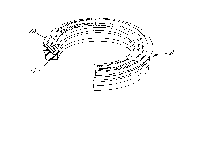
Figure 1 is a perspective view, partly in cross
section, of the composite seal of the present invention;
Figure 2 is a cross-sectional view of the composite
seal in its free or uninstalled condition; and
Figure 3 is a cross-sectional view of the composite
seal in the installed condition between a piston and cylinder.
-2A-

6~
DETAIL~:D DESCRIPTION OF I~E PREE'ERRED
EMBODIMBNT OF THE INVENTION
In accordance with a preferred embodiment of
the instant invention, a composite seal 8 comprises a
primary sealing element 10 that is engagad with a U-
shaped secondary sealing element 12. The primary ele~
ment 10 is made of relatively soft and deformable
elastic material such as synthetlc rubber or other
synthetic elastomers~ either thermoset or thermo-
plastic. The primary element 10 preferably has a duro-
meter of between 60 and 90 on the Shore A Scale.
The secondary sealing element 12 is of
generally U-shaped cross section and is made from a
relatively rigid yet deformable or yieldable material,
including flexible or relatively rigid elastomers,
relatively hard rubber; or thermoset or thermoplastic
plastics, such as polyurethane and polyamids having a
durometer of between 95 and 125 on the Shore A ,Scale.
In all case~ the material of the element 12 is harder
and less readily deformable than the material of the
primary element 10.
As best seen in Figs. 2 and 3, the secondary
element 12 has an annular T-shaped recess 14 therein
for the acceptance of a dependlng generally T-shaped
annulus 16 on the primary element 10 to mechanically
lock the elements 10 and 12 together.
In accordance with one eature of the instant
invention, the secondary element 12 has a pair of oppo-
sitely directed legs 18 and 20 that are engaged at all
times with a wall 22 of a cylinder 23 and wall 24 of a

piston 26, respectively. Simllarly/ the primary ele-
ment 10 has a pair of annular lips ~8 and 30 that are
engageable with the wall 22 of the cylinder 23 and wall
24 of pis~.on 26, respectively. The e7ement 10 has a
groove 32 between the lips 28 and 30 to augment lateral
deflection thereof when the seal 8 is subjected to
pressurized fluid.
In accordance with another feature of the
instant invention, the element 10 is provided with con-
vergant inclined surfaces 34 and 36 extending axially
and radially from the lips 28 and 30, respectively, to
preclude extrusion of the lips 28 and 30 past the legs
18 and 20 of the element 12. ~his anti-extrusion
feature is complemented by the inclined end faces 38
and 40 on the legs 18 and 20 of the element 12 which
support complementary inclined sur~aces 42 and 44,
respectively, on the element 10 thereby to further
preclude extrusion of the element 10 past the lips 18
and 20 on the element 12.
In the installed condition shown in Fig. 3,
the central recess 32 between the lips 28 and 30 of the
element 10 is deformed from the initial condition shown
in Fig. 2 to facilitate deflectlon of the lips 28 and
30 thereby to maintain a bias on the cylinder wall 22
and piston wall 24 even though there is no signiflcant
fluid pressure within cylinder 22. Stated in another
manner, the lips 18 and 20 of the element 12 and the
lips 28 and 30 of the element 10 are all de~ormed upon
installation so as to maintain initial sealing contact
with surface 22 of the cylinder 23 and surface 24 of

the piston 26,
While the preferred embodiment of the inven-
tion has been disclosed, it should be appreciated that
the invention is susceptible of modlfication without
departing from the scope oE the following claims.

Representative Drawing
A single figure which represents the drawing illustrating the invention.
Administrative Status

2024-08-01:As part of the Next Generation Patents (NGP) transition, the Canadian Patents Database (CPD) now contains a more detailed Event History, which replicates the Event Log of our new back-office solution.

Please note that "Inactive:" events refers to events no longer in use in our new back-office solution.

For a clearer understanding of the status of the application/patent presented on this page, the site Disclaimer , as well as the definitions for Patent , Event History , Maintenance Fee  and Payment History  should be consulted.

Event History

Description Date
Inactive: Expired (old Act Patent) latest possible expiry date 2007-10-02
Inactive: IPC from MCD 2006-03-11
Inactive: Late MF processed 2005-10-19
Letter Sent 2005-10-03
Inactive: Late MF processed 2004-10-21
Letter Sent 2004-10-04
Inactive: Late MF processed 2003-10-21
Inactive: Late MF processed 2001-12-12
Letter Sent 2001-10-02
Grant by Issuance 1990-10-02

Abandonment History

There is no abandonment history.

Fee History

Fee Type Anniversary Year Due Date Paid Date
MF (category 1, 7th anniv.) - standard 1997-10-02 1997-09-11
MF (category 1, 8th anniv.) - standard 1998-10-02 1998-10-01
MF (category 1, 9th anniv.) - standard 1999-10-04 1999-09-29
MF (category 1, 10th anniv.) - standard 2000-10-02 2000-09-19
MF (category 1, 11th anniv.) - standard 2001-10-02 2001-12-12
Reversal of deemed expiry 2005-10-03 2001-12-12
MF (category 1, 12th anniv.) - standard 2002-10-02 2002-09-19
Reversal of deemed expiry 2005-10-03 2003-10-21
MF (category 1, 13th anniv.) - standard 2003-10-02 2003-10-21
MF (category 1, 14th anniv.) - standard 2004-10-04 2004-10-21
Reversal of deemed expiry 2005-10-03 2004-10-21
Reversal of deemed expiry 2005-10-03 2005-10-19
MF (category 1, 15th anniv.) - standard 2005-10-03 2005-10-19
MF (category 1, 16th anniv.) - standard 2006-10-02 2006-09-18
Owners on Record

Note: Records showing the ownership history in alphabetical order.

Current Owners on Record
MACROTECH POLISEAL, INC.
Past Owners on Record
GERALD H. BECK
Past Owners that do not appear in the "Owners on Record" listing will appear in other documentation within the application.
Documents

To view selected files, please enter reCAPTCHA code :


To view images, click a link in the Document Description column. To download the documents, select one or more checkboxes in the first column and then click the "Download Selected in PDF format (Zip Archive)" or the "Download Selected as Single PDF" button.

List of published and non-published patent-specific documents on the CPD .

If you have any difficulty accessing content, you can call the Client Service Centre at 1-866-997-1936 or send them an e-mail at CIPO Client Service Centre.


Document
Description 
Date
(yyyy-mm-dd) 
Number of pages   Size of Image (KB) 
Abstract 1993-10-12 1 10
Claims 1993-10-12 2 35
Drawings 1993-10-12 1 52
Descriptions 1993-10-12 6 162
Representative drawing 2001-07-08 1 11
Maintenance Fee Notice 2001-10-29 1 178
Late Payment Acknowledgement 2002-01-06 1 172
Late Payment Acknowledgement 2003-11-04 1 166
Maintenance Fee Notice 2004-11-21 1 173
Late Payment Acknowledgement 2004-11-21 1 166
Maintenance Fee Notice 2005-10-24 1 173
Late Payment Acknowledgement 2005-10-24 1 166
Fees 1996-09-24 1 40
Fees 1995-09-25 1 46
Fees 1994-09-25 1 39
Fees 1993-10-03 1 18
Fees 1992-09-22 1 30