Note: Descriptions are shown in the official language in which they were submitted.
CONTP~OL SYSTEM FOR QUICK HEATER
l~ACKGROUND OF THE INVENTIOM
The present invention relates to a control system
for a quick heater for quickly heating the in~erior of the
passenger compartment of a motor vehicle which is driven by
an internal combustion engine. More particularly, the
present invention relates to a quick heater control system
for monitoring the operating conditions of various
operating components of a quick h ater and detecting a
~ailure of any of the operating components to stop the
operation of the quick heater and/or issue an alarm.
There have been proposed various conventional
heaters for heating the passenger compartments of motor
vehicles. According to one heater design, cooling water is
extracted from the internal combustion engine through a
hot-water pipe and passed through a heater body comprising
a heater core and a blower, air is supplied to and heated
by the heater body, and the heated air is delivered into
the passenger compartment to heat the interior thereof.
Another prior motor vehicle heater includes a burner for
burning fuel independently of the internal combustion
engine, the heat generated by the burned fuel being
utilized to heat the interior of the compartment.
The heater which utilizes the engine cooling
water is not suitable for quickly heating the interior of
the compartment since it takes a long time to increase the
temperature of the cooling water. One prob:Lem with a
heater employing fuel independently of the internal
combustion engine and using a burned gas itself for
heating the interior of a compartment is that the hot
air produced by the burner for heating -the compartment
interior cannot be controlled as desired. Althouyh -the
burner heater is capable of quickly heating the
compartment interior, of controlling the heating hot-air
sufficiently, and of hea-ting the compartment interior
according to a desired hea-ting posltion, i-t fails to
sufficiently detect and indicate failures of various
components of the heater.
SUMMARY OF THE INVENTION
It is a feature of one embodiment of the present
invention to provide a control system for a quick heater
for quickly heating the interior of the passenger
compartment of a motor vehicle, the control system being
capable of detec-ting failures of various components of
the heater to stop the operation of the heater.
Another feature of one embodiment of the present
invention is to provide a control system for a quick
heater for quickly heating the interior of the passenger
compartment of a motor vehicle, -the control system being
capable of detecting failures of various components of
the heater to issue failure alarms.
Still another feature of one embodiment of the
present invention is -to provide a control system for a
quick heater for quickly heating the interior of the
passenger compartment of a
motor vehicle, the control system being capable of
detecting failures of various components of the heater
to stop the operation of the heater and issue failure
alarms.
According to an embodiment of the present
invention there is provided a control system for a
quick heater including a burner having an atomizing
device for atomizing fuel and an igniting device for
igniting the fuel atomized by the atomizing device,
and a heat exchanger for heating air with the heat of
combustion gases produced by burning the atomized fuel
in the burner, the control system~comprising an
atomizing glow plug heatable by supplied electric
energy for promoting the atomization of fuel effected
by the atomizing device; detecting means for detecting
the electric resistance of the atomizing glow plug and
producing a detected signal indicative of the detected
electric resistance; determining means for determining
whether the atomizing glow plug fails or not based on
~0 the detected signal from the detecting means; and
means for shutting off the heater based on a signal
from the determining means which indicates a failure
of the atomizing glow plug.
~5 In accordance with another embodiment of the
present invention there is provided a control system
for a quick heater including a burner having an
atomizing device for atomizing fuel and an igniting
device for igniting the fuel atomized by the atomizing
device, and a heat exchanger for heating air with the
heat of combustion gases produced by burning the
atomized fuel in the burner, the control system
comprising: an igniting glow plug heatable by
supplied electric energy for igniting fuel atomized by
the atomizing device; detecting means for detecting
the electric resistance of the atomizing glow plug and
producing a detected signal indicative of the detected
- 3 -
~7~ 3~
.
electric resistance; determininy means for determininy
whether the atomiziny ylow plug ~ails or not based on
the detected siynal from the detecting means; and
means for shutting off the heater based on a siynal
from the determininy means which indicates a failure
o~ the atomizing glow plug.
The above and other features and advankages of
the prQsent invention will become more apparent from
the following description when taken in conjunction
with the accompanying drawings in which a preferred
embodiment of the present invention is shown by way of
illustrative example.
BRIEF DESCRIPTION OF' THE DRAWINGS
Fiy. 1 is a block diagram of a control system for
a quick heater accordiny to an embodiment of the
present invention;
Figs. 2A and 2B are a flowchart of an operation
sequence of the control system.
- 3a -
, . .~
~7~
DESCRIPTION OF THE PREFERRED EMBODIMF,NT
An embodiment of the present invention will
hereinafter be describea in detail with reference to the
drawings.
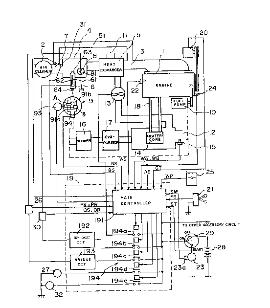
An engine 1 which may be a diesel engine or a
gasoline engine is associated with a quick h~ating burner 4
for burning fuel to heat the interior of a passenger
compartment, the quich heating burner 4 being disposed in a
intake pipe 3 serving as an air duct extending from an air
cleaner 2. A heat exchanger 5 is connected to the intake
pipe 3 downstream of ~he quick heating burner 4 in the
direction of air flow through the intake pipe 3. A bypass
passage 51 is connected to the intake pipe 3 for supplying
air to the engine 1 to burn fuel therein.
The quick heating burner 4 has therein an
atomizer 6 for heating fuel to atomize the same/ a bypass
valve 7 for controlling an air inlet port for supplying air
to be mixed with atomized fuel into a combustible mixture,
and an ignition glow plug 8 for igniting and burning the
combustible mixture. The atomizer 6 has a pipe-shaped or
rod-shaped atomizer glow pIug 61 of a ceramic material for
heating the fuel to atomize the same. The glow plug 61
includes a central resistor wire 62 having a positive
temperature coefficient for heating the glow plug 61 upon
energization. The ignition glow plug 8 is also in the form
of a pipe or rod made of a ceramic material such as silicon
nitride (Si2No4) and includes a central resistor wire 81
for heating the ignition glow plug 8 upon energization.
In one end of the atomizer ~, there is defined an
ejector hole 63 for ejecting fuel as it is heated and
atomized by the atomizer glow plug ~1 into the quick
heating burner 4. The other end of the atomizer 6 has a
fuel inlet hole 64 communcating with a fuel supply unit 9
having a fuel valve. The bypass valve 7 which serves as
means for controlling the air inlet port to suppl~ air to
be mixed with atomized fuel is controlled by a command from
a main controller 191 tdescribed later). When the bypass
valve 7 i5 fully opened, air to be mixed is not introduced
and bypasses the quick heating burner 4. When the bypass
valve 7 is opened to a degree "1", it introduces a
predetermined small amount of air. When ~he bypass valve 7
is opened to a degree "2", it introduces a predetermined
medium amount of air. When the bypass valve 7 is opened to
a degree "3", it introduces a predetermined large amount of
air. In the absence of any command from the main
controller 191, the bypass valve 7 is opened to the degree
"1". A vacuum sensor 31 is disposed downstream of the
bypass valve 7 in the direction of air flow and serves as
means for detecting a vacuum developed by the operation of
the bypass valve 7. The vacuum sensor 31 issues a vacuum
signal BS to the main controller 191.
The fuel supply unit 9 which supplies fuel from a
fuel pump 10 to the atomizer ~ includes two fuel passages
91a, 91b having fuel valves A, B, respectively, that are
~7~
openable and closable by a drive source 93. The fuel
passage 91b is arranged to supply a greater amount of fuel
than the fuel passage 91a. It is possible to open both of
th~ fuel passages 91a, 91b to increase ~he amount of fuel
supplied. A fuel pressure sensor 94 serving as means for
detecting the pressure in the fuel path is disposed in the
fuel inlet port of the fuel supply unit 9, the fuel
pressure sensor 94 applying a pressure signal NS to the
main controller 191.
The quick heating burner 4 operates as follows:
Fuel delivered from the fuel passage 91a or 91b into the
atomizer 6 is heated by the atomizer glow plug 61 as the
fuel passes through the atomizer 6, and is then ejected as
atomized fuel from the ejeCtQr hole 63 into the quick
heating burner 4. The atomized fuel is mixed with air
coming from the air cleaner 2 through the bypass valve 7 to
form a combustible mixture, which is ignited by the
ignition glow plug 8 into a high-temperature burned gas
that is fed to the heat exchanger 5.
The heat exchanger 5 is connected to a blower 13
which introduces fresh air from an air inlet port 11
communicating with the interior of the passenger
compartment of an automobile into the heat exchanger 5 in
which the air is heated by the burned gas from the quick
heating burner 4, and delivers the hot air from the heat
exchanger 5 to an air outlet port 12. The air outlet port
12 opens into a cooling water heater core 14 which is
~ ~ 7~
separately provided for heating the interior of the
passenger compartment. A hot air sensor 15 serving as
means for detecting the temperature and rate of flow of the
hot air being discharged from the air outlet port 12 is
positioned in the open end of the air outlet port 120 A
blower 16, an air-conditioning evaporator 17, and a hot
water passage 18 constitute a heater device which utilizes
engine cooling water.
A controller 19 comprises:
(1) the main controller 191 receptive of a generation
signal GT from a generator 20 driven by the engine 1, an
ON/OFF signal FS from an operation switch 21, a water
temperature signal WS from a water temperature switch 22
which detects the temperature of the cooling water for the
engine 1, a start position signal ST, a rotation signal SM
from a rotation switch 23a which detects rotation of a
starter motor 23, an accelerator opening signal AS, a
vacuum signal BS from the vacuum sensor 31 disposed
upstream of the quick heating burner 4, a load signal EL
from an engine load sensor 24 which detects a load on the
engine 1, a pressure signal NS from the fuel pressure
sensor 94 which detects the uel path pressure in the fuel
inlet port of the fuel supply unit 9, a hot air signal WA
and an air rate signal WB from the hot air sensor 15 in the
air outlet port 12, a heating signal WP from a heating
position signal 25 which is operated by the driver, an
ignition plug temperature signal PS and a resistance signal
: ~ 74~a3:L
PR from an ignition plug sensor 26 which detects the
temperature and resistance o~ the ignition glow plug 8, and
an atomizer plug temperature signal QS and a resistance
signal QR from an atomizer glow plug sensor 30 which
detects the temperature and resistance of the atomizer glow
plug 61;
(2) a bridge circuit 192 for controlling the atomizer glow
plug 61 at a temperature at which the fuel is atomized;
(3) a bridge circuit 193 for controlling the ignition glow
plug 8 at a temperature at which the mixture of atomized
fuel and air is ignited; and
~4) a switch assembly 194.
The main controller 191 comprises a computer
having a processing unit, a memory, and an input/output
interface.
The bridge circuit 192 is in the form of a
Wheatstone bridge comprising the resistor wire 62 for
heating the atomizer glow plug 61 in one arm and three
resistors in the other three arms, and includes a
comparator for detecting a balanced condition of the
Wheatstone bridge, and a relay which is operated by an
output from the comparator. By energizing and
de-energizing the resistor wire 62 through the relay, the
bridge circuit 192 controls the atomizer glow plug 61 at a
fuel atomizing temperature such as about 500C, for
example. The bridge circuit 193 is similarly in the form
of a Wheatstone bridge comprising the resistor wire 81 for
-- 8
heating the ignition glow plug 8 in one arm and three
resistors in the other three arms, and includes a
comparator or detecting a balanced condition of the
Wheatstone bridge, and a relay which is operated by an
output from the comparator. By energizing and
de-energi~ing the resistor wire 81 through the relay, the
bridge circuit 193 controls the ignition glow plug 8 at a
temperature to ignite the mixture of atomized fuel and air.
The switch assembly 194 has a switch 194a for
controlling the turn-on and turn-of~ of the blower 13, a
switch 194b ~or controlling the power supply to the bridge
circuit 192, a switch 194c for controlling the power supply
to the bridge circuit 193, a switch 194d for controling the
power supply to a preheating completion lamp 27, and a
switch 194e for controlling the power supply to a failure
lamp 32. The control system o~ Fig. 1 also includes a
power supply battery 28 and a key switch 29. The failure
lamp 32 serving as means for issuing a failure alarm is
energized when any of the ignition glow plug 8, the
atomize~ 6, the blower 13, the bypass valve 7, and the fuel
valves A, B is subjected to a failure.
An operation sequence of the control system of
Fig. 1 ~or the quick heating burner will be described with
reference to Figs. 2A and 2B.
When the key switch 29 is turned on, the slectric
power is supplied to the main controller 191 and other
accessory circuits. The main controller 191 first
~7~
determines in a step a whether the cooling water
temperature indicated by t~e water temperature siynal WS
from the water temperature switch 22 has reached 10C. If
the cooling water ~emperature is below 10C, then the quick
heating burner 4 is put into operation as a device for
assisting the engine 1 in getting started. The main
controller 191 closes the switch 194c to enable the bridge
circuit 193 to energize the ignition glow plug ~. If the
energization of the ignition glow plug 8 is judged in a
step b as being normal based on the resistance signal PR
from the ignition plug sensor 26, then control goes to a
step c which turns off the switch 194a to de-energize the
blower 13. The main controller 191 then applies a command
to the drive source 93 for the fuel supply unit 9 to
operate the fuel vavle A to supply fuel to the atomizer 6.
Then, the switch 194b is closed to enable the bridge
circuit 192 to energize the atomizer glow plug 61 in a step
d. If the energization of the ignition glow plug 8 is
judged in the step b as being abnormal based on the
resistance signal PR from the ignition plug sensor 26, then
the switch 194e is closed to energize the failure lamp 32
to give a failure alarm and stop operating the quick
heating burner 4.
When the atomizer glow plug 61 has been energized
in the step d, if the resistance signal QR from the
atomizer plug sensor 30 is normal in a step e, then control
proceeds to a step f. If the atomizer glow plug 61 is
-- 10 --
7~
broken, for example, the resistance signal QR indicates a
failure, and the switch 194e is closed to energize the
failure lamp 32 ~o give a failure alarm and stop operating
the quick heating burner 4~
The step f checks the start position signal ST
from the key switch 29. If the key switch 29 is in a start
position, theD the above operation is continued. If the
key switch 29 is in the ON position, but not in the start
position, then the switch 194d is closed for a few seconds
to energi~e the preheating completion lamp 27, indicating
the completion of preheating to the driver. Then, the
atomizer glow plug 61 and the ignition glow plug 8 are de-
energi~ed.
If the key switch 29 i5 in the start position,
thus energizing the starter motor 23 to rotate the same,
then the rotation signal SM from the rotation switch 23a is
received by the main controller 191, which checks the
temperature of the ignition glow plug 8 in a step q. More
specifically, when the bridge circuit 193 is energized, the
temperature of the ignition glow plug 8 is kept at a
prescribed temperature, for example about 800C. If the
fuel in the quick heating burner 4 is burned sufficiently,
the temperature in the quick heating burner 4 is higher
than the above prescribed temperature, and can be detected
by checking the resistance of the resistor wire 81 which
has a positive temperature coefficient. The plug
temperature signal PS from the ignition plug sensor 26
~LX7~
which has such a tempera~ure detecting capability is
applled to the main controller 191. If the detected
temperatuxe of the ignition glow plug 8 is higher than
800C, then the main controller 191 determines that the
fuel combustion in ~he quick heating burner 4 is
sufficient, and enables the switches 194c, 194b to de-
energize the ignition glow plug 8 and the atomizer glow
plug 61, respectively. If the detected temperature of the
ignition glow plug 8 is lower than 800C, then a program
timer in the main controller 191 is set. If the timer has
not reached a predetermined time ts in a step h, then
control returns to the routine to energize the ignition
glow plug 8 for supplying fuel and energizing the atomizer
glow plug 61 to burn the fuel again. If the condition in
which the temperature of the ignition glow plug 8 is below
800C continues for the time ts, then the operation of the
quick heating burner 4 is interrupted.
If the temperature of the ignition glow plug 8 is
higher than 800C, control goes from the step ~ to a step i
which ascertains whether the engine 1 operates by itself.
If not, then the main controller 191 opens the fuel valve B
which supplies a larger amount of fuel and also opens the
bypass valve 7 to the degree "2" to supply an increased
amount of air, so that fuel combustion is increased to
deliver a larger amount of hot air to assist the engine 1
to get started. If the engine 1 operates by itself, a step
i checks the position indicated by the heating signal WP
- 12 -
~ ~ 7 ~
from the hea~ing position switch 25. If the heating signal
~P is ON, a step k checks the load signal EL from the load
sensor 24 to check the load on the engine 1. If ~he engine
load is light or smaller than 1/2 and the water ~emperature
signal WS from the water temperature switch 22 is higher
than 80C in a step 1, then the main controller 191 enables
the switch 194a to energiæe the blower 13 to deliver hot
air from the heat exchanger 5 through the air outlet port
12 into the passenger compartment to start heating the
interior thereof. If the air rate signal WB from the hot
air sensor 15 indicates an abnormal condition, the main
controller 191 detemines that the blower 13 or its
associated system is subjected to a failure in a step m,
followed by energization of the failure lamp 32 to give a
failure indication and stopping operation of the quick
heating burner 4. If the heating signal WP is OFF in the
step i, or if the engine load is greater than 1/2 in the
step k, or if the cooling water temperature is higher than
80C in the step 1, then the fuel valves A, B are closed in
order to stop the operation of the quick heating burner 4,
the bypass valve 7 is fully opened to allow air to
bypassing the quick heating burner 4, and the atomiæer glow
plug 61 and the ignition glow plug 8-are de-energized. If
the temperature of the cooling water is higher than 80C,
then the conventional heater system utilizing the cooling
water can be used, and the blower 16 is energized to get
the conventional heater system into operation.
- 13 -
~7~
If the heating signal WP from the heating
position switch 25 indicates a second position in a step n
after the hot air from the heat exchanger 5 has started
heating the interior of the passenger compartment, the fuel
valve A is closed and the fuel valve B is opened to
increase the amount of fuel combusted, and the bypass valve
7 is opened to the degree "2" to incxease the amount of
air, so that the amount of fuel combustion is increased.
If the heating signal WP indicates a third position in the
step n, then bo~h of the fuel valves A, B are opened and
the bypass valve 7 is opened to the degree "3" for thereby
increasing the amount of fuel combustion to generate a
larger amount of heat.
If the hot air signal WA from the hot air sensor
15 which detects the temperature of the hot air from the
air outlet port 12 indicates a temperature higher than 60C
in a step o or ~, then the fuel valves A, B are closed to
stop the operation of the quick heating burner 4, the
bypass valve 7 is fully opened, and the atomizer glow plug
61 and the ignition glow plug 8 are de-energized. If the
hot air signal WA indicates a temperature lower than 60C
in the step o or ~, and upon elapse of a prescribed period
of time, then control returns to the step ~ to check the
temperature of the ignition glow plug 8 for the burning
condition ln the quick heating burner 4, followed by the
respective routines described above.
If the water temperature signal W5 indicates a
- 14 -
~ ~ 7~
temperature higher than 10C in the step a, the heating
signal WP is checked in a step ~. If the heating
temperature WP is ON or indica~es a heating position, then
the water temperature signal W5 is checked in a step r. If
the cooling water temperature is lower than ~0C, then
control goes to the routine (from the answer YES of the
step a) for operating the quick heating burner 4. If the
heating signal WP is not in the heating position in the
step $ or if the water temperature signal WS indiates a
cooling water temperature higher than 80C in the step r,
then operation of the quick heating burner 4 is not
necessary, and the combustion in the quick heating burner 4
is stopped.
Upon elapse of a given period of time, control
proceeds to a point D for detec~ing the heating signal ~P,
during which time operation of the bypass valve 7 is
detected in a step s and operation of the fuel valves A, B
is detected in a step t.
The step s ascertains whether the bypass valve 7
is opened or closed on the basis of the vacuum signal BS
from the vacuum sensor 31. If the bypass valve 7 operates
normally under a command from the main controller 191 r the
vacuum signal BS is commensurate with the opening of the
bypass valve 7. If the vacuum signal BS indicates an
abnormal condition, the main controller 191 closes the
switch 194e to energize the failure lamp 32.
- The step t detects operation of the fuel valves
- 15 -
A, B based on the pressure signal NS from the fuel pressure
sensor 94 in the fuel supply unit 9. If the fuel valves A,
B operate normally, the pressure signal NS is proportional
to the opening of these fuel valves A, B and gives a basi~
for ascertaining whether the fuel valves A, B function
normally. If the pressure signal NS is indicative of an
abnormal condition, the failure lamp 32 is energized to
give a failure alarm.
If the bypass valve 7 and the fuel valves A, B
are normal, then control goes to the point D from which it
proceeds to the step ~ fox checking the heating signal WP
from the heating position switch 25.
In the above embodiment, the quick heating burner
and the heat exchanger are disposed in the intake pipe 3 of
the gasoline or diesel engine. However, the quick heating
burner may be separated Erom the intake pipe of the engine,
and hot air from the heat exchanger may be introduced into
the passenger compartment for heating the interior thereof.
For example, the quick heating burner may be positioned
outside of an engine compartment and placed below the
driver's seat. If a trailer is pulled by the automobile,
then the quick heating burner may be disposed beneath the
floor of the trailer.
Although a certain preferred embodiment has been
shown and described, it should be understood that many
changes and modifications may be made therein without
departing from the scope of the appended claims. As an
- 16 -
~ 27~L~39~
example, a failure of the fuel valves may be detected by
means for a change in the ~emperature of the atomizer glow
plug.