Note: Descriptions are shown in the official language in which they were submitted.
f-3~22
9_
The present invention relates to a m~ns ~or fluidly
connecting a flowline of a marine riser system to a submerged fluid
source or tne like and more particularly relates to a marinc riser
base system having a flexible connection means for fluidly
connecting a flowline carried by a marine riser with a the inte~ior
o~ the fluid-tight hull of a submerged flowline mani~old or the like
whlch is preset on a marine bottom.
In certain ~arine areas (e.c. water depths below
several hundred meters), subsea production and gathering systems are
used to produce fluids from submerged wellheads which are completed
on the marine bottom. In such systems, submerged flowlines for
production flulds, hydraulic control fluids, iniection fluids, etc.
are laid along the marine bottom from adjacent and/or remote
locations to a central gathering point where they are connected to a
marine riser which, in turn, extends upward to the surface.
In certain of these subsea systems, the suDmerged
flowlines are connected to the marine riser througn a fluid handling
system housed in the ~luid-tight hull of a subsea atmospheric riser
manifold (SARM) which, in turn, is positioned on the marine bottom
at the central gathering point. Since consideraDle forces must ~e
withstood at the point where the lower end of the riser is connected
to a SARM or equivalent structure, the riser is connected to a
support structure which spans the SARM and wnich is secured to the
marine bottom by piles or the like. The support, normally called a
"strong~ack" has a platform overlying the SARM to which the riser is
connected. This ef~ectively isolates the SARM from the forces
experienced by the platform when currents, etc. act on the riser to
move it back and forth from vertical.
Although the strongDack structure is effective in
isolating the SARM from tne ~orces exerted on the riser, a di~ferent
problem arises in connecting the various flowlines on the riser
75~
F-3422 - 2 -
itsel~ to their complementary flowllnPs or fluid sources in the
SARM. That is, the moment forces on the riser are translated to the
platform of the stron~back which inherently cause some cyclic
movement o~ the platform. Accordingly, if the flo~lines ~rom the
SARM are connected from the top thereof directly to flowline
connectors on the platform by fixed conduits or the like, the cyclic
movement o~ the platform contin~ously stresses and relaxes these
conduits thereby leading to possible early failure of the conduits.
Further, the close proximity of the strongback to the
top of the S~RM and the relative flexibility of the strongback
complicates any connections used between the top of the SARM and the
flowline connectors on the platform. Therefore, it can ~e seen
that a need exists for a means for fluidly connecting the interior
of a SARM or the like to the riser flowlines on the support platform
which is capable of compensating for the almost constant cyclic
movement of the platform without premature failure due to the
stresses involved.
The present invention provides a marine riser ~ase
system having a flex means for flùidly connecting flowlines carried
by a riser to complementary fluid sources within a submerged
structure wherein the forces normally experienced ~y the riser will
not cause early failure of the connecting means.
More particularly, tne marine riser base system of the
present invention comprises a submerged structure, e.g. a subsea
atmospheric riser manifold or SARM, wnich is positioned on the
marine bottom. A support mem~er spans the SARM and has a platform
which is positioned a~ove and isolated from the fluid-tight hull of
the SARM. A means is provided on the platform for securing the
lower end of a marine riser to the platform. Since the platfo~m is
isolated from the hull, forces exerted on tne riser which tend to
rock or cycle the platform from horizontal will not De translated
directly to the hull of the SARM.
Also on the platform is at least one flowline
connector means which is adapted to be connected to the lower end of
~ ~75~
F-3422 _ 3 _
a flowline ca~ried by the riser. In accordance with the present
invention, the flowline connector means on the platform ls fluidly
connected to the interior of the hull by a flex means which
penetrates the hull at a point through the lower slde of the hull.
More specifically, this flex means is comprised of a rigid pipe
(e.g. steel pipe) which is fixed to the platform and the flowline
connector means at one end and which extends externally of tne hnull
to a point adjacent the lower side of the hull where it is secured
to the hull at the point of penetration. A portion of the pipe
which extends externally is circularly-curved to conform with the
surface of the hull and is spaced therefrom so that it is out of
contact therewith.
As forces exerted on the platform Dy action of tne
riser are transmitted to the pipe, they are distributed over the
curved portion of the pipe due to the relative flexi~ility t~ereof,
and do not set up fixed stress points therein whicn would likely
lead to early failure. Tne flex connecting means of the present
invention has been theoretically determined to have an infinite
cycle life under conditions reasona~ly anticipated to be encountered
by the present riser base system.
The actual construction, operation, and apparent
advantages of the present invention will oe ~etter understood by
referring to the drawings in which like numerals identify liKe parts
and in which:
FIG. 1 is a perspective view of a typical environment,
e.g. a marine compliant riser system, in which the present invention
may be used;
FIG. 2 is a perspective view of the marine riser base
system of the present invention; and
FIG. 3 is a cross-sectional view of tne marine riser
system taken along line 3-3 of fIG. ~.
Referring now to the drawings, FIG. 1 discloses a
typical environment in which the connecting means of the present
invention may be used. More particularly, FIG. 1 discloses a
'5~33~
F-3422 _ 4 _
. ~
typical compliant marine riser system 10 in an opera~le position at
an o~shore location. Riser system 10 is comprised o~ a lower rigid
section 11 and an upper flexi~le section 1~ Rigid section 11 is
comprised o~ a core section 13 and a plurality o~ riser ~lowlines 14
carried tnereby (see FIG. 2). Rigid section 11 is connected at its
lower end to a ~ase 16 wnicn is preset on m~rine ~ottom 17 and has a
~uoy 18 on its upper end to maintain section 11 in a suDstantially 1,
vertical position in theiwater.
Flexible section 12"i~comprised of a plurality of
flexi~le flowlines which are connected to respective riser flowlines
14 and ~nich extend to the surface where they are connected to a
floating production facility 19.
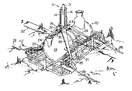
As illustrated, (fIG 2) ~ase 16 is comprised of a
subsea atmospheric ri~er maniFold (SARM) 20 wnic~ is supported on
marine ~ottom 16 3y ~ase template 21. SARM 20 is comprised of
fLuid-tignt pressure hull 22 ~nich enc1Oses manifold piping, valves9
etc. (not snown) and preferaDly a control room for sustaining numan
life in a substantially atmospheric pressure environment. A support
structure 23 called a "strong~ack" has a platform 26, which overlies
hull 22, and a plurality of legs 24 whicn are welded or otherwise
secured to pile guides 25 on template 21. By mounting strongoack 23
directly to template 21, it can ~e seen that ~ull 22 will De
effectively isolated from any forces exerted on platform 26.
Production fluids from a su~merged well or a cluster
of wells 27 (FIG 1) are flowed tnrougn a submerged flowline 28
(FIGS. 1 and 2) and flowed into hùll 22 througn penetrators 29. For
a more detailed description of SARM 2û and support structure 23, see
U.S. Patent 4,398,846.
As Dest seen in FIG.3, platform 26 has an upstanding
mandrel 30 to which riser core 13 is connected Dy a hydraulic
connector 31. Platform 26 also has a plurality of flowline
connector heads 32 (only one shown in FIG. 3) spaced tnereon for
connecting riser flo~lines 14 to respective fluid sources within
null 22 as will De explained Delow. For a more detailed description
3~
F-3422 _ 5 _
of connector head 32 and means for connecting flowlines 14 ~hereto,
see u.S~ Patent No. 4,661,016 of B.F. Baugh and N.N. Panicker~,
iSS~led ~pril 28, 1987.
In previous systems o~ this type, it was proposed to
connect a fluid source within hull 22 to a connector head on
platform 26 by a fixed rigid conduit (not shown) ~hich extended
through the top of hull 22. As water conditions (e.gO currents)
applies forces to riser lO, rigid section ll of riser lO undergoes
limited back and forth cyclic movement from vertical which, in turn,
applies cyclic forces (arrow 13a, FIG. 3) to mandrel 30 and, hence,
platform 26. It can be seen that this rocking or cyclic motion of
platform 26 will continuously stress and relax any rigid conduit
between platform 26 and hull 22 and that such forces will be
concentrated at a fixed point wltni.n a conduit at wnich a conduit is
likely to fail. Also, substantial forces will ~e translated to the
skin of hull 22 where a rigid conduit penetrates the hull which can
also lead to early failure of the system.
In accordance with the present invention, a flex fluid
connecting means 33 is used to connect flowline connector head 32 to
the interior o~ hull 22. Means 33 is comprised of a length of
substantially rigid pipe (e.g. steel pipe) which has a circularly
curved portion 34 therein. Tne upper end of pipe 33 is fixed to
platform 26 and carries connector head 32 thereon. Pipe 33 is
rigidly connected to platform 26 so that there is no slid.ing wear
tnerebetween. The lower end of pipe 33 is fixedly connected to SARM
20 where it penetrates hull 22 ~y welding or by a suitab1e ~1ange (not
shown). The point 35 at which pipe 33 penetrates hull 22 is
preferably offset from the vertical centerline of hull 22 by a
distance d necessary to ~eep pipe 33 out of the bilge water 36 (e.g.
approximately 6" deep at the dee~st point) which is normally present in
hull 22. As shown in fIG. 3, pipe 33 extends substantially ~ertically
after it penetrates hull 22 and is pre~erably loosely passed through
an opening 37 in floor 38 of SARM 20 where it is connected to
valves, etc~ (not shown) within hull 22.
~l~7~3
F-~422 - 6 ~
Circularly curved portion 34 of pipe 3~ is formed so
as to substantially conform to the outer surface o~ hull 22 and is
spaced therefrom so as not to be in contact with hull 22. It can be
seen that as platform 26 is rocked or cycled by the forces applied
through mandrel 30 and riser section 11, the curved portion 34 acts
as a flex means to distriDute these forces throughout the length o~
pipe 33 rather than concentrating these forces at substantially one
fixed point in the connecting means as is the case in rigid
connectors previously proposed for this purpose~