Note: Descriptions are shown in the official language in which they were submitted.
-
~Z75639
This invention relates to a holder assembly
for printed circuit boards such as those used in con-
junction with tote boxes for automatic handling. More
particularly, the invention relates to an adjustable
circuit board holder assembly which is used as a
divider in a tote box and can be infinitely adjusted
to facilitate the robotic selection and handling of
printed circuit boards.
Holding members for printed circuit boards
in the form of clamping devices are known such as indi-
cated in U.S. Patent 3,767,058. Circuit board retainers
are also described in U.S. 3,845,359 wherein compression
screws are utilized in conjunction wi-th springs for
holding the circuit board. In U.S. Patent 4,184,599 a
storage device for holding a plurality of printed cir-
cuit boards between two movable type protions is pro-
vided. An adjustable circuit card retainer is described
in U.S. Patent 4,462,499 wherein a card retaining bracket
is placed in slidable communication with a mounting
bracket so that it is adjustable with respect to the
card.
The positioning of printed circuit boards
for robotic handling is described in U.S. Patent
4,527,222. In this particular patent, an insert in
the form of a frame is placed in the tote box so as to
provide precise locating of the printed circuit boards
in the frame holding device.
The prior art does not provide a circuit
~2`75i~
-- 2
board holder which can effect incremental ad~ustment of a
printed circuit board ~or robotic handling~ In certain
instances, the prior art is either concerned with devices
for connecting or storiny printed circuit boards in
box-like containers. In the instance where an adjustable
circuit board holding device is afforded for the robotic
handling of the printed circuit boards, it does not
provide for incremental adjustment of the printed circuit
board.
It is an aim of the present invelltioll to provide
a printed circuit board holding device which is
incrementally adjustable for use in conjunction with
robotic handling and which preferably can be employed in
conjunction with standard tote boxes.
The present invention therefore provides an
adjustable mounting device adapted to be connected to a
wall surface of a container box and a holding member for
holdiny circuit boards or the like so as to provide for
incremental adjustment of the holding member comprising:
a first member adapted for placement in contact
with said wall surface of said container;
means extending from said first member for
engagement with said wall surface to restrict movement of
said first member in a lateral direction;
first guide way means extending from said first
member;
a second member adapted for connection with said
holding member for articles to be placed in said container;
second guide way means extending from said second
member; and
screw thread means operatively associated with
said first and second members, said screw thread means and
said first and second guide way means constructed and
arranged to effect movement of said second member in a
lateral direction when said first member is restricted in
movement in said lateral direction.
s
s ~
- 2a -
One of the advantages of this invention is that
the circuit board holder of the invention allows for a
simple and quick adjustment of divider devices to fit
various size circuit boards in a snug manner.
Another advantage of this invention is that
circui.t board holders are of a uniform dimension so that
inventory costs are reduced and usage is simplified.
; A
~2~5~
Further, circuit board holdersof the invention
can be manufactured at low cost from readily available
materials and can be easily assembled.
Further features and advantages of the present
S invention will be understood by reference to the follow-
ing description of preferred embodiments of the invention
with reference to the drawings wherein:
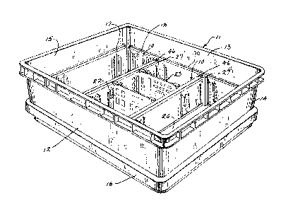
Figure 1 is a top perspective view of two of
the adjustable mounting devices as they are positioned
in tote box.
Figure 2 is a partial top plan view and
partially in horizontal section illustrating the
mounting devices of this invention with the circuit
board positioned there-between.
Figure 3 is a top perspective view showing
one of the adjustable mounting devices attached to the
circuit board holder member which is partially shown.
Figure 4 is a perspective view illustrating
the back o~ the end cap component shown in Fig. 3.
Figure 5 is a view similar to Fig. 3 showing
the assembly of the adjustable mounting device.
Figure 6 is a view in vertical section taken
along line 6-6 of Fig. 2.
Figure 7 is a view in vertical section taken~
along line 7-7 of Fig. 2.
Figure 8 is a view in horizontal section
taken along line 8-8 of Fig. 7.
Figure 9 is a view similar to Fig~ 8 showing
a different position for the detent mechanism.
Figure 10 is a view similar to Fig. 5 illus-
trating an alternative embodiment.
Figure 11 is a view in side elevatiGn showing
the back of the end cap component of Fig. 10~
Figure 12 is a view similar to Fig. 5 showing
yet another alternative embodiment.
Figure 13 is a partial view in vertical
;3~
section showing the latching mechanism of Fig. 12.
The circuit board holder assembly includes
two of the mounting devices shown at lO in Fig. l
positioned in a tote box generally 11. The tote box 11
in this instance has the usual front wall 12, a back
wall 13, side walls 14 and 15 as well as a bo~tom wall
20. It also has a bumper rim 16. This particular
tote box is the subject matter o~ U.S. Patent 4,499~997.
Referring to both Figs. 1 and 2, it is seen
that the circuit board holder face 17 is positioned
against the side wall 15 and another similar ~ut lon~er
circuit board holder face 18 is positioned against the
back wall 13. They are also secured to the inside of
front wall 12 as well as side wall 14 such as by means
of sonic welding. In each instance, the circuit board
holder faces 17 and 18 will have an upper rail portion
such as shown at 30. Each of the holder assemblies lO
include a divider plate 24 which receives the opposing
circuit board holder faces 25 and 75 on each side thereof.
This divider plate will secure the circuit board holder
faces 25 and 75 in a manner to be later described in
conjunction with Fig. 6. The circuit board holder
faces 25 and 75 have the slots 26 and 76 therein for
receiving the printed circuit boards such as 22 and 23.
The holder assemblies 10 include an end cap body 27
having the fIanges 28 and 29 which are receivable in the
slots 32 and 33 of the divider plate member 24. These
slots 32 and 33 are formed from a spacing between the
circuit board holder faces 25, 75 and a central panel
30 section 31 (See Figs. 4 and 5). The divider plate 24
will be retained in the slotted wave form l9 of front
and back wall circuit board holder faces 18 by the end
cap slide 34 having the flange 35 retained in the slots
21. This is best seen in conjunction with Fig. 2.
Turning to Figs. 3-5, as each of the holder
~L~75~
-- 5 --
assemblies lO is the same only one is described in
detail~ The end cap slide 34 is slidably retained in
a frame 36 composing a part of the end cap body 27 which
also has the support wall 37. Projections 38, 39, 40
and 41 extend outwardly from the support wall 37 and
have the engagement surfaces such as 57 for slidable
engagement along the guide ways 52, 53, 54 and 55 of the
end cap slide 34. The support wall 37 has a longitu-
dinally extending slot 69 for receiving the drive shaft
45 as well as a compartment 42 with a support wall 43
for accommodating the screw threads 47 of the shaft 45.
A slotted head portion 46 extends from shaft 45 which
has the intermediary screw threads 47. Connected to
shaft 45 is a slotted portion 49 with two protrusions
50 and 51 extending outwardly and transversely with
respect to the slot 49. These serve as part of a detent
mechanism as will be further explained in conjunction
with the description of Figs. 8 and 9. The end cap
bod~ also has a recess 44 at the top as well as an
associated wall portion 62 for receiving and providing
support to the circular flange 71 of the drive shaft 45.
As best seen in Fig. 4 end cap slide 34 has a rib 67
extending diagonally over the back thereof. This serves
as part of the detent mechanism which is described in
conjunction with Figs. 8 and 9.
Referring to Fig. 6, it is seen that the
circuit ~oard faces 25 and 75 are held in the divider
plate 24 having the opposing T-shaped heads 58 and 59.
Flanges 60, 60a and 72, 72a are spaced from the central
panel 31 to afford slots or tracks 73, 73a, 73b and 73c
so as to receive the inset flanges 61, 61a, 61b and 61c
of the circuit board holder faces 25 and 75.
As best seen in Figure 7, end cap slide 34
includes a threaded rack 64 extending from the rear
thereof and opposite the flange 35. The threaded rack
64 engages the screw threads g7 on the drive shaft ~5
~L27~i3g
- 6 -
as positioned in the compartment 42. The threads 47
will be held captive in the compartment 42 by the wall
surfaces 43 and 73. In this position, the flange 71 is
accommodated in the recess 44 and rests on the wall 62.
(See Fig. 5) At the opposing end, the drive shaft 45
- rests on the support wall 77, which is an extension of
a back wall portion 70 of the end cap body 27. An
extending foot portion 48 provides a standoff which
serves to stablilize the holder assembly 10 in the tote
box 11 and a heel portion 63 provides a support for head
59 so as to space the holder assembly 10 above the bottom
wall 20. This compensates for any warping of the bottom
wall.
As best seen in Figs. 8 and 9, a detent
mechanism, generally 74, is afforded for the drive shaft
45. This is accomplished by a U-shaped compartment 89
formed by a U-shaped wall portion 70 extending from the
back of support wall 37 and the protrusions 50 and 51
extending from the drive shaft 45. These protrusions
50 and 51 engage the projections 66 extending from wall
portion 70 as well as rib 67 extending from the back
of end cap slide 34. This detent mechanism aids in
avoiding undesired turning of the shaft 45 such as
during shipping. ~hen projections 50 and 51 are in the
position shown in Fig. 9, shaft 45 cannot be rotated
without a force being applied. When a rotative force
is applied, projections 50 and 51 engage projection 66
and rib 67 with a compression of slot 49. This effects
sufficient resistance until the projections 50 and 51
are again diagonally positioned.
An alternative embodiment of the holder
assembly is shown in Figs. 10 and 11 designated gen-
erally 80. The end cap slide 81 is similar to end cap
slide 34 except that on the reverse side it has two
parallel ribs 85 and 86 for capturing the nut 83 in
the slot 84 when the nut 83 and the bolt 82 are posi-
127~t;39
-- 7 --tioned in the slot 69 with nut ~3 slidably received
therein. In this instance, end cap body 87 is similar
thereto and has the recess 44 and the wall 62 for
supporting the head 88 of the bolt 82. In other respects,
embodiment 80 is similar to the previously described
embodiment 10 in that end cap slide 81 has the flange
35 for retention in the slots 21 of the wave form 19.
It is also slidably received by the end cap body 87 with
the previously described projections 38-41 engaging
the guide ways 52-55 having the undercuts 56. Flanges
78 and 79 extend from the bac:k of the end cap body 87
for receiving a divider plate 24 in the same manner as
described for flanges 28 and 29 of the end cap body 27.
Referring to Figs. 12 and 13, an additional
embodiment 90 is depicted. This embodiment differs
from the previous one in that instead of a threaded
engagement means for moving end cap body 97 laterally
relative to the end cap slide 91 there is a ratchet
mechanism represented by the arm 92 extending from the
2~ end cap slide 91 having the grooves 93. This arm 92
is biased in a manner to enage the wall 95 provided in
the opening 94 in the end cap body 97 which also is of
a rectangular frame structure 36. It will also be noted
that the support wall 96 of end cap body 97 does not
have a slot but does have the same projections 38-41 for
engaging the slides such as 52, 53 and 55 and their
undercuts 56. It also has the flanges 98 and 99 for
receiving the divider plate 24.
The holder assembly 10 will be better under-
stood by description of its fabrication and operation.
The assembly of the holder assembly generally 10 is best
indicated in conjunction with Fig. 5. Specifically, the
unit is composed of Eour parts: the end cap slide 34,
the drive shaft 45, the end cap body 27 and the divider
plate 24. The drive shaft 45 will be aligned and inserted
through the slot 69 with the shaft 45 seated in the end
~2~5~3~
cap body 27 as shown in Fig. 7. This will be initially
effected by positioning the shaft 45 at a steep angle
with respect to end cap body 27 so the slotted head 46
can be inserted through opening 63 leading into the
recess 44. The next step is to slidably position the
undercuts 56 on the guide ways 52-55 of the end cap slide
34 so as to press fit them together with the engagement
surfaces 57 of the projections 38~41. In this position,
the threads 47 of the projections 38-~1. In this position,
the threads 47 of the drive shaft 45 engage the threaded
rack 64 of the end cap slide 34. Also in this position
the end cap body 27 is ready to engage the divider
plate 24 or holder member. This is effected by positioning
- the flanges 28 and 29 into the slots 32 and 33 of the
divider plate 24. Next is to place two of the holder
assemblies 10 into the box 11 and between the circuit
board holder facas 18 which are positioned on the inside
of the walls 12 and 13. This is effected by placing the
extending flanges 35 into the adjacent slotted wave form
19.
It will be appreciated that the widths of
circuit boards such as 22 and 23 will vary from each
other so that the adjustment to receive their end edge
sections in the slots such as 26 and 76 is critical. To
adjust for these variations in widths, all that is
re~uired is a turning of the drive shaft 45. This would
ordinarily cause the end cap 34 to move in an angular
manner with respect to the end cap body 27 through the
engagement of the screw threads 47 and threaded rack 64.
~owever, the follo~ing factors must be considered. The
flange 35 is now held in the circuit board holder face 18
and in the wave form 19 so that lateral movement is pre-
vented. Also, the factor that the guide ways 52-54 as
well as the projections 38-41 are positioned at an oblique
angle with respect to the flange. These factors will
cause lateral and angular motion of the end cap body 27
~.~75~
with respect to the flange 35 and the front and back
walls 12 and 13. This lateral motion will then allow the
divider plates 24 to move toward or away from the circuit
boards 22 and 23 for adjustment purposes. It will be
appreciated that while lateral motion of the end cap
bodies 27 is effected with respect to the flanges 35,
they are held stationary with respect to lateral motion,
some upward and downward motion of the end cap slide 34
is effected. However, the lateral motion of the end cap
bodies 27 is effected due to the previously described
i oblique angle of the guide ways 52-55 and the projections
38-41. This upward or downward motion will not be a
factor as to the divider plates 24 and the circuit boards
22 and 23 which are positioned on the heel 63 of the end
cap body 27 by their own weight and will not be raised or
lowered. In the event the circuit boards 22 and 23 and
the holder faces 25 and 75 should attempt to be raised,
a slight force on the tops of circuit boards 22 and 23
will cause them to be released from the holder faces and
positioned against the heel 63 o~ the end cap body 27
or the bottom wall 20 in the absence thereof.
The operation of embodiments 80 and 90 is sub-
stantially the same as previously described for embodiment
10. The same lateral motion of the end cap bodies 87 and
97 will be effected when the flanges 35 are restrained
from lateral movement in-the slots 21 of the wave form 19.
In the instance of the embodiment 80 the turning of the
bolt 82 with the capture of the nut 83 in the end cap
slide 81 will effect the lateral movement of the end cap
body 87 and the divider plates 24. In the instances of
the embodiment 90, a movement of the rachet arm 92
inwardly or outwardly with respect to the end cap body
97 will effect the same lateral motion of the end cap body
97 and the clivider plates 24.
The preferred materials for injection molding
of the end cap slides 34, 81 and 91, the drive shaft 45,
56;3~3
-- 10 --
the bolt 82 and the nut 83 as well as the end cap
bodies 27, 87 and 97 is an acetal plastic. However,
other plastic materials such as nylon or A~B.S. can be
employed. In this instance, the circuit board holder
faces 25 and 75 are molded from a polypropylene material
whereas the divider plate 24 is extruded aluminum. Other
lightweight plastic and metal materials could be sub-
stituted.
A slotted head 46 is provided on the shaft 45.
This affords engagement with a screw driver. If desired,
a slotted tab could be subst:ituted for finger engagement
with a portion of the tabs being removed to provide a
slot for a screwdriver.
In the foregoing description, the detent
mechanism is employed in conjunction with the protrusions
50, 51 and the slot 49. While this feature is advanta-
geous in preventing the screw threads 47 from turning
during transportation, this feature could be eliminated
and still obtain the advantages of the device for this
invention. A compartment 42 is provided for the threads
47 and allows for expansion therein should the end cap
slide be forced against a restraining surface such as the
bottom wall 20 of the tote box 11 or a surface of the
end cap body. This also could be eliminated. An oblique
angle of approximately 30 is preferred for the slide
guide ways 52-55. Any angle which will afford a lateral
movement of the end cap body 27 could be utilized. While
the holder device 10 has been shown in conjunction with
a facing board 25 on each side of the holder 2~. This
is not essential and the advantages of this invention
could be accomplished with only a single facing board
being employed on one side. Also, while two holder
devices have been illustrated, some of the advantages of
this invention could be accomplished by using a non-
adjustable divider holder panel in combination with anadjustable one.
It will thus be seen that through the present
invention there is now provided a holder assembly for
circuit boards which is infinitely adjustable and thus
lends itself to robotic handling. The holder assemblies
provide for fast and efficient placement in the container
as well as versatility in accommodating various types of
facing board holders. The holder assemblies of this
invention are adaptable to being utilized as adjustable
divider plates allowing for simple, quick adjustment of
the dividers to accommodate various widths of circuit
boards snugly with a single clivider plate. The holder
assemblies are of uniform constructions thus reducing
inventorying of different assemblies.