Note: Descriptions are shown in the official language in which they were submitted.
METHOD A~D APPARAT~S FOR EVACUATING
AND FILLING HEAT PIPES AND
SIMILAR CLOSED VESSELS
1 BACKGRO~ND
This invention is directed to a method and
apparatus for evacuating and filling heat pipes and similar
closed vessels where the vessel has an opening with a valve
therein which can be sealed against the apparatus while the
vessel is evacuated and filled. Thereafter, the valve is
closed while the opening is still sealed.
Heat pipes are closed vessels having a chamber
therein. There is a heat input portion and a heat output
portion of the heat pipe. ~luid in the chamber circulates
and principally transfers heat by the heat of vaporization
and condensation, coupled with mass transfer of vapor and
liquid, The heat pipe utilizes evaporation and condensation
o the fluid and achieves efficient heat transfer by mass
transfer of the fluid. The heat pipe working fluid may be
water, ammonia, methanol or other alcohols, or halogenated
hydrocarbons, such as freon. The particular working fluid
and the quantity of that working fluid which relates to the
working pressure of the heat pipe are chosen in accordance
with the range of temperatures expected to be encountered
in operation of the heat pipe in accordance with material
compatibility properties.
The working fluid in th* chamber of the heat
pipe is thus critical with respect to both quantity and
quality of the fluid fi~ll or "charge". To achieve the
correct fluid fill or "charge", present heat pipes are
provided during their manufacture with an externally pro-
truding filling tube which is in communication with the
chamber. After the physical manufacturing is completed,
the heat pipe is processed by charging it with the correct
;Q~;~
1 fluid. First, the fill tube is connected to a vacuum
source to evacuate the original materials from the heat
pipe chamber and, thereafter, the proper amount of the
select~ed working fluid is charged through this fill
tube. After filling, the tube is closed by crimping
and welding to maintain the closed integrity of the
heat pipe chamber. This method of charging the heat
pipe is time-consuming, is a process which must be
critically performed in order to be successful, is
permanent, is difficult to achieve repeatability, and
cannot be used for a recessed fill port. Therefore,
there is need for a method and apparatus for evacuating
and filling heat pipes and similar closed vessels so
that the evacuation, illing and sealing of the vessels
are quickly and reliably accomplished,
:' :
SUMMARY
In order to aid in the understanding of this
invention, it can be stated in essentially summary form
that it is directed to a method and apparatus for
evacuating and filling heat pipes and similar closed
vessels. The filling apparatus has an external seal
against which the filling port of the heat pipe is
clamped. The method includes the evacuating and filling
of the heat pipe while the port is clamped against the
seal. The heat pipe is provided with an internal valve
in its filling port, and the valve is closed through
the filling passage while the heat pipe remains sealed
to the filling apparatus.
It is, thus, a purpose and advantage of an aspect of this
invention to provide a heat pipe design which does not
require an external supplementary filling tube, but
instead has a fil7ing port with an internal valve
therein so that the valve can be closed for seallng with
'~
:'
, ~ .~..
no external protrusion from the hPat pipe structure.
It is a purpose and advantage o~ an aspect of t~is
invention to provide a method and apparatus for charging
heat pipes which is suitable for high volume processing,
wherein evacuation, filling and closing of the heat pipe
can be readily accomplished with the heat pipe clamped
in a single fixture loaation.
It is a purpose and advantage of an aspe~t of this
invention to provide a heat pipe which has a reopenable
valve in its ~illing port so that the heat pipe can be
repaired and reprocessed repeatedly, as required,
without the need to open or replace a crimped tube.
It is a purpose and advantage of an aspect of this
invention to pro~ide a heat pipe of simplified design
having the filling port a~ part of the inherent
structurs of the heat pipe, thus reducing the cost o~
the heat pipe and the cost of the heat pipe filling
steps due to the readily manufactured design and the
ease and integrity of the filling process.
: 20 An aspect of the invention is as follows:
An elongated hea~ pipe comprising:
a metal wall defining a closed heat pipe chamber, a
substantially planar face on said wall;
a passage extending through said heat pipe wall to
provide access t~ said chamber in said heat pipe to
provide a filling port for said heat pipe, said passage
having a counter bore therein into said heat pipe from
said planar face, a threaded section recessed below said
planar face; and
valve means in said pa~sage for selectively
closing off said passage, said valve means including a
substantially square seat in said recess between said
threaded seation and sai~ counter bore, said valve means
including a metal valve member having a threaded end
threaded into said passage, said valve member having a
conical shoulder configured to sealingIy engage on said
a~
.....
valve seat in said valve passage, a non-round receptacle
in said metal valve member con~igured for engagement by
a corresponding non-round driver to rotate said valve
member with respect to said heat pipe so that said valve
member can be screwed into said passage to forcibly
engage said shoulder on said valve seat in metal-to-
metal eng,ag~ment to close said passage, said valve
member having a bore therethrough from said threaded ~nd
terminating on the side of said shoulder toward said
threaded end, said valve memher when closing said
passage being positioned within said passage recessed
from said external surface so as to provide a ~lush
surface on said ~ace for permitting evacuation of said
chamber and filling of said chamber with a selected
amount of heat pipe fluid without valve structure
extending beyond said face.
Other purposes and advantages of this invention
will become apparent from a study of the following
portion of this specification, the claims and the
attached drawings.
~ BRTEF DES~RIPT~O~ OF TH~ DRA~INGS
:~'
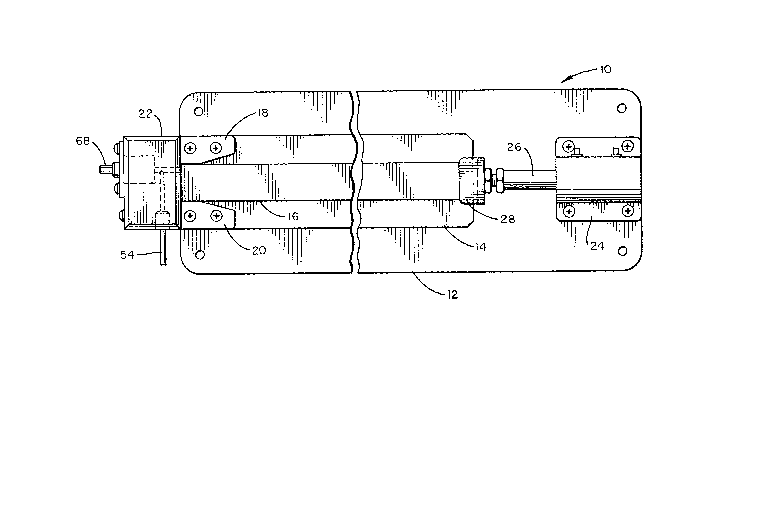
FIGURE 1 i~ a plan view of the apparatus of this
invention, which holds a heat pipe in position during
the filling process.
FIGURE 2 is a side-elevational view of the
apparatus shown in FIGURE 1.
FIGURE 3 is an enlarged section taken generally
along the line 3-3 of FIGURE 2, with parts broken away.
: `
1 DESCRIPTION OF THE PREFERRED EMBODIMENT
The apparatus for evacuating and filling heat
pipes ~nd similar closed vessels in accordance with
this invention is generally indicated at 10 in FIGURES
1 and 2. The apparatus has a baseplate 12 upon which
is secured table 14~ Table 14 is for the support of
a heat pipe 16 thereon. As is seen in FIGVRES 1 and
2, the heat pipe 16 is a long, narrow, rectangular
structure which lies upon the top of ~able 14 and
extends somewhat beyond the right end thereof. Guidas
18 and 20 are attached to the top of the table 14 at
; the left end thereof and are spaced apart to receive
the end of heat pipe 16 therebetween. Block 22 is
secured on the left end of table 14 and extends ~here-
above to act as a stop for the left end of heat pipe
16, among other functions. Clamp 24 is mounted on the
right end of baseplate 12 and has thrust bar 26 extending
therefrom. Thrust finger 28 is mounted on the end of
the thrust bar 26 to engage the right end of the heat
pipe 16. When clamp 24 is actuated, it applies a
leftward force which holds the left end of heat pipe 16
against the stop face 30 (see FIGURE 3) of block 22.
For convenience of illustration, clamp 24 ls shown as a
` 25 cylinder and piston clamp, for which the thrust bar 26
is the piston rod. By controlling the fluid pressures
against the clamp piston (not shown1, the amount of
force on the heat pipe 16 can be controlled. Other
types of cla~nping structures, such as toggle, lever arm
and spring clamps, could alternatively be employed.
A portion of the heat pipe 16 is shown in more
detail in FIGURE 3. Heat pipe 16 is a rectangular
structure having a chamber 32 therein. The chamber 22
extends substantially the length of the heat pipe 16
and may have wicks or other structures therein to aid
~, .
76a~
1 in fluid flow by capillary action. The le~t end face
34 of heat pipe 16 is planar to lie against the planar
stop face 30 when thrust into that position by the
clamp 24. Fill port 36 extends rom the face 34 into
S chamber 32, past seat 38. Toward the interior of the
heat pipe 16 from the seat 38, the port 36 is threaded
to receive threaded valve member 40. Valve member 40
has a shoulder 42 thereon which serves as a valve disc
and which engages against seat 38 to form a cold weld
thereagainst when the valve member 40 is fully screwed
down into the port 36~ Valve member 40 has axial bore
44 extend.ing from chamber 32 to cross bores 46, which
are just beyond shoulder 42 in the direction of chamber
32. These bores 44 and 46 permit fluid flow between
the chamber 32 and fill port 36 when the valve member
~ 40 is off the seat 38, without the requirement of fluid flow past the threads of the valve member 40. At its
.~ outer face, valve member 40 is provided with a hexagonal
recess 48.
The guides 18 and 20 are positioned so that when
~: the heat pipe 16 is placed therebetween, the fill port
36 receives nose 50 extending from the stop face 30.
It will be noted that the outer end of the valve member
40 is recessed from the stop face 30 and O-ring 52
seals around the fill port 36. Process tube 54 is
connected through a vacuum control valve (not shown) to
a vacuum source (not shown) and is connected through a
fill fluid control valve ~not shown) to a source of
heat pipe fil}ing fluid (not shown). Process tube 54
communicates with passage 56 which, in turn, communicates
with passage 58 which opens through nose 50 to the fill
port 36. When the valve member 40 is off of its seat
38, process tube 54 is connected to the interior chamber
32 of heat pipe 16. When the valves on the process
tube 54 are controlled, the chamber is first evacuated
.
z
1 and then a preselected amount of the desired heat pipe
fluid is introduced into the chamber 32.
Piston 60 is mounted in cylindrical chamber 62
and is sealed therein by means of O-rings 64 and 66.
It is rotatable in its chamber 62 by means of hex shank
68 which extends leftward, exteriorly of block 22. The
piston 60 is maintained in its chamber 62 by means of
cover plate 70 screwed on the left end of block 22.
~ex driver 72 engages a hexagonal recess in the right
end of piston 60, extends through passage 58, is spaced
inwardly from the sidewall~ thereo~, and engag0s the
hex recess 48 in valve member 40. Thus, by use of a
hex wrench tnot shown) to rotate the hex shank 68, hex
driver 72 rotates valve member 40 in the port 36. In
this way, the valve member 40 is rotated to screw down
to a closed position with its shoulder 42 against seat
38 when filling is complete. Hence, valve closing is
accomplished while the area of the fill port 36 is
subjected to the proper pressure of the fill fluid, and
is protected from the ambient air. From the foregoing
it will be readily apparent that the heat pipe 16 can
be quickly put in place, evacuated, filled with the
proper amount of the proper fluid, and its chamber 32
closed without changin~ stations or connections, The
; 25 heat pipe 16 i5 quickly locked against a leak-tight
seal S2 during all of the steps of processing, i.e.,
the evacuation, filling and closing of the fill port
36. Each step is completed while the heat pipe 16 is
subjected to the proper environment. Because these
steps are accomplished at the same station, each step
can be more quickly and reliably accomplished.
Furthermore~ it will be understood that the heat
pipe fill port 36 is integral in the design of the heat
pipe 16 and it is not a supplemental structure. The
employment of a valve member 40 has an additional
~, :
. .
'~~~'` ~.æ7~x
1 advantage in that the heat pipe 16 can be reprocessed,
should for some reason there be improper fluid in the
heat pipe 16. By returning the heat pipe 16 to its
filling apparatus 10, the valve member 40 can be opened,
the chamber 32 of the heat pipe 16 evacuated, and the new
- fluid installed. Thus, there is an easily managed way of
reprocessing such heat pipes.
This invention has been described in its
presently contemplated best mode, and it is clear that
it is susceptible to numerous modifications, modes and
embodiments within the ability of those skilled in the
art and without the exercise of the inventive faculty.
Accordingly, the scope of this invention is defined by
the scope o the ~ollo~ing clalms.