Language selection

Search

Patent 1276909 Summary

Third-party information liability

Some of the information on this Web page has been provided by external sources. The Government of Canada is not responsible for the accuracy, reliability or currency of the information supplied by external sources. Users wishing to rely upon this information should consult directly with the source of the information. Content provided by external sources is not subject to official languages, privacy and accessibility requirements.

Claims and Abstract availability

Any discrepancies in the text and image of the Claims and Abstract are due to differing posting times. Text of the Claims and Abstract are posted:

  • At the time the application is open to public inspection;
  • At the time of issue of the patent (grant).
(12) Patent: (11) CA 1276909
(21) Application Number: 1276909
(54) English Title: SCREW-TYPE SAFETY CAP
(54) French Title: CAPUCHON VISSANT DE SURETE
Status: Expired and beyond the Period of Reversal
Bibliographic Data
(51) International Patent Classification (IPC):
  • B65D 55/12 (2006.01)
  • B65D 41/34 (2006.01)
(72) Inventors :
  • LUKER, EDWARD (United States of America)
  • WRIGHT, DAVID M. (United States of America)
(73) Owners :
  • SUNBEAM PLASTICS CORPORATION
(71) Applicants :
  • SUNBEAM PLASTICS CORPORATION (United States of America)
(74) Agent: BORDEN LADNER GERVAIS LLP
(74) Associate agent:
(45) Issued: 1990-11-27
(22) Filed Date: 1985-06-04
Availability of licence: N/A
Dedicated to the Public: N/A
(25) Language of filing: English

Patent Cooperation Treaty (PCT): No

(30) Application Priority Data:
Application No. Country/Territory Date
707,205 (United States of America) 1985-03-01

Abstracts

English Abstract


A-412 SUNBEAM
ABSTRACT OF THE DISCLOSURE:
A threaded closure having both a tamper indicating
and a non-backoff feature which locks the closure to a con-
tainer to avoid unwanted loosening. The closure takes the
form of a one piece cylindrical cap with an inwardly directed
bead at its open end. The cap bead engages a complimentary
bead on the neck of the container as the cap is screwed onto
the container, and the cap bead snaps over the container bead
to form a non-backoff seal. The cap has a tamper indicating
band attached to its lower end by frangible webs. The band
and container have complimentary stop means which coact to
restrain movement of the band when the cap is unthreaded,
fracturing the frangible webs giving an indication of tampering
or initial opening.


Claims

Note: Claims are shown in the official language in which they were submitted.


THE EMBODIMENTS OF THE INVENTION IN WHICH AN EXCLUSIVE PROPERTY OR
PRIVILEGE IS CLAIMED ARE DEFINED AS FOLLOWS:
1. A screw-type safety cap for use on a container having a
threaded neck, an outwardly projecting bead below said thread and
stop means below said bead, said cap comprising, in combination:
a flat top;
a cylindrical skirt portion depending from said top having
internal threads complementary to said container threads and having
an inwardly projected bead at its bottom edge:
a tamper indicating band spaced from said bottom edge of said
cylindrical skirt portion and connected thereto by a plurality of
circumferentially spaced axially extending frangible webs, said
band having stop means cooperating with the stop means on said
container;
whereby as said cap is assembled to a container, said band and
container stop means contact each other without fracture of said
webs snapping said skirt bead over said container bead;
and when said cap is unthreaded from said container, said band
and container stop means cooperate to resist relative movement
therebetween causing fracture of said frangible webs leaving said
tamper indicating band on said container after said cap has been
removed.
2. The screw-type safety cap according to Claim 1 wherein said
stop means includes an inwardly projecting bead at the free end of
the tamper indicating band which cooperates with stop means on said
container which includes a second outwardly projecting bead.
3. The screw-type safety cap according to Claim 2 wherein the
diameter of said tamper indicating band is larger than the diameter
of said cylindrical skirt portion.
4. A screw-type safety cap according to Claim 1 wherein stop
means includes a plurality of inwardly projecting ratchet teeth
PAT 9997-1

extending around the inner periphery of said band which cooperate
with the stop means on said container which includes a plurality of
ratchet teeth on said container.
5. The screw-type safety cap according to Claim 4 wherein the
diameter of said tamper indicating band is larger than the diameter
of said cylindrical skirt portion.
6. A screw-type safety cap for use on a container having a
threaded neck, and outwardly projecting bead below said threads and
stop means below said bead, said cap comprising, in combination:
a flat top;
a cylindrical skirt portion depending from said top having
internal threads complementary to said container threads and an
inwardly projecting bead at its bottom edge;
a tamper indicating band spaced from the bottom edge of said
cylindrical skirt portion and connected thereto by a plurality of
circumferentially spaced axially extending frangible connecting
webs, with spaces between adjacent webs defining slot areas, said
band having a diameter larger than the diameter of said cylindrical
skirt portion and having stop means cooperating with the stop means
on said container:
the bottom edge of said cylindrical skirt portion and top of
said tamper indicating band having parallel planar driving surfaces;
whereby as said cap is assembled to a container, the tamper
indicating band passes over the container threads and the container
bead without interference and, as the cap is screwed onto the
container, the engagement of the skirt bead with the container bead
swells the cylindrical skirt portion to align said planar driving
surfaces and at the same time the band stop means engages the
container stop means providing frictional resistance which moves
the planar driving surface into engagement collapsing said web and
providing axial movement of said band without relative rotational
movement between said band and said cylindrical skirt portion while
snapping said skirt bead over said container bead;
PAT 9997-1
11

and when said cap is unthreaded from said container, said band
and container stop means cooperate to prevent relative rotation
therebetween while said planar driving surfaces are disengaged
causing fracture of said frangible webs leaving said tamper
indicating band on said container after said cap has been removed.
7. The screw-type safety cap according to Claim 6 wherein stop
means includes an inwardly projecting bead at the free end of said
tamper indicating band which cooperates with stop means on said
container which includes a second outwardly projecting bead.
8. The screw-type safety cap according to Claim 6 wherein said
stop means includes a plurality of inwardly projecting ratchet
teeth extending around the inner periphery of said band which
cooperates with stop means on said container which includes a
plurality of ratchet teeth on said container.
9. The screw-type safety cap according to Claim 7 wherein the
planar driving surface on said bottom of said cylindrical skirt
portion and the top of said tamper indicating band includes a
plurality of drive platforms axially extending into said slot areas
with diametric planar ends to engage the other of said parallel
driving surfaces.
10. The screw-type safety cap according to Claim 9 wherein said
drive platforms are located on the top of said tamper indicating
band extending axially upward with diametric planar ends which
engage the planar driving surface on the bottom of said cylindrical
skirt portion.
11. The screw-type safety cap according to Claim 10 wherein the
plurality of platforms comprises eight equally spaced platforms
extending around the periphery of said tamper indicating band.
12. The screw-type safety cap according to Claim 11 in which
PAT 9997-1
12

the plurality of circumferentially spaced axially extending
frangible connecting webs include eight webs with said drive
platforms being individually located in the slot areas between said
webs.
13. The screw-type safety cap according to Claim 6 wherein said
skirt bead includes a plurality of equally spaced bead segments
extending around the periphery of said cylindrical skirt portion.
14. The screw-type safety cap according to Claim 13 wherein
said frangible connecting webs are located in each of the spaces
between said bead segments.
15. The screw-type safety cap according to Claim 14 wherein the
inner surface of said webs are aligned with the inner surface of
said tamper indicating band.
16. The screw-type safety cap according to Claim 14 further
including axial extending recessed teeth in the inner surface of
said cylindrical skirt portion adjacent said connecting webs, both
being located in the spaces between bead segments.
17. The screw-type safety cap for use on a container having a
threaded neck and spaced upper and lower outwardly projecting beads
below said threads, said cap comprising, in combination:
a flat top;
a first cylindrical skirt portion depending from said top and
having internal threads complementary to said container threads:
a second cylindrical skirt portion having a larger diameter
than said first cylindrical skirt portion
13

A-412 SUNBEAN
and depending therefrom with an inwardly projecting bead
at its free end;
a tamper indicating band spaced from the bottom
of said second cylindrical skirt portion and connected
thereto by a plurality of circumferentially spaced axially
extending frangible connecting webs, the space between
adjacent webs defining open slot area, said band having
a diameter larger than the diameter of said second cylin-
drical skirt portion and having an inwardly projecting
bead at its free end;
the bottom of said second cylindrical skirt por-
tion and the top of said tamper indicating band having
parallel planar driving surfaces;
whereby, as said cap is assembled to a container,
the tamper indicating band passes over the container threads
and upper container bead without interference, and, as the
cap is screwed onto the container, the engagement of the
skirt bead with the upper container bead swells the second
cylindrical skirt portion to align said planar driving
surfaces and at the same time the band bead engages the
lower container bead providing frictional resistance which
moves the planar driving surfaces into engagement collapsing
said webs and providing axial movement of said band without
relative rotational movement between said band and said
second cylindrical skirt portion to snap said band bead
over said lower container bead while snapping said skirt
bead over said upper container bead;
and when said cap is unthreaded from said con-
tainer, the engagement of the band bead with the lower con-
tainer bead resists relative axial movement therebetween,
14

A-412 SUNBEAM
and, as the planar driving surfaces are disengaged, fracture
of said frangible webs is caused leaving said tamper indi-
cating band on said container after said cap has been
removed.
18. The screw-type safety cap according to
Claim 17 wherein said skirt bead includes a plurality of
spaced apart segments extending around the periphery of
said second cylindrical skirt portion with said webs
occupying the spaces between adjacent segments.
19. The screw-type safety cap according to
Claim 18 wherein said skirt bead comprises eight equally
spaced segments having eight equally spaced webs in the
spaces between each segment.
20. The screw-type safety cap for use on a
container having a threaded neck and outwardly projecting
bead below said threads and a plurality of equally spaced
ratchet teeth extending around the neck below said bead,
said cap comprising, in combination:
a flat top;
a first cylindrical skirt portion depending from
said top having internal threads complimentary to said
container threads
a second cylindrical skirt portion having a
larger diameter than said first cylindrical skirt portion
and depending therefrom with an inwardly projecting bead
at its free end;
a tamper indicating band spaced from the bottom
of said second cylindrical skirt portion and connected
thereto by a plurality of circumferentially spaced axially
extending frangible webs, said band having a diameter

larger than the diameter of said second cylindrical skirt
portion and having a plurality of inwardly projecting
ratchet teeth extending around the inner periphery of said
band adapted to coact with the ratchet teeth on said con-
tainer;
whereby as said cap is assembled to the container
and tamper indicating band passes over the container threads
and the container bead without interference, and as the
cap is screwed onto the container, the ratchet teeth on said
band contact and slide over the ratchet teeth on said con-
tainer without generating sufficient frictional resistance
to cause fracture of said webs snapping said skirt bead
over said container bead;
and when said cap is unthreaded from said container,
the ratchet means on said band and container cooperate to
resist relative rotation therebetween, causing fracture of
said frangible webs leaving said tamper indicating band
on said container after said cap has been removed.
21. The screw-type safety cap according to
Claim 20 having eight equally spaced ratchet teeth extending
around the inner periphery of said band which selectively
engage four equally spaced ratchet teeth on said container.
22. The screw-type safety cap according to
Claim 20 wherein each of said ratchet teeth on said band
have an inner face formed integral with the inner face of
each of said plurality of axially extending frangible webs.
23. The screw-type safety cap according to
Claim 22 wherein each of said axially extending frangible
16

A-412 SUNBEAM
webs is formed integral with and has its inner face in
alignment with the inner surface of said second cylin-
drical skirt portion.
17

Description

Note: Descriptions are shown in the official language in which they were submitted.


A-412 SUNBEAM
~L276~
This inven~ion relates to safety closures, and
more parLicularly, to a tamper indicating closure which
indicates to the observer that the container-closure package
has not been opened or that it has been opened or been
S tampered.
There are a wide variety of safety closures which
indicate to a perspective purchaser by the condition of the
package whether or not it has been opened or tampered. One
of the most improtant criteria indesigning such a closure,
is to provide one that can be applied to the container with-
out destroying the indicia intended to act as the tamper
indicator. This is particularly true where the -tamper
indicator is a ring or band attached to a cap by frangible
bridges or webs, and high speed packaging equipment is used.
When the closure is of the screw-type, the tamper
indication is usually activated when an unscrewing or un-
threading torque is applied to open the package. Where
frangible webs are used, the opening torque is designed to
cause fracture or breaking of the frangible webs. It is,
therefore, a paramount concern to prevent web breakage when
a torque of similar magnitude is used to apply or thread the
closure onto the container.
, With screw-type fastening, it is often desirable
to provide a non-backoff freature which prevents accidental
and undesirable unthreading of the closure from the container
and that will retain the package seal even if the closure is
partially unthreaded. Combining such a non-backoff feature
with a tamper indicating feature further complicates the
design since the non-backoff feature usually requires addi-
tional -threading or tightening torque which increases the
danger of fracturing the frangible webs during the initial
tightening process.

6~9
It is, therafore, an object of this invention to provide
a screw-type safety closure having tamper indicating means.
It is another object of this invention to provide a
screw-type closure having a non-backoff feature to prevent
accidental unsealing of the closure from the container.
It is a further object of this invention to provide a
screw-type safety closure combining a tamper indicating means with
a non-backoff feature which functions after the initial opening of
the package and the function of the tamper lndicating means has
O been fulfilled.
The objects of this invention are accomplished by a
single piece closure taking the form of a threaded cap having a
flat top and a cylindrical skiet portion which extends from the
top and has internal threads which are complementary to the
container threads. In a preferred embodiment a second cylindrical
skirt portion has a larger diameter than the first mentioned
threaded skirt portion and extends downwardly therefrom
terminating in an inwardly projecting bead or flange at its free
end. This skirt bead cooperates with a complementary bead on the
O container below the threads to form a non-backoff snap lock. A
cylindrical tampeL indicating band is spaced from bhe bottom of
the second cylindrical skirt portion and is connected to it by a
plurality of circumferentially spaced axially extending feangible
connecting webs so that the spaces between the webs define slot
areas. The tamper indicating band is a larger diameter than the
second cylindrical skirt portion from which it depends and it has
stop means located at its lower end which in one embodiment takes
the form of a second inwardly projecting bead which cooperates
with a second bead beneath the first bead on the container to form
O a friction generating surface and a snap lock for the container
and closure package in its

A-412 SUNBEAM
original, as filled, condition. In this embodiment, the
bottom of the second cylindrical skirt has a planar driving
surface which cooperates with a parallel planar surface on
the top of the tamper indicating band. In one e~bodiment
the planar surface on the top of -the tamper indicating band
is formed by a plurality of axially extending projections
with flat tops forming a drive platform extending into the
slot areas between each connecting web. These drive platforms
could be formed on the bottom of the second cylindrical skirt
portion to cooperate with a planar surface on the top of the
tamper indicating band.
When the cap is assembled to the container, the
tamper indicating band passes over the container threads and
the first container bead without interference, and as the
cap is screwed onto the container, the engagement of the skirt
bead with the container bead swells or pushes out the second
cylindrical skirt portion to align the driving platforms on
one member with the planar driving surface on the other member.
At the same time, the stop member or bead at the bottom of the
tamper indicating band engages the stop or lower bead on the
container to provide frictional resistance which moves the
planar driving surfaces into engagement with each other col-
lapsing the webs and providing axial movement of the bands
without relative rotational movement which would tend to
shear the webs. The tightening process is complete when the
non-backoff bead at the end of the second cylindrical skirt
portion snaps over the bead on the container and the stop
bead on the tamper indicating band snaps over the lower bead
on the container.
When the cap is unthreaded from the container, the
band and container stop beads or flanges cooperate to prevent
relative axial movement therebetween, and since the planar

-~12 SUNsE~M
~1.27~9
driving surfaces are disengaged from each other, the frangi-
ble webs are fractured which leaves the tamper indicating
band on the container after the cap has been removed.
In a second embodiment, the stop means on the
tamper indicating band takes the form of a plurality of
equally spaced ratchet teeth which extend around the peri-
phery of the band which cooperates with the stop means on the
container which includes a plurality of ratchet teeth on the
container. In the tightening process the cammed or sloped
surface of the cooperating ratchet teeth on the band and the
container allow contact with each other without fracture of
the frangible webs. When the band is unthreaded from the
container, the flat stop surfaces of the ratchet teeth on
the band arld container cooperate to prevent relative rotation
causing fracture of the frangible webs as in the first embodi-
ment.
The preferred embodiments of the invention are
illustrated in the drawing in which:
FIG. 1 is a fragmentary perspective view of the
closure and the container to which the closure is applied
embodying the present invention;
FIG. 2 is a fragmentary perspective view in section
showing the cap applied over the container neck as the cap
beads begin to make contact with the container beads;
FIG. 3 is a partial perspective view slmilar to
FIG. 2 showing the cap skirt bead and the tamper indicating
band bead in contact with the container beads as the second
cylindrical skirt portion is pushed outward aligning the
skirt with planar driving platEorms;
FIG. 4 is a partial side elevation in cross section
showing the skirt bead and band bead in full engagement with
the container beads;

A-412 SUNsEAM
"
1~6~
FIG. 5 is a fra~mentary perspective view in
section showing another embodiment of the invention;
FIG. 6 iS an enlarged fragmentary perspective
view in sec-tion showing -the alignment of the inner web sur-
face with the inner cap skirt surface and the inner tamper
indicating band surface;
FIG. 7 is a top plan view of the tamper indicating
band of FIG. 5 showing -the details of the ratchet teeth;
FIG. 8 is an enlarged view showing the detdils of
one of the teeth shown in FIG. 7;
FIG. 9 is a top view of the container to which
the closure of FIG. 5 is applied showing the details of the
ratchet teeth.
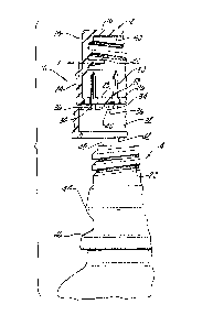
ReEerring to FIGS. 1 through 4, closure 10 is shown
as a one piece screw-cap 12 designed for application to
threaded container 14. Screw-cap 12 is cup shaped having a
flat top 16 and first cylindrical skirt portion 18 having
internal threads 20 for engagement with complimentary con-
tainer threads 22. Cap 12 flares out from the first
cylindrical skirt portion 18 to a second cylindrical skirt
portion 24 having an inwardly projecting bead 26 which is
segmented or divided into a plurality of segment sections 28
to accommodate -therebetween recessed unscrewing teeth 30
used in the molding process and connecting webs 34. Spaced
from the bottom of the second cylindrical skirt portion 24
is tamper indicating band 32 formed integrally as part of
the cap and joined to the second skirt portion by frangible
connecting webs 34, the spaces between the adjacent webs 34
defining slot areas 36. Band 32 has a larger diameter than
the second skirt portion 24, being offset outwardly as shown
by the dimension X in FIG. 1. Planar drive platforms 33 are
formed on the top of tamper indicating band 32 by upwardly

A~412 SUNBE~M
. ,. ~
3LZ76~19
extending axial projections in slot areas 36. These drive
platforms 38 engage the flat planar surface 40 at the bottom
of second skirt portion 24 in the assembly process, planar
platforms 38 being parallel to planar surface 40. The band 32
has inwardly projecting bead 42 at its lower end. Container
14 has upper outwardly projecting bead 44 and lower outwardly
projeçting bead 16 which engage and coact with skirt bead 26
and band bead 42, respectively. As screw-cap 12 is assembled
to container 14, tamper indicating band 32 passes over container
threads 22 and the upper container bead 44 without interference.
As cap 12 is screwed onto container 14, cap threads 20 engaging
container threads 22, skirt bead 26 engages the upper container
bead 44 to swell or push outwardly the second cylindrical skirt
portion 24 so as to align the planar drive surface ~lO a~ the
bottom oF skirt 24 with drive platforms 38 on the top of
tam2er indicating band 32 as shown in FIGS. 2 and 3. At the
same time, band bead 42 engages the lower container bead ~6
providing frictional resistance which moves the planar driving
platforms 38 into engagement with planar driving surface 40
which collapses webs 34 into the open slot areas 36 as best
seen in FIG. 3. Thereafter, the threading, clockwise rotation
of cap 12 will be transmitted to band 32 without relative
rotational movement between cap 12 or lower skirt portion 34
and band 32. As the skirt bead 26 passes over upper container
bead 34, it will snap onto the container to provide a non-backoff
coacting,seal between the two beads as shown in FIG. 4. At
the same time, or at substantially the same time, the skirt
bead 42 will snap over lower container bead 46 likewise forming
a coacting seal. The non-backoff coaction between skir~:
3~ bead 26 and upper container bead 44 will maintain a tight
seal with the upper surface 48 of container 14 seating against
the inside surface 50 of flat cap top 16. This seal will be

A~412 SUNBEAM
~;Z7~
retained during the initial rotation of cap 12 in an unthreading,
counterclockwise direction.
As shown in FIG. 4 in its initial, as filled, sealed
position, skirt bead 26 is snapped over upper container bead
44 forming a non-backoff seal, and tamper indicating band
bead 42 is snapped over lower container bead 46 forming a
tamper resistant connection. Frangible webs 34 straighten out
from the folded position shown in FIG. 3 to the vertical
position shown in FIG. 4. When the cap 12 is unthreaded from
the eontainer 14, the coaction of band bead 42 with container
bead 46 resists upward movement of band 32 while the planar
driving surfaces 38 and 40 are disengaged causing fracture
of the frangible webs 34 leaving the tamper indicating band 32
on the container as the cap is removed. While the drive plat-
forms 38 are shown as extending upwardly from tamper indicating
band 32 to engage the flat planar surface 40 at the bottom of
eap skirt 24, the drive surfaces could extend downwardly from
the seeond eap skirt portion 24 to engage a flat planar sur-
face on the top of band 32.
2~ In t~e embodiment shown in FIG. 5 - 9 a different
stop is used on tamper indicating band 32' to ensure fracture
of the frangible webs upon initial unthreading of the cap.
That is, the coacting flanges of FIG. 1 - 4 have been replaced
by a ratchet mechanism. FIG. 5 shows the screw-cap 12 wi-th-
out the container 14. Screw-cap 12 is formed in the same
manner as shown in FIG. 1 with a first cylindrical skirt
portion 18, a second cylindrical skirt portion 24, and a
depending tamper indicating band 32 connected by frangible
webs 34 and offset from the second cylindrical portion 24
by a radial distance X. Inwardly extending ratchet teeth 52
are formed on the inside diameter of band 32'. There are
four similarly formed ratchet teeth 54 formed on ~he con-

A-412 SUNBEAM
:~ 27~ )9
tainer 14' as shown in FI~. 9. Each ratchet tooth 52 has
a cam surface 56 which slopes inwardly from the inner sur-
face 5~ of tooth 52 to the inner wall of band 32', and each
tooth has a radially extending stop surface 60. Container
ratchet teeth 54 have similar coacting ramp surfaces 62 and
radial stop surfaces 64. The inner walls of frangible webs
34 are formed flush with inner wall of second skirt portion
24, and webs form the flat inner surfaces 58 of ratchet teeth
52 as shown in FIGS. 6 and 8.
When the screw-cap 12 of FIG. 5 is assembled to a
container 14, the tamper indicating band 32' passes over the
container threads and the container upper bead wi-thout inter-
ference, and the second skirt portion passes over the container
threads without interference. As the cap threads engage the
container threads, the ratchet teeth 52 on the band 32' engage
ratchet teeth 54 on the container 14'. That is, the sloping
cam surface 56 on band teeth 52 slide over the ramp surface 62
on the container teeth 54. This smooth gradual contact of cam
surfaces 56 with ramp surfaces 62 generates ver~ little friction
so that the planar driving surfaces are not necessary. The
webs will remain in their normal axial position during assembly.
When the cap 12 is unthreaded from the container 14' the
ratchet teeth 52 on the band 32' will engage the ratchet teeth
54 on the container 14'. Specifically four of the flat stop
surfaces 60 on band teeth 52 will engage corresponding flat
stop surfaces 64 on four container ratchet teeth 54 so that
the band cannot be rotated. 'I~is will cause fracture of the
frangible webs 34 as the cap 12 is unscrewed.
In both embodi.~nents of the invention, the tamper
indicating band is severed from the main body of the cap -to
indicate that the initial sealing of the container has been
broken or tampered with. The non-backoff feature of the cap

A-412 SUNBEAM
~l~76~
will continue to function after the initial opening of
the container.

Representative Drawing
A single figure which represents the drawing illustrating the invention.
Administrative Status

2024-08-01:As part of the Next Generation Patents (NGP) transition, the Canadian Patents Database (CPD) now contains a more detailed Event History, which replicates the Event Log of our new back-office solution.

Please note that "Inactive:" events refers to events no longer in use in our new back-office solution.

For a clearer understanding of the status of the application/patent presented on this page, the site Disclaimer , as well as the definitions for Patent , Event History , Maintenance Fee  and Payment History  should be consulted.

Event History

Description Date
Inactive: Adhoc Request Documented 1995-11-27
Time Limit for Reversal Expired 1995-05-27
Letter Sent 1994-11-28
Grant by Issuance 1990-11-27

Abandonment History

There is no abandonment history.

Owners on Record

Note: Records showing the ownership history in alphabetical order.

Current Owners on Record
SUNBEAM PLASTICS CORPORATION
Past Owners on Record
DAVID M. WRIGHT
EDWARD LUKER
Past Owners that do not appear in the "Owners on Record" listing will appear in other documentation within the application.
Documents

To view selected files, please enter reCAPTCHA code :


To view images, click a link in the Document Description column. To download the documents, select one or more checkboxes in the first column and then click the "Download Selected in PDF format (Zip Archive)" or the "Download Selected as Single PDF" button.

List of published and non-published patent-specific documents on the CPD .

If you have any difficulty accessing content, you can call the Client Service Centre at 1-866-997-1936 or send them an e-mail at CIPO Client Service Centre.


Document
Description 
Date
(yyyy-mm-dd) 
Number of pages   Size of Image (KB) 
Abstract 1993-10-13 1 16
Claims 1993-10-13 8 252
Drawings 1993-10-13 2 54
Descriptions 1993-10-13 9 324
Representative drawing 2001-10-28 1 8
Fees 1993-11-24 1 21
Fees 1992-11-11 1 28