Note: Descriptions are shown in the official language in which they were submitted.
~7~97~
-- 1 --
Multi-cell metal/air battery
Backqround of the Invention
The invention relates to metal/air bat~eries, and
particularly such ~atteries having multiple cellsO
Metal/air batteries produce electricity by the elec-
trochemical coupling of a reactive metallic anode to an
5 air cathode through a suitable electrolyte in a cell.
The air cathode is typically a sheet-like member, having
opposite surfaces respectively exposed to the atmosphere
and to the aqueous electrolyte of the cell, in which
(during cell operation~ oxygen dissociates while metal of
the anode oxidizes, providing a usable electric current
flow through external circuitry connected between the anode
and cathode. The air cathode must be permeable ~o air but
substantially impermeable to aqueous electrolyte J and must
incorp~rate an electrically conductive element to which
the external circuitry can be connected. Present-day com-
mercial air cathodes are commonly constituted of active
carbon (with or without an added dissociation-promoting
catalyst) containing a finely divided hydrophobic poly-
meric material and incorporating a metal screen as the
conductive element. A variety of anode metals have been
used or proposed, among them, alloys of aluminum and
alloys of magnesium are considered especially advanta-
geous for particular applications, owing to their low
.
.,. ,.. ~ - .. ..; . ..
,.. ~ .
,. .~
~7Çi~37~
-- 2 --
cost, light weight, and ability to function as anodes in
metal/air batteries using neutral electrolytes such as sea
water or other aqueous saline solutions.
A typical aluminum/air cell comprises a body of
aqueous electrolyte, a sheet-like air cathode having one
surface exposed to the electrolyte and the other surface
exposed to air, and an aluminum alloy anode member (e.g.
a flat plate) immersed in the electrolyte in facing spaced
relation to the first-mentioned cathode surface. The dis-
0 charge reaction for this cell may be written4Al + 3 2 + 6H2 ~ 4Al(OH)3-
As the reaction proceeds, large amounts of the aluminum
hydroxide reaction product forms in the space between
anode and cathode and this ultimately interferes with
cell operation, necessitating periodic cleaning and
electrolyte replacement. It will be appreciated that
cleaning and electrolyte replacement become quite com-
plicated when the battery has multiple cells.
The pro~ision of a metal/air battery for emergency
situations is proposed in Watakabe, "Magnesium-Air Sea
Water Primary Batteries", Solar Cells, Vol. II
(Cleveland: JEC Press Inc., 1979). This publîcation
shows a "life-torch" with a series-connected twin ~ell
battery of "inside-out" construction, namely a pair of
spaced-apart magnesium anodes having a pair of cathodes
interposed between them and mutually defining a common
air space. Each anode-cathode pair is surrounded by a
separate electrolyte space (within a housing) to prevent
or minimize electrolytic shunting between the battery
cells. As those skilled in the art can appreciate, since
the anodes of a pair of series-connected metal-air bat-
tery cells are at different potentials, the existence of
a current path through the electrolyte between the anodes
of the respective cells will cause undesired shunting
of current and can significantly impair cell efficiency.
Utilization of a battery constructed in accordance
.
.~, .. .. .
~769~72
with the above-cited publication would require pouring
saline electrolyte into each of the battery inlets. As
one can appreciate, the pouring of electrolyte into sepa-
rate inlet ports can be extremely difficult, especially
in the dark. An easier method of filling electrolyte
into the batteries is desirable for land applications.
Moreover, the device of the above-cited publication is
evidently designed for a single use in a marine emer-
gency; for a routine consumer land application, it would
be desirable to have a battery that could be repeatedly
activated by pouring electrolyte into the cells, and
repeatedly de-activated by removing the electrolyte from
the cells and cleaning out reaction products formed within
the cells, without the hindrance of separate tanks for
the two cells.
Also, it would be desirable to retard the accumulation
of reaction product in the anode-cathode gap of a metal/air
cell or battery, such as an aluminum/air battery, thereby
to prolong the period of active use of the cell or battery
between cleanings. In this regard, it has heretofore been
proposed to provide a relatively wide anode-cathode gap
for providing flow of fresh electrolyte around the gap
edges, generally parallel to the electrode surfaces; but
cell eficiency decreases with increasing anode-cathode
distances. Another proposal, set forth in the Handbook of
Batteries and Fuel Cells (McGraw-Hill, 1984), p. 30-11, is
to prevent hydroxide gel formation by employing a caustic
electrolyte, but caustic electrolytes are disadvantageous
(as compared to saline electrolyte) from the s~andpoint of
convenience, cost, and safety in handling. Thus, it is
highly desirable to have a battery capable of functioning
with saline electrolyte where the use of caustic may not
be desired.
It is an ob~ect of the present invention to provide
a multi-cell metal/air battery which is compact, easy to
operate, easy to clean and re-use and having excellent
\ ~2769i7
-- 4 --
performance characteristics.
Summary of the Invention
One aspect of the present invention broadly contem-
plates the provision o~ a metal/air battery comprising
a tank defir.ing a single continuous reservoir for liquid
electrolyte; a plurality of air cathode assemblies, each
assembly comprising a pair of air cathodes supported in an
electrically non-conductive frame in electrically isolated
relation to each other and defining between first surfaces
thereoE a liquid-tight air chamber open to ambient atmo-
sphere, and said assemblies being removably insertable inthe reservoir to expose second cathode surfaces remote from
the air chamber to electrolyte therein; a plurality of
metal anodes, one for each cathode, disposed for immersion
in electrolyte in the reservoir in spaced juxtaposed rela-
tion to the cathode second surfaces to constitute therewitha plurality of anode-catnode pairs each electrically
coupled by electrolyte; circuit means for connecting the
anode-cathode pairs in series to each other and to an
external load; and electrically non-conductive means for
engaging the cathode assembly frames with the tank, when
the frames are inserted in the reservoir, to divide the
reservoir into a plurality of separate and substantially
electrically isolated electrolyte-holding zones each
containing one anode and the cathode second surface juxta-
posed thereto, so as to inhibit anode-to-anode current
flow through the electrolyte and each electrolyte-holding
zone including a reEuse collecting zone located below the
bottoms of the anode and cathode.
- 30 In the assembled battery, the engaging means
effectively divides the electrolyte into separate,
electrically isolated zones or subreservoirs, one for
each anode-cathode pair or cell, inhibiting flow of
electric current through the electrolyte between anodes.
6~7~
This substantial prevention of anode-to-anode shunting
currents at least largely eliminates the impairment of
cell efficiency that would result if such shunting
occurred to a significant degree. It is not necessary
that the engaging means provide a liquid-tight seal
between adjacent 20nes; the frame-tank engagement at
least greatly constricts the cross-sectional area o~
any electrolyte path for current flow between anodes,
increasing the resistance of such paths sufficiently
to minimize shunting therethrough. This provides the
advantages of a single electrolyte chamber or reservoir
and a series battery of two (or more) cells without the
drawback of reduced efficiency by anode-to-anode shunt-
ing and is described in Hamlen, et al. U.S. Patent No.
4,626,482, issued December 2, 1986.
The cathode assembly represents an important embodi-
ment of this invention. Depending upon the size of the
battery, a number of air cathode assemblies fit into the
battery tank and create the individual cells. These
assemblies contain an air cathode on each side and when
inserted into the electrolyte, create an air pocket on one
side of the cathode, the other side being exposed to the
electrolyte. ~round the edge of the air pocket is a fin
which fits snuggly into the common electrolyte tank and
prevents shunt currents between the cells.
In order to control deflection of the cathodes under
the hydrostatic pressure of the electrolyte, a support
frame assembly is inserted in the air pocket~ This is
in the form of a grid which prevents deflection of the
cathodes while still allowing free air passage through
the air cathode assembly.
A simple air pocket in the air cathode assembly may
not receive a fresh supply of air and consequently may
stagnate. This causes a reduction in oxygen content
and results in a gradual voltage drop in the battery.
In order to prevent this, according to the present
''~ ,`
,.,, ,, , , ~ .
- 6 ~
invention air channels may be provided on each side of
the air pocket to draw fresh air from the top of the
battery and feed this into the bottom of the air pocket.
During battery operation~ the electrolyte temperature is
elevated above ambient, and heat transfer through the air
cathodes warms the air in the air cathode assembly poc-
kets. This warm air has a tendency to rise through the
top of the battery, thereby drawing fresh air in through
the air channels. This form of convection will occur
naturally to a certain extent, and in cases where ~ore
oxygen is required or more cooling needed, the air may
be forced through the system at a greater velocity. To
keep the air pocket dry, a wick may be used to draw off
water. For instance, a woven nylon wick may extend out
through the top of each air pocket.
Also on the air cathode assembly, on each side of
the cathode area, are vertical strips or projections and
when two or more cathode assemblies are juxtaposed in a
battery, the vertical strips of adjacent cassettes con-
tact each other forming a vertical barrier between theactive area, i.eO the cathode/anode area, and the outside
edge of the battery. Each strip also includes a notched
portion extending substantially along the length thereof
such that a pair of notched portions form a vertical slot
into which a metal anode slides. To prevent the anodes
from falling to the bottom o~ the electrolyte tank,
abutments are mounted on the air cathode assemblies upon
which the anodes rest. The divider function created by
the above baffles is used to control internal electrolyte
circulation within the battery.
The top of each air cathode assembly may have out-
wardly projecting edge strips which slide into a slideway
of an air cathode assembly top holder. This top holder
allows placement of all air cathode assemblies in a common
group properly spaced apart and positioned accordingly.
This top holder may include upwardly extending stiffener
- 7 - ~ ~'7~7~
bars which may be used as handles for lifting the group
of air cathode assemblies for insertion into or removal
from an electrolyte tank. Besides creating simplicity
of assembly, the air cathode top holder allows for re-
placement of individual air cathode assemblies in caseof failure.
While ~he battery of this invention is particularly
useful with a saline electrolyte, other electrolytes such
as caustic electrolytes may also be used.
Further features and advantages of the invention will
be apparent from the detailed description, together with
the accompanying drawings.
Brief Description of the Drawings
Fig. l is a perspective view of a battery embodying
the invention;
Fig. 2 is an elevational view, in section, of the
battery of Fig. l;
Fig. 3 is a side elevation of a cathode assembly used
in the battery of Figs~ l and 2;
Fig. 4 is a sectional view of the cathode assembly of
Fig. 3 along A-A;
Fig. S is a plan view o a spacer for use in the
cathode assembly;
Fig. 6 is a side elevation of the spacer of Fig. 5;
Fig. 7 is an end elevation of the spacer of Fig~ 5;
Fig. 8 is a fragmentary side elevational view in
section of the battery of Fig. l;
Fig. 9 is a plan view of a top support frame;
Fig. lO is a sectional view of Fig. 9 along line B-B;
Fig. ll is a side elevation of a support frame for
air cathode assemblies;
Fig. 12 is a fragmentary plan section view of the
battery of Fig. l;
Fig. 13 is a plan view of a top slide cover;
Fig. 14 i5 an end elevation of the side of Fig. 13;
Fig. 15 is a fragmentary plan section view of the
~7~g'7~
top cover in place;
Fig. 16 is a plan view, partially in section, of the
top cover;
Fig. 17 is a side elevational view of the top cover
of Fig. 16;
Fig. 18 is an end elevational view of the top cover
of Fig. 16; and
Fig. 19 is a sectional view of the top cover along
line C-C.
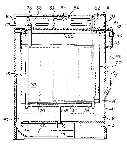
The basic multi-cell design consists of an open top
common electrolyte tank 10 having side walls 11, end
walls 12, a recessed bottom wall 13 and a cover 14.
Depending upon the size of the battery, a number of air
cathode assemblies 15 fit into the tank 10 and create
the individual cells.
As will be seen from Figs. ~, 3 and 4, each air
cathode assembly 15 includes a pair of spaced apart
cathodes 16 mounted in a support frame 17. For con-
struction, each cathode 16 may be assembled within an
individual frame as shown in Fig. 4 and the two frames
are then joined together to form the complete cathode
assembly. Surrounding the sides and bottom of the
cathode assembly are side fins 25 and a bottom fin 18.
These are designed to fit snuggly within the electrolyte
tank 10. The top portion 19 of the cathode assembly is
in the form of a pair of walls defining therebetween a
gap communicating with the air pocket~
Spacers 22 are positioned within the air pocket be-
tween the cathodes 16 and these are formed as two mating
parts as shown in Figs. 5, 6 and 71 each half consistiny
of vertical members 28 with projections 29 and horizontal
top and bottom members 30 with projections 31. Each half
is assembled with one cathode so that when two cathodes
and frames are joined to form the cathode assembly, the
projections 29 and 31 of each half contact each other
respectively, thereby leaving air gaps as shown in Fig.
9 3 ~76~
4~ At the same time, the solid portions formed between
the air gaps provided a light weight, rigid stiffener
between the cathodes.
Adjacent the cathodes 16 are a pair of air channels
20 extending from the top of the cathode assembly 15 and
flow connecting to the bottom of the air pocket between
the cathodes. This permits the drawing of fresh air into
the air pocket.
Also positioned adjacent the cathodes are a pair of
vertical spacer strips 26. Each of these spacer strips
includes a recessed groove 27. When the cathode assemb-
lies are juxtaposed in an electrolyte tank 10, the spacer
strips contact each other forming vertical barriers
between the active areas, iOe. the cathode/anode areas,
and the outside edges of the battery. The recesses 27
of a contacting pair of spacer strips together form a
slot into which a metal anode slides. The anodes are
limited in their movement downward by means of project-
ing abutments 24 mo~nted on frame 17.
The top of each air cathode assembly includes out-
ward projections 21 for sliding into a top support holder.
The top support frame can best be seen from Figs. 9,
10 and ll and comprises a main body portion 68 down from
which extend slideways 32 Eor receiving the top ends of
the air cathode assemblies. Stiffener bars 33 extend
upwardly from the support frame and these stiffener bars
may include gripping slots 73 for lifting the top holder
with the air cathode assemblies installed.
A series of slots 69 are also positioned in the body
portion 68 and these slots are positioned to receive the
anodes 35 between the air cathode assemblies. Each anode
includes a tab 36 which projects through the top of the
holder 68 to which electrical connections 67 are made.
The air cathode electrical connections can come up through
the air pockets in the cathode assemblies, or may be mold-
ed into the assembly itself to prevent contact with the
- 10 ~ t~6~72
electrolyte. The current carrier for the cathode can
be either a flexible wire 67 or a relatively solid
busbar. Preferably, a solid busbar is insert molded.
These cathode busbars then protrude in a pattern with
the anode tabs and the required connections are then
made by pushing a multi-socket type connector bar into
all protruding tabs, making all required connections in
one step.
The slots 69 in the cathode holder 68 through which
the anodes 35 pass are closed during operation of the
battery by sliding a slide plate 52 along the top of the
holder 68. This can best be seen from Figs. 13 and 14
and includes a main body portion 52 with a projecting
manifold 54 extending along the length thereof in a cen-
tral region. This manifold connects at the bottom ~o aseries of slots 55 and includes a single outlet 56 in
the top thereof. These slots 55 communicate with the
electrolyte chambers for each cell. During opera~ion,
any gases produced in the chemical reaction or used in
the process are forced to exit through the slots 55 into
the exhaust manifold 54.
Additional slots 53 are provided on each side of
manifold 54 and these slots are positioned to communi-
cate with the top ends of the air cathode assemblies
providin9 communciation with the air pocket of each
cathode assembly, through slots 71 in top holder 68.
Over the top of the tank 10 is the top cover 14 hav-
ing a top panel 57 with a series of slots 58 extending
therethrough and a central opening 5g. The cover 14
also includes outer side panels 60, end panels 7Q and
intermediate panels 62 forming a pair of long thin
chambers 63. Air inlet slots 61 are provided in side
walls 60 so that cool fresh air may be drawn in through
slots 61 and down through air intakes 50 into air chan-
nels 20. Warm air from the top of each air cathode airpocket may discharge upwardly through the slots 58 in
~;~7~37;~
the cover and exit gases from the electrolyte chambers
discharge through manifold 54, outlet 56 and opening 59
in the cover.
The tank 10 may have lifting handles 64 and the cover
14 may be provided with hooks 65 so that the cover may be
fixed to the tank by means of clips 66.
The electrolyte tank 10 itself also includes a number
of unique features including a liquid electrolyte manifold
43 with an inlet 44 for adding electrolyte to the system.
Extending downwardly from the manifold are a series of
tubes 42 which pass through the wall of the tank 10 in a
lower region inclined at an angle ~ of typically about 30.
Each tube 42 thereby communicates with an electrolyte
æone within the tank~ Thus, when activating the system
by filling it with elec~rolyte, the manifold 43 provides
a common point for adding the electrolyte from which the
individual cells are filled. During this ~illing period,
and throughout the operation of the battery, this side
manifold maintains a uniform electrolyte level in all
cells, by virtue of the common attachment for pressure
and level equalization. No common electrolyte path can
be allowed directly from cell to cell without involving
significant shunt current losses~ Therefore, relatively
long tubes are used between the manifold 43 and the elec-
trolyte tank 10, creating a long path from cell to cell,
hence minimizing shunt currentsO The point at which these
tubes connect to the tank 10 and the angle at which they
are mounted is also for a flush cleaning process at the
end of the battery operation.
Inside tank 10 are a series of T-tubes including a
cross tube 37 and an upwardly extending arm 39. As will
be seen from Fig. 8, the tubes 37 are positioned directly
beneath the anodes 35. The bottom end of each vertical
tube 39 communicates with an air manifold 40 having an
intake 41 and the cross tube 37 has a series of holes
38. These tubes are used to inject air or other yas
- 12 - ~ ~76972
into the electrolyte which results in many benefits such
as stirring, hydrogen gas dilution and heat removal. The
lifting action created by the rising gas in the electro-
lyte is used to circulate the electrolyte within each
individual cell. The vertical spacers 26 on adjoining
air cathode assemblies which contact to form baffles
are inherent to this process. It can be seen in Fig. 2
that the baffles 26 extend to just below the cross pieces
of the air injection tube 37. This ensures that all the
gas injected is captured between the baffles and forces
that part of the electrolyte to rise~ When the bubbles
reach the surface of the electrolyte, they escape and
are exhausted through the exhaust manifold 54, having
diluted the hydrogen gas to a safe level. The lifting
of the electrolyte between the baffles creates a spill-
over circulation down the outside of the baffles. This
electrolyte then reaches the bottom of the sump (in the
bottom of tank 10), where the velocity decreases sub-
stantially. At this point, much of the solid hydroxide
by-product, which tends to be in a granular form due to
the stirring action, drops to a stagnant area at the
bottom of the cell. The electrolyte that recirculates
through the cycle tends to be relatively free of solids,
although a certain amount of fines stay wi~hin the cir-
culating electrolyte throughout the battery opera~ion,
resulting in a whitish-coloured electrolyte. The removal
of the solids in this fashion prevents the build-up of
by-product on the electrodes, resulting in a much longer
battery life and much easier cleaning.
Beneath the recessed bottom floor 13 of tank 10 is
an area which holds a pair of manifolds. The first is
air manifold 40 which supplies the air to all of the air
injection tubes 37 and the second is a flushing manifold
47O Connected to manifold 47 are a series of tubes 46
which open into the bottom of the electrolyte reservoir
through holes 45 in bottom wall 13, one such hole 45
13 ~ ~27697~
being positioned beneath each electrolyte zone. During
operation of the battery, the manifold 47 and tubes 46
fill up with electrolyte and remain stagnant throughout
the bat~ery life. However, at the end of the battery
life, when the electrolyte is exhausted, a valve may be
opened on the end or bottom of the flushing manifold 47,
and the exhausted electrolyte and by~product is flushed
out. Again, it should be noted that tubes 47 preferably
provide long pathways between cells to prevent shunt
currents.
To aid in the cleaning process, once the flushing
manifold 47 has been opened, fresh water may be pumped
in through electrolyte manifold 43 and forced down each
side tube 42 to help flush out the solids. The angle
lS of the lower ends of the side tubes 42 is selected to
optimize the angle of impingement in order to be most
effective in the cleaning process. In order to ensure
that the electrodes are cleaned properly, fresh water
may also be back-flushed through the exhaust manifold
54. The slots 55 in the cover plate under the exhaust
manifold may be cut in the form of linear nozzles, whi~h
will spray the water across most of the electrode area
with a relatively high velocity in order to achieve
optimum cleaning. The battery cleaning may be carried
out without any disassembly of the battery, making this
device a simple t self-contained unit. No external pumps,
reservoirs or heat exchangers are required, wi~h the
exception of a small electrolyte make-up reservoir if
the battery is to be operated at relatively high current
densities for long periods of time, and a small pump to
feed the gas injection manifold if gas injection is used.