Note: Descriptions are shown in the official language in which they were submitted.
1~'770;~
SPECIFICATION
BACKGROUND OF THE INVENTION
1. Field of the Invention
The present invention is related to an antenna struc-
ture intended for use with a transmitter located at a great
depth below the earth's surface and which includes a metal
sleeve mounted on the outer surface of a drill collar which
forms part of a drill string used for petroleum exploration.
2. Description of the Prior Art
In drilling carried out in search of petroleum depos-
its, it is desirable to transmit to the site control cabin
at the earth's surface information supplied by sensors
located at the bottom of the drilling well which relates to
the pressure at the bottom of the well, the density of the
mud, temperature or other useful parameters. Thus, there
has been developed a system to transmit signals from a
transmitter housed in the drill collar of a drill pipe
string. For use as a transmitting antenna, one prior art
system utilizes a metal element formed by a portion of an
actual drill collar, insulated from the drill collar and
connected to it b~ a mechanical connection element made of
insulating material.
Thus, for example, in a thesis submitted to the Univer-
sity of Lille in 1969 by Mr. Clarisse, it was proposed to
divide the drill-pipe string, at the level at the last drill
~ ~77~)~7
collar, into two portions which are separated by a bridge
made of insulating material and ~etween which an alternating
electrical potential difference of specific frequency is
established. The lower part of the drill collar then forms
part of an antenna and the upper portion thereof is connect-
ed to the upper drill-pipes by means of threaded joints and
constitutes an axis which radiates and guides towaxd the
surface of the ground an electromagnetic wave capable of
remote transmission of signals supplied by telemetering
sensors located at the bottom of the drilling well~
A system of this type is also found in an article
entitled "Second-Generation MWD Tool" published on February
21, 1983 in the journal entitled Oil & Gas Journal, espe-
cially in the last paragraph on page 86 of this publication.
The serious disadvantage of this system is that in
order to make an insulating connection between the two metal
portions of the drill collar, it is necessary to use a hoop
or insulating bridge which reduces the mechanical strength
of the drill collar which, as is known, is subjected to
considerable torsional and shearing forces.
Another known antenna system includes a metal sleeve
made of cut sheet metal or of extremely thick mesh, which is
connected in an electrically insulating manner to the drill
collar of a drilling strin~ by means of suitable adhesive
such as epoxy resin~ Thus, the metal sleeve of the antenna
is mounted in an insulating manner around the drill collar
and is separated therefrom by a layer of bonding material,
such as epoxy resin. However, this metal sleeve is subject-
ed to considerable friction at the bottom of a drill hole,
particularly from contact with the wall of the well Thus,
0~7
it has been found that the sleeve must be made of the same
material as the drill collar and must have a sufficient
thickness which is close to 1 cm, and at a minimum of
approximately 8 mm. The problem with this construction is
that the metal sleeve of the antenna is so rigid that it
becomes delaminated at opposite axial ends thereof from the
drill collar due to strain which results from bending
vibrations the drill collar is subject to during drilling.
As such, the opposite axial ends of the metal sleeve tend tG
separate from the adhesive material which causes potentia'
infiltration of the drilling mud between the metal sleeve
and the drill collar and in addition causes a loss of
electrical insulation.
It is an object of the present invention to provide an
antenna structure which retains its resistance to abrasion
but yet remains flexible so that it can accommodate the
bending stress undergone by the drill collar to which it is
attached by a layer of insulating adhesive material.
It is an object of the present invention to provide an
antenna structure which includes a metal sleeve forming part
of the antenna wherein the opposite axial ends of the sleeve
are disposed on the drill collar in such a manner that
significant short circuiting of alternating current supplied
to the metal sleeve is avoided. To avoid this problem it
has been found that the opposite axial ends of the
cylindrical metal sleeve forming part of the antenna should
be spaced a sufficient distance in the axial direction from
the opposite axial ends of the insulating sheath disposed
between the cylindrical metal sleeve and the drill collar.
Thus,, when the cylindrical metal sleeve is mounted in a
~770'~7
recess in the outer surface of the drill collar, it has been
found that the insulating sheath should extend around 50 cm
beyond the opposite axial ends of a cylindrical metal sleeve
which may be from 2-6 meters long.
By providing an insulating sheath of sufficient length
beyond the opposite ends of the cylindrical metal sleeve, .
it is possible to minimize the problem of electrical current
leakage due to short circuiting through the drilling fluid
which circulates in the space between sides of the well and
the surface of the drill collar, the drilling fluid
characterized by an electrical resistance of generally
between 0.3 and 3 ohms/meter. However, since the insulating
sheath is necessarily constructed of an insulating material,
such as epoxy glue, the exposed portion of the insulating
sheath beyond the opposite a~ial ends of the cylindrical
metal sleeve is damaged by abrasion and rubbing against the
walls of the well due to its inferior strength and wear
resistance compared to the steel drill collar. on the other
hand, if the distance that the insulating sheath e~tends
beyond the opposite axial ends of the cylindrical metal
sleeve is reduced to several millimeters and if the
electrical resistance of the ground across rrom the
cylindrical metal sleeve is relatively high, for example
around 100 ohms/meter, nearly all of the current is
dissipated in a short circuit with the drill collar, with
the result that electromagnetic wave transmission is not
possible.
SUMMARY OF THE INVENTION
It is one of the objects of the present invention to
reduce the abrasion of the exposed surfaces of the adhesive
_ q _
~2~7'7~
covering on the drill collar which projects beyond the
opposite axial ends o~ the cylindrical metal sleeve forming
part of the antenna.
The above object is achieved by providing a plurality
of metal rings between each opposite axial end of the
cylindrical metal sleeve and a confronting opposite axial
end of the insulating sheath disposed between the
cylindrical metal sleeve and the drill collar, the rings
being electrically insulated from each other, from the
cylindrical metal sleeve and from the drill collar~ The
metal rings can be insulated from each other and from the
drill collar by embedding them in the insulating sheath.
The metal rings provide protection against abrasion of the
exposed insulating sheath yet do not affect the character-
istics of the insulating sheath with respect to its function
of preventing current leakage.
Another object of the present invention is to pro~ide
sufficient elasticity of the cylindrical metal sleeve such
that it follows the bending of the drill collar and prevents
it from separating from the insulating sheath securing it to
the drill collar. The cylindrical metal sleeve is made
elastic by providing a plurality of semi-annular circumfer-
entially extendlng slots therein. The slots can extend from
the radially inner surface of the cylindrical metal sleeve
to the radially outer surface thereof or the slots can
extend partly through the thickness of the cylindrical metal
sleeve. According to one aspect of the present invention,
the slots are arranged in a plurality of diametrically
opposed pairs with each o the pairs being spaced apart in
the axial direction along the length of the drill collar.
The pairs of slots can be arranged such that each pair of
0~
slots is offset angularly from each adjacent pair of slots.
Also, the slots can be arranged such that the ends of every
other pair of slots are aligned in the axial direction.
According to another aspect of the present invention, each
pair of slots can be angularly offset ~0 from an adjacent
pair of slots. Furthermore, the slots may have a width in
the axial direction of about one eighth ~1/8) the radial
thickness of the cylindrical metal sleeve, for example of
about 1 mm. Also, each pair of slots can be spaced from an
adjacent pair of slots by a distance in the axial directicn
equal to 40-60 times the width of the slots in the axial
direction, such as 30 to 50 mm.
According to another feature of the invention, there
can be provided 4~6 metal rings between each opposite axial
end of the cylindrical metal sleeve and the corresponding
axial end of the insulating sheath. The metal rings can
have a width in the axial direction of about 10 cm and can
be separated from each other by a distanre of about 3 mm.
The present invention provides an improved an-tenna
structure for transmitting signals from a transmitter at the
bottom of a drill well to the earth's surface by means of a
transmitter disposed in the drill collar and connected to
the cylindrical metal sleeve by means of conductors fitted
into insulated casings which extend through the drill collar
to the cylindrical metal sleeve. The improved antenna
structure is achieved by flexibility of the cylindrical
metal sleeve and by the prevention of separation of the
cylindrical metal sleeve from the insulating sheath, whereby
short circuits between the cylindrical metal sheath and the
drill collar are avoided.
7(~
Another object of the present inventlon is to provide a
method for manufacturing the improved antenna structure.
This method involves the use of spacer rings of insulating
material disposed at spaced intervals along the axial
direction between the cylindrical metal sleeve and the drill
collar. The spacer rings may be fitted in spaced-apart
circumferentially extending grooves in the drill collar and
insulating rings can be provided ~etween the axial ends of
adjacent pairs of the metal rings and between the axial ends
of the cylindrical metal sleeve and the adjacent metal
rings. The method of the present invention also provides a
removable casing fitted around the drill collar for
confining epoxy resin injected into the spaces ~etween the
metal rings and the drill collar as well as the spaces
formed by the circumferentially extending slots in the
cylindrical metal sleeve and the spaces between the
cylindrical metal sleeve and the drill collar.
~ RIEF DESCRIPTION OF THE DRAWINGS
The present invention will be described with reference
to the accompanying drawings, in which;
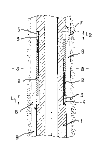
Fig. 1 is a vertical cross-section showing a prior art
drill collar in a drill hole, the drill collar including a
recess in which is mounted a cylindrical metal sleeve
forming part of an antenna and which is mounted to the drill
collar by means of an insulating glue;
Fig. 2 is a schematic vertical view of a drill collar
incorporating the antenna structure of the present inven
tion;
~,7~0V~7
Fig. 3 is a partial` perspective view of the cyllndrical
metal sleeve forming part of the antenna structuxe of the
present invention;
Fig. 4 is a cross-section of the cylindrical metal
sleeve shown in E'ig. 3;
Fig. 5 is a cross-section similar to that of Fig. 4 but
taken at a different point along the length of the
cylindrical metal sleeve;
Fig. 6 is a horizontal cross-sectional view of the
metal rings of the present invention, the metal rings beir.g
disposed between one axial end of the cylindrical metal
sleeve and a shoulder on the drill collar;
Fig. 7 is a partial cross-sectional view taken along
the axial length of the drill collar and showing a casing
according to the present invention used for confining
insulating glue around the antenna structure of the present
invention;
Fig. 8 is a horizontal cross-sectional view taken along
the axial length of the drill collar and showing a nozzle
attached to the casing of the present invention which is
used to create a vacuum or to inject glue in and around the
metal rings and cylindrical metal sleeve of the present
invention; and
Fig. 9 is a top view of a ring made of insulating
material, according to the present invention, which is used
to separate the cylindrical metal sleeve from the drill
collar and which includes a plurality of recesses extending
between opposite axial ends thereof for passage of glue
along the axial length of the drill collar when the
-- 8
~i~7~ 7
cylindrical metal sleeve and the metal rings are bonded to
the drill collar by the method of the present invention.
DETAILED DESCRIPTION OF THE PREFERRED EMBODIMENTS
The present invention is an improvement over the prior
art antenna structure shown in Fig. 1 in which a vertical
cross-section of a drill collar 1 includes a rigid metal
sleeve 2 which is electrically connected by insulated
conductors (not shown) to a transmitter device (not shown)
housed in the interior of the drill collar 1. The rigid
sleeve 2 is made of the same material as the drill collar 1
and is fastened in a recess 3 defined by opposite axial
shoulders 4, 5 in the drill collar 1. The sleeve 2 has an
inner diameter which is greater than the outer diameter o~
the drill collar 1 forming the recess 3. The sleeve 2 is
spaced from the outer surface of the drill collar defining
the recess 3 by a layer of insulating glue (not shown~, such
as an epoxy resin, which also fills the cylindrical cavity
of length L1 defined between the shoulder 4 of the recess 3
and the corresponding axial end surface of the sleeve 2 as
well as the cylindrical cavity of length L2 defined bètween
the shoulder 5 and the corresponding axial end surface of
the sleeve 2. The sleeve 2 forming part of the antenna is
thus completely insulated from the drill collar 1 and
separated from the terrain 8 defining the walls of the drill
well by an annular space 9 which is filled with drilling
fluid. Current leakage occurs between the sleeve 2 and the
drill collar 1 as shown by arrows 6 and 7. Thus, in order
to prevent short circuiting between the sleeve 2 and the
~ ~ 7 ~(~X~
drill collar 1 the leakage current must be reduced to a
minimum by maintaining the lengths L1 and L2 at a suf~icient
value, of, for example 50 cm. This prior art construction
does not provide sufficient flexibility of the sleeve 2 and
further the exposed portions of the insulating glue are
subject to abrasion which eventually leads to wear thereof
and eventual increase in leakage current. For instance, if
the lengths of the e~posed insulating material projecting
beyond the axial ends of the sleeve are reduced to several
millimeters and if the electrical resistance of the terrain
across from the sleeve is relatively high, _or example
around 100 ohms/meter nearly the entire current is dissipat-
ed by a short circuit with the drill collar resulting in
loss of the electromagnetic wave transmission.
The improved antenna structure according to the present
invention is shown in partial cross-section in Fig. 2. The
improved antenna structure of the present invention is
comprised of a drill collar 11 which extends in an axial
direction and which is adapted to support a transmitter (not
shown) therein, a cylindrical metal sleeve 12 for forming
part of an antenna for electromagnetic wave transmission,
the cylindrical metal sleeve being disposed around the drill
collar 11 and adapted to be connected electrically to the
transmitter, the cylindrical metal sleeve having a diameter
greater than the diameter of the drill collar and having an
axial length shorter than the axial length of the drill
collar, an insulating sheath disposed between the cylindri-
cal metal sleeve 12 and the drill collar 11, the insulating
sheath having an axial length longer than the axial length
of the cyl~ndrical metal sleeve, and a plurality of metal
-- 10 --
~LX~7C)~t~
rings 15, 16 disposed between opposite axial ends of the
cylindrical metal sleeve 12 and opposite axial ends of the
insulating sheath, the rings being electrically insulated
from each other, from the cylindrical metal sleeve and from
the drill collar. In order to provide greater flexibility
of the cylindrical metal sleeve 12, there is provided a
plurality of semi-annular circumferentially extending slots
in the cylindrical metal sleeve. The cylindrical metal
sleeve 12 provided with the circumferentially extending
slots will be described in greater detail with reference tc
Figs. 3-5.
As shown in Fig. 2, the drill collar ll includes a
cylindricai reinforcement 13 formed by an expanded diameter
portion of the drill collar 12, the cylindrical reinforce-
ment 13 having an upper axial end forming a iower shoulder
14 of the recess 3 in which the cylindrical metal sleeve 12
and the metal rings 15, 16 are received. The metal rings
are arranged such that a first plurality of metal rings lS
are disposed between one axial end of the cylindrical metal
sleeve and the shoulder 14 and a second plurality of metal
rings 16 are disposed between the other axial end of the
cylindrical metal sleeve 12 and an upper fastening collar 17
removably fitted to the drill collar 12 by suitable means,
such as screws. The insulating sheath bonding the cylindri-
cal metal sleeve 12 and the metal rings 15, 16 to the drill
collar 11 can comprise an epoxy resin which penetrates the
interstices separating the metal rings from each other and
from the cylindrical metal sleeve as well as the spaces
formed by the circumferentially extending slots in the
cylindrical metal sleeve. As such, separation of the resin
1~'70~7
joined to the drill dollar 11 is prevented and the metal
rings 15, 16 prevent separation a~d wear due to abrasion of
the exposed insulating resin which extends beyond the
opposite axial ends of the cylindrical metal sleeve. Thus,
the improved antenna structure of the present invention
prevents penetration of the drilling mud beneath the cylin-
drical metal sleeve or beneath the insulating sheath and
thereby prevents short circuiting between the cylindrical
metal sleeve and the drill collar.
The upper fastening collar 17 comprises a means on the
drill collar for axially sliding the plurality of metal
rings 1~, 16 and the cylindrical metal sleeve 12 onto the
drill collar. Thus, with the fastening collar 17 removed,
the lower metal rings 15 can be slid onto the drill collar
followed by the cylindrical metal sleeve 12 and the upper
metal rings 16. According to one embodiment of the present
invention, the number of first metal rings 15 can be 4 to 6
and the number of the second plurality of rings 16 can be 4
to 6. The metal rings lS, 16 can each have a width in the
axial direction of from 8 to 10 cm and the interstices
separating the rings from each other can be 1 to 3 mm.
The circumferentially extending slots will now be
described with reference to Figs. 3-5. As shown in Fig. 3,
th~ plurality of slots are arranged in a plurality of
diametricall~ opposed pairs with each of the pairs being
spaced apart in the axial direction. Also, each pair of
slots can be offset angularly from each adjacent pair of
slots and the ends of every other pair of slots can be
aligned in the axial direction. In particular, Fig. 3 shows
only one slot 18 of a pair of slots and the axial ends of
- 12 -
~77(3'~
the slot 18 are aligned in the axial direction with the ends
of another slot 20. A pair of slots 19, 19' are spaced
axially between the slots 18 and 20 and are angularl~ o~set
therefrom. The ends of the slots 19, 19' are aligned in the
axial direction with the ends of another pair of slots 21,
21'. As shown in Fig. Z, the circumferentially extending
slots form a plurality of semi-annular rings 23 connected
together by axially extending bridges 22, 22', as shown in
Figs. 4 and 5. Although the slots can extend from ~he
radially inner surface of the cylindrical metal sleeve to
the radially outer surface thereof, it is possible to
provide slots which extend only partly through the thickness
of the cylindrical metal sleeve. However, the distance that
the grooves extend in the circumferential direction is
limited to provide connecting bridges of sufficient length
in the circumferential direction to provide resistance to
shearing due to bending of the drill collar.
Fig. 4 is a cross-section taken in a plane perpendicu-
lar to the axial direction and passing through slot 18 and
as can be seen, a slot 18' is diametrically opposed to the
slot 18. Likewise, a bridge 22' is diametrically opposed to
.he bridge 22. Fig. 5 is a view similar to that shown in
Fig. 4, except that Fig. 5 is cross-section ~aken through
the pair of slots 21, 21'. As can be seen, a pair of
bridges 22, 22' separate the ends of the slots 21, 21'.
The following description relates to a preferred method
of mounting the metal rings 15, 16 and the cylindrical metal
sleeve 12 to the drill collar 11. In order to maintain the
rings 23 of the cylindrical metal sleeve 12 and the metal
rings 15, 16 concentric with the outer surface of the drill
- 13 -
~Z'~70;~7
collar 11, there are provided a plurality of spacer rings 24
of lnsulating material disposed at spaced intervals alony
the axial direction of the drill collar. The spacer rings
24 can be made of plastic material and can be fitted in
correspondingly shaped grooves in the drill collar. The
plastic spacer rings 24 allow the metal rings 15, 16 and the
cylindrical metal sleeve 12 to be spaced from the outer
surface of the drill collar by a distance as small as 1 mm.
The spacer rings 24 can be disposed at spaced intervals
along the axial direction and fitted between the cylindrical
metal sleeve and the drill collar at positions corresponding
to the circumferentially extending slots. In addition, the
spacer rings 24 can be disposed at positions corresponding
to adjacent axial ends of the metal rings 15, 16 as well as
positions corresponding to the opposite axiai en*s o~ the
cylindrical metal sleeve. As shown in Fig. 6, one of the
spacer rings 24 can be provided at a position corresponding
to the end of the metal ring facing the shoulder 14 and
likewise, one of the spacer rings 24 can be provided adja-
cent the axial end of the metal ring facing the fastening
collar 17. In addition to the spacer rings 24, insulating
rings 25 are provided between the axial end of the metal
ring 15 facing the shoulder 14 as well as between the axial
end of the metal ring 16 facing the fastening collar 17. As
shown in Fig: 6, washers 26 are provided between the adja-
cent axial ends of the metal rings 15, 16. The insulating
rings 25 can be made of any appropriate plastic material and
the washers 26 can be made from an elastomer, such as a
material known under the Trademark VITON. ~s shown in Fig.
9, the spacer rings 24 include a plurality of recesses 33
14 -
~7~0~7
therein which extend between opposite axial ends thereof for
passage of glue or other material forming the insulating
sheath when such material is injected between the
cylindrical metal sleeve 12 and the outer surface of the
drill collar and also allows the passage of such material
between the metal rings 15, 16 and the outer surface of the
drill collar 11.
A preferred method of bonding the rings 15 r 16 and the
cylindrical metal sleeve 12 with its rings 23 in an insulat-
ing manner in the recess 3 of the drill collar 11 will be
described as follows. After the metal rings 15, 16 and the
cylindrical metal sleeve 12 have been fitted in the recess 3
of the drill collar, the fastening collar 17 is secured to
the drill collar. Then, the metal rings 15, 16 and the
cylindrical metal sleeve 12 are covered with a casing
cylinder 27 with a space therebetween. The casing cylinder
27 can be made of sheet metal, such as zinc, and the casing
has a larger interior diameter than the outer diameter of
the cylindrical metal sleeve 12 and the metal rings lS, 16.
The sheet metal can be joined by soft soldering to form the
casing cylinder 27 or sheets of sheet metal can be attached
to two longitudinal clamps by suitable means, such as by
screwing the sheets to the clamps. The opposite axial ends
of the zinc casing cylinder 27 are each soldered to a ring
28 which forms a close fit with the outer surface of the
drill collar 11. The ring 28 is sealed to the outer surface
of the drill collar 11 by means of a second ring 29 and an
impermeable toric joint 30 which is fitted between a cam
surface on the ring 28 and a flat surface on the ring 29,
the ring 29 being tightened against the ring 28 with the
~77~
impermeable toric joint 30 therebetween by suitable means,
such as by screws 31, as shown in Fig. 7. The casing
cylinder 27 includes radially outwardly extending nozzles 32
which are used for creating a vacuum to aspirate epoY~y resin
from a suitable storage container such that the epoxy resin
is injected into all of the spaces between the various
assembled metal components. The nozzles 32 can be attached
to the cylindrical casing 27 by soldering or other suitable
means. The semi-circular shaped recesses 33 in the spacer
rings 24 allow the epoxy glue to spread along the drill
collar 11 and between the drill collar 11 and the
cylindrical metal sleeve as well as the metal rings 15, 16.
When the bonding step is completed, the fastening clamps are
loosened or the longitudinal soldered joint of the
cylindrical casing 27 is destroyed to thereby remove it from
the drill pipe 11. Subse~uently, the usual finishing
procedures such as polishing and balancing of the drill pipe
can be performed.
Although the present invention has been fully described
by way of example with reference to the accompanying draw-
ings, it is to be noted that various changes and modifica
tions will be apparent to those skilled in the art. There-
fore, unless otherwise such changes and modifications depart
from the scope of the present invention, they should be
construed as being included therein. For example, while
each pair of slots is shown as angularly offset by 90 from
an adjacent pair of slots, each pair of slots can be offset
with a different angular orientation from each adjacent pair
of slots. Also, the distance between the circumferentially
extending slots and the distance between the adjacent ends
- 16 -
~7~ 7
of the metal rings 15, 16 can be different from those values
specifically described in the specification.