Note: Descriptions are shown in the official language in which they were submitted.
7'7~1L6Y3
IRR~GATI~N APPLIANCE
SPECIFICATION
This a~plication relates to subject matter of
specidl concern to irrigation dppliances. More
particularly, it relates to improvements in connection
with apparatus within this yeneral field.
The most pertinent background is probably that
contained in the field of ora'l hygiene app'liances,
althouyh it has been recognized that many of the
improvements in appliances for that field also find
useful application in other areas such as the medical
cleaniny of wounds or cavities. Representative of the
prior art are U. S. patents 3,227,158, 3,425,410,
3,453,96Y, 3,467,083, Re 27,274, 4,094,311, 4,108,167,
4,302,186, 4,442,831, 4,452,238 and 4,534,340, as well
as some of the patents cited therein.
A11 of the foregoiny patents involve the
delivery of water in pulses with a deyree of control of
some characterlstic such as pressure. Usually,
pressure control was included in the base unit. As
~'~ will be observed, there have been some sugyestlons of
2~ placing it in the user's handpiece, so that the user
could achieve that contro'l without removing the
handpiece from his mouth when it was still del1vering
liquid. An alternatlve was to employ a second hand in
an inconverient manner whi'le at the same time collatiny
coordination.
Also include~ in the development within this
general Field was that of more and more convenient and
often portable units which enabled either or both of
~7~
easy transportation or attractive storage on sllch as
a bathroom counter top. One early approach was that
described in above patent No. Re. 27,274 which adopted
the inverted reservoir that, when placed downwardly,
served as a cover.
Thus, there have been many improvements in this
art at the same time that a few stones have been left
unturned. It is an object o~ an aspect of the present
invention to overturn a few more of those stones and
achieve further improvements in this art.
An object of an aspect of the present invention is
to provide a new and improved cover assembly which
better accommodates storage of everything when the unit
is not in use and yet which facilitates use during
operation.
An object of an aspect of the invention is to
provide better electrical operational facilities for the
kind of unit in ~uestion.
An object of an aspect of the invention is to afford
the user with a greater degree of convenience in control
of the pressure of delivered irrigating water or other
liquid.
In one aspect, the appliance includes a housing
having top and bottom walls joined by circumferential
side walls shaped to de~ine an inset, along a portion
thereof, that mates with a cover having a normally
horizontal wall from which projects a clrcumscribing
wall shaped to mate and has a similar inset. A
platform on the housing projects outwardly so that
there i5 a seat which enables an outlet device to be so
positioned that it i~ readily available to the user.
-2-
. ' ', ':
' - :..
. .-
'
.
lZ77~
Another aspect of the present invention involves
a new valve for use between such an inverted reservoir
in the form of a cover and its housing. That valve
features an I-shaped structure all of resilient
material. Structure formed in the housing may open the
valve, but cooperating structure in the cover lets the
valve prevent drainage when the lnverted cover ~s
removed.
Still another aspect of the new 1nvention
is the inclus10n of a sw~tcn arranyement so arranged in
this environment that it enables push-push sw~tchlng
while yet haviny hermet~c sealing, so as to protect the
interior. This involves the use of a well d~sposed in
the housiny and into which a barrel is inserted that
carries cooperative switch contacts. That barrel ls
tied to an operator assembly wh~ch enables push-push
operation.
One leading feature of that wh~ch is claimed,
however, per~a~ns to that wh~ch m~ght be called remote
2U control of pressure adjustment. The remote control is
a simple valve located 1n the hand-held device that
allows complete pressure control. Th1s 1nvolves a
system withln the base un~ wh~ch modulates flow from
~he reservo~r to the pump~n-g un~t and to the hand-held
dev1ce 1n response to the valve on that dev~ce, wh~le
at the same t~me modulatlng reverse flow back to the
reservo~r from the pump1ny un~t when the pressure or
flow rate of delivery is reduced by adjustment at the
hand-held un~t.
-3-
.. . .
': ' ' .' . .' ~ . :, . ,
, , '
.
" ' ' ' '
~2~7~6~
Another aspect of this invention is as follows:
An irrigation appliance comprising:
a housing having a top wall and a bottom wall
joined to said top wall by a circumferential side wall
shaped to define an inset along and lateral to one
portion thereof;
a cover having a normally horizontal wall from
which laterally projects a circumscribing wall shaped to
mate with said side wall when said cover is positioned
to overlie said housing in enveloping relationship, said
circumscribing wall also having a lateral inset that
mates with said inset of said side wall when said cover
iS 50 positioned;
inlet means defining an opening in said top wall;
outlet means defining an opening in said horizontal
wall and so located as to be aligned with said inlet
means when said cover is inverted to dispose said
circumscribing wall normally upstanding from said
~; hoxizontal wall;
means disposed within said housing for outletting a
liquid therefrom;
means disposed within said housing for pumping
liquid from said inlet means to said outletting means;
a device coupled for liquid flow from said
outletting means for delivery to a point of use;
: a platform fixed with respect to said housing and
projecting outwardly from beneath said inset in said
cover when said cover is so inverted;
and means in said platform de~ining a seat for
exposure of said device adjacent to said inset when said
: cover is so inverted.
The features of the present invention which are
: believed to be patentably are set forth with
particularity in the appended claims. The organization
~: 35
-3a-
.
' ' ' . ' '
:.,
~ 277:~6~
and manner of o~eration of one or more specific
embodiments of the invention, toyether with further
objects and advantages thereof, may best be understood
by reference to the followiny description taken in
connection with the accompanying drawings, in the
several figures of which like reference numerals
identify like e1ements, and in which:
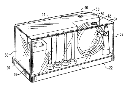
Figure 1 is a perspectlve view of an irriyation
appliance constructed in accordance with the present
invention;
Fiyure 2 is a similar v. ~ with different
components arranyed in different positions,
Figure 3 is a cross-sectional view taken along
the line 3-3 in Figure 2;
Figure 4 is a framentary cross-sectional view of
a component shown in Figure 3;
Figures 5 and 6 are cross-sectional views of a
sub-assembly included in Figures 1 and 2 and
respectively showing individually different components
2~ in different positions;
Fi~Jure 6A is a side elevational view of a
component shown in Figures S and 6;
Figure 7 is a cross-sectional view taken
longitudinally through a component shown ln Flgures 1
25 and 2;
Fiyures 8, 9, 10 and 11 are longitudinally-taken
cross-sectional views of a component included in Figure
3 but individually showing respective different
specific approaches; and
Figure 12 is a cross-sectional view of an
alternative to the component shown in Figure 7.
Shown in Fiyure 1 is an irrigating appliance
specifically originated for use in the field of oral
hygiene. It enables the user to direct a pulsating jet
-4-
,
~ 77~
~f water or other liquid for the purpose of tooth
cleaniny and ~um massage. However, such units also
have found important use in other areas at least in
personal care for such different implementations oF use
S as wound debridiment or the flushing of debris from a
cavity. The overall operation of this kind of
apparatus is well described in various ones of the
patents mentioned in the introduction to this
application, an~ those patents are incorporated herein
by reference for detai'led understanding of
constructional details which may be employed.
The unit depicted in Figure 1 includes a housing
2U secured atop a base 22 and within which housiny are
disposed certain operative components later to be
described. Housing 20 has'a top wall 24 and an upper
surface on base 22 serves as a bottom wall 26. Top
wall 24 and bottom wall 26 are joined by a
circumferential side wall 28 shaped to define an inset
30 formed a'long one portion thereof.
A cover 32 has a normally horizontal wall 34
from which laterally projects a circumscribing wall 36
shaped to mate with side wall 28 when cover 32 is
positioned to overlie housing 2U in envelopin~
relationship. Wall 32 also has an inset 38 that mates
with inset 30 when cover 32 is so positioned.
An inlet 4U is formed in top wall 24. An outlet
42 is formed to define an openiny throuyh horizontal
wall 34 and is so located as to be ali~ned with inlet
4U when cover 32 is inverted to dispose its
circumscribiny wall 36 normally upstandin~ from top
wall 24. As indicated, circumscrib~ny wall 36 is
shaped to mate with side wall 28 when cover 32 is
' '
~2~7~6~
positioned to overlie the housing in enveloping
relationship, with inset 38 mating with inset 30 when
cover 36 is so positioned.
Disposed within housing 20 is a pump 50 driven
through a motion converter 52 from an electric motor 54.
Broadly viewed, such a pumping assembly may take the
form shown in the aforementioned U.S. patent 4,302,186.
Alternatively, the overall pumping assembly may be
constructed with a different approach, such as the
solenoid pump shown in U.S. Patent 4,607,627, issued
August 26, 1986.
In any event, liquid contained within the reservoir
of cover 32, when disposed ln its exposed upright
position as shown in Figure 2, is suctioned through a
valve 58 which is displaced upwardly in the bottom of
cov~r 32 at outlet 40 and through input tubing 60 into
the pump body from which said liquid is delivered under
pressure through an outlet hose 62 that continues
outwardly of housing 20. Again speaking broadly, th.is
-~ 20 overall arrangement was described in more detail in U.S.
patent Re 27,274.
What in use normally would be the front or user's
side of the appliance features an upstanding pedestal 70
- located in thi~ case to one side and which contains a
switching mechanism operated by a push button 72.
~: Further inwardly, and first with respect to the housing
20, is formed a platform 74 along which are defined a
plurality oP wells to accept the seating of a
corresponding plurality of ~et tips 75. Jet tips 75 may
be as described in more detail in U.S. patent No.
4,337,040.
An indentation in housing 20, disposed inwardly
~rom platform 74, accepts a multi-turn coil of outlet
-6-
' ' ' ' ' "' ' ' ' :, :' .
,
' . :, ~ .
- :
~l27~
conduit 62 which leads to a handpiece 76 seatable for
storaye within another well formed in platform 74 or,
alternatively, miyht ~eat upon a peg upstandiny from
that platform.
As shown in Fiyure 1, when cover 32 i s
downturned so as to cover the entire unit, it embraces
both tips 75 and handpiece 76. On the other hand, when
cover 32 is inverted so dS to serve as a reservoir For
a liquid, inset 38 exposes handpiece 76 and an attached
jet tip 75 for yraspiny and use by the operator.
In this case, valve 58 preferably is constructed
as shown in Figure 4, although it alterndtively may
take a different form such as that shown in several of
the references previously mentioned. Here, valve ~8
is yenerally of an I-shape and is composed of a
resilient material. It is disposed within an opening
~U formed in horizontal wall 34. Its transverse upper
bar 81 at one end of a ley 82 seals opening 8U when it
is disposed downwardly by resilient bar 86~ A well ~3
defined in top wall 24 has a centrally located passage
84. A circular nub ~S projects upwardly within well 83
to a location at which it enyayes the bottom surface of
a lower transverse bar ~6.
Thus, when cover 32 is removed from the base,
valve 5~ moves downwardly into sealiny relationship
against horizontal wall 34. ~ut when cover 32 is
inverted and placed atop wall ~4 in order to serve as
the reservoir, nub ~5 urges valve 58 upwardly, allowing
flow of liquid from the resevoir through openiny ~ and
downwardly pas~ a circumferentially spaced series of
flutes ~7 project~ny from wall 34 and witn the liquid
then flowin~ throuyh the interstices between those
flutes on into ~assage ~4 throuyh additional flutes ~.
~77~6~
Defined within pedestal 70 is a well 9~.
Exposed throuyh the wall of well 90 are a pair of
electrical contacts 92 and 94 which are spaced apart
lonyitudinally of the well. A barrel 96 is slideably
disposed within well ~ and has one end portion 9~
projectin~ outwardly from well Y~. An elongated and
resilient electrically-conductive element 100 is
secured on the lower end portion of barrel 96 in
aliynment with contacts 92 and Y4. Element 100 is of a
contormation, as shown, to electrically bridge contacts
92 and 94 when barrel 96 is moved to a first position
upwardly as shown in Figure 6, yet to open that bridge
~hen ~arrel ~6 is moved to a second and lower position
as shown in Figure 5.
The switch assembly beiny described may also
include a second lonyitudinally-spaced pair of contacts
1~2 and 104, enabliny the switch to serve in a
single-throw, double-pole configuration whenever it may
be desired to separately switch the supply of power not
2U only to motor 54 ~ut also to other apparatus. The
latter miyht be a rnicroprocessing unit as may be
desirable when incorporating a different kind of pump
as for instance in the case of the aforementioned
solenoid pump.
An operator 110 is secured to the upper end
portion 9~ of barrel 96. A spring 112 is disposed with
respect to barrel 96 to urge the barrel to an upper
position but is yieldable in response to pressure
exerted on operator 110 i n order to move the barrel
into the second and lower position. A finger 114 is
pivotably connected at one end 116 by an inward-facing
lug 117 which. seats in a recess formed in the side Of
operator 110 in order to endble finyer 114 to swiny
0
l~-terally. A second spring 118 is disposed with
respect to operator 110 i n order to urge finyer 114 to
swiny in a first direction to the left as shown in
Figures 5 and 6.
Also defined in pedestal 7~ on an outwardly-
projectiny wall 11~ is a raceway generally indicated at
120 and includlny a first ramp 122 and a second ranlp
124, both together with the formation on wall 119 of a
notch 126 spaced above a directin~ nub 1~8. A pin 130
projects inwardly from the lower end of fin~er 114 into
raceway 120, enabliny travel of pin 13~ out of notch
126 into ramp 122 under urying of spring 118 upon the
application of pressure to operator 110 followed by
movement of barrel 96 outwardly of well 90 under ur~ing
1~ of spring 112. Subsequently, and upon renewed pressure
applied to operator 11~, pin 130 is caused to travel
along ramp 124 as a result of which, under the urging
of spring 11~, pin 130 is caused by the additional
rampiny presented by director 128 to return into notch
` 20 126.
Preferably, the opposite side of wall 119 (not
shown) carries a mirror image of reaceway 120, notch
126 and nub 12~. Finger 114 then is joined by a
bridye 132 (Fiyure 6A) to a counterpart finger 114'
having a luy 117' and a pin 13~'. A post 134 on bridye
; 132 seats in and holds spring 11~ in position. This
balanced arrangement improves stability of the
assembly, and bridge 132 holds fingers 114 and 114'
together, This permits lugs 117 and 117' as well as
pins 130 and 130' to be spruny apart and then snapped
into their respective recesses and raceways.
The upper edge of wall 119 tapers to a point at
136 to assist in spreading pins 130 and 130' during
~ Z7~
asse~bly. Also aiding stability, ears 138 project
inwardly from skirt 13~a of operator 110 to ride on
res~ective sides of wall 119.
It will thus be seen that a so-called push-push
switch has been formed. It is bistable, switching from
one mode to the other mode on each successive actuation
of operator 110. An important additional feature shown
in Fiyure 5 is the irlclusion of an hermetic seal 139
seated between barrel ~6 and the upper end portion of
well 90. Considering that use of the appliance as
specifically embodied is intended to be performed
within an environment which often includes at least a
hiyh deyree of humidity, if not the inadvertent
splashiny of liquid such as water on the unit itself, .
seal 139 assists in avoidiny moisture-related problems
in the performance of the switching mechanism.
Handle 76 is located at the outer end of
flexible hose 62 and includes a seat 140 receptive of
2~ the lower end of jet tip or nozzle assembly 7S. As
shown in Figure 7, seat 140 is defined within a cap 142
which may be snap fitted upon a nose 144 of a cylinder
146. ~n 0-riny 148, disposed within nose 144,
accomodates the very lower end of jet tip 75 in the
manner described in the aforementioned U. S. patent
4.302,186.
Within a bore 150 of cylinder 146 ls a plunger
15~ at the base of which is an 0-ring 154 and whlch is
uryed in an upward direction, as shown, by a spriny
156. ~efined at one side ot bore 150 is a channel 158
the lower end oF which may be variably opened in
correspondence w~t~l the vertical position of plunger
152. Channel 158 allows flow around plunger 152 and on
- 10-
. .
~27~7~6~
'nto the upper end o~ bore 150 t'or delivery by tip 75.
That is, hose 62 is coupled into the bottom of bore 15U
to enable li~uid flow through and around spring 156 and
into channel 15~.
Adjustiny lonyitudinal position within bore 1~U
of plun~er 1~2 is a tab 160 which projects over the
upper end of plunyer 152 and is secured throuyh an
U-riny 162 to a finger-operable knob 164. As will now
be evident, rotatlon of knob 164 about its own
lonyitudinal axis causes movement of plunger 152
relative to channel 158 in order to throttle the rate
of flow of liquid arriving by way of hose 6~ and
u'ltimately de'livered through a tip 7~.
Pum~ 50 is shown in all of fi~ures ~-11 in
presently preferred forms, although, as indicated
above, it may take other forms. In Fiyure 8, it
: includes a piston 170 moved by a connecting rod 172
:
driven as usual through converter ~2. Piston 170
slides within a cylinder 173 reciprocally in order to
develop alternat.e pressure and suction within a
'manifold 174. The outlet 176 from manifold 174 is
coupled into flexible hose 62. As such, piston 170 and
: its joinder to rod 172 preferably are constructed in
accordance with the teaching in U. S. patent No.
2'5 4,10~,167.
Passaye ~4 within the housing assembly of Figure
4 is coupled into a snout 18U whlch leads into an upper
cap 1~2 as part of a housing within which is defined a
yovernor 184. Cap 182 mates with a lower portion 1~6
~ 30 in this case integrally formed with and upstanding from
the main pump body and in communication with manifold
174. As shown; cap 1~2 has a t'lange 18~ which carries
a tapered surface 1~0 so formed as to enable a snap fit
of cap 1~ upon body 186.
~277~6~;)
Seated within body 186 and partially within cap
182 is an insert 19~ within which is de~ined a first
channel 1~ narrowed down at its upper end 196 in order
to seat a ball valve 1~ when the latter is uryed
upwardly by the development of pressure within manifold
174. Below valve 198 are ribs 200 which allow valve
1~ to be limited in movement while yet allowing liquid
from reservoir 3~ to be drawn into manifold 174 upon
the suction stroke of piston 170 and thereafter forced
1~ into hose ~2 during a subse4uent pressure stroke at
which time valve 198 is sealed at lY6~ Thus, valve 198
serves as a free-floating inlet check valve, otherwise
functioning in the same manner as that which is
described in several of the prior patents herein above
mentioned.
Another channel 204 leads from the inlet to the
outlet side throuyh insert 192 and is necked down at
its lower end, adjacent to manifold 174, so as to
define a seat for a ball valve 206 urged downwardly by
a spriny 20~. Ball valve 198 serves as a first
re~ulator that responds to pump suction for enabling
liquid flow from reservoir 34 at a rate determined in
response to adjustment of the ~hrottliny action within
remotely and physically-separated hand-held device 76,
in this case by means of mere finger-operable twisti.ng
: of knob 16~. At the same t~rne, ball valve 206 and its
associated ConlpOnents serve as a second regulator
responsive to pressure developed by piston 170 to
enable liquid flow back from manifold 174 into
reservoir 34 at a rate correspondinyly determined by
-: that same throttling adjustment accomplished within the
remote hand-piece. Thus, the two check valves are
reciprocally poled to pass liquid in opposiny
-12-
~ . :
~Z77~
~irections to and from the reservoir, but the action is
coordinated with throttling control at the remote
hand-piece.
Figures 9 through 11 illustrate alternatives
devised for accomplishiny the same results of governing
liquid flow in response to throttliny action. In
Fiyure Y, ba'll valve 2U6 uryed by spriny 20~ is locate~
within an internal bore 210. ~all valve 19~ of Fiyure
8 is in this case replaced by a truncated nose 220
uryed upwardly by a spring ~26. That latter
combination serves the purpose of ball valve 19~ as
explained with regard to that shown in Fiyure 8. When
the valve established at 220 is caused to move
downwardly by pump suction, the liquid flows from the
reservoir throuyh a space left, or flutiny provided in,
the lower end of the drum-shaped structure 228 of valve
220.
The alternative depicted in Figure 10 is similar
to that of Fiyure ~, in that valve 206 is loaded by a
s~riny ~8 a~ain within an internal bore with an upper
valve 220 serving as the inlet check valve. The
primary diff'erence here is that the liquid flows around
a pair of flanges 230 formed on bo~y 220, possibly
eliminatiny aliynment problems that miyht occur with
the arranyement of the version of Figure ~.
The different versions of Figures ~-10 have all
used ball-type check valves. As Figure 11 illustrates,
that is not a necessary limitation in terms of freedom
of desiyn. In this case9 ~isposed within cavity 204 is
only a sinyle spring 240 that downwardly urges a
multip'le-valve body 242 which seats around the entrance
to manifold 174 in order to serve, dlong with spriny
240, as tne reverse-flow reyulator. At the same time,
-13-
~ Z~7~
body 242 includes an internal passage 244 which opens
in response to suction produced by piston 170. Thus,
and as shown, body 242 becomes both the first regulator
and the second re~ulator, with res~ect to alternative
directions of li~uid flow to or from reservoir 34.
Internal openin~ 244 permits unidirectional flow as a
part of a second check valve, the second check valve
actually beiny formed by the upward movement, against
spriny 24~, of body 242 upon increase in pressure
1~ within manifold 174 in response to throttliny action by
adjustment of knob 164 in the remote hand-piece.
Figure 12 illustrates an alternative user-held
handle 76' which is similar to handle 76 as shown in
detai1 in Figure 7 but which presently is preferred .
because it dffords an additional feature. Handle 76'
again is located at the outer end of flexible hose 62
and includes a seat 260 receptive of the lower end of
jet tip or nozzle assembly 75O Seat 260 is defined
within d cap 262 snap fitted upon a nose 264 of a
~0 cylinder 266~ An 0-rin~ 268, disposed within 264,
dccommodates the lower end ~ortion of tip 75 as before.
Contained withln bore 27~, oriented laterally of
cylinder 266 and continuing across an inlet passageway
272 aliyned with an outle~ passageway 274, is a
2~ cylindrical valve 276. Valve 276 ls sealed within bore
270 by an ~-riny 278. A knob 2~0 is mounted on the
~ projecting outer end of valve 276. Uefined
: circumferentially in the exterior surface of valve 276
is a channel 2~2 the depth of which changes in a
direction around the circumference of valve 276. Valve
: 276 is uryed ou-twardly of cylinder 266 by a compression
spring 2~4. ~ seal 286 confines flow from channel 2~2
into pdssa~eway 274.
-14-
~:77~
In its normal outward position, channel 282 is
ali~ned between passages ~72 and ~7~, with the latter
being sealed to the exterior surface of valve ~76 by an
O-ring 286. In the position illustrated, rotation of
valve 276, by means of knob 280, chanyes the depth of
channel 282 presented for the flow of water from
passa~e 272 on upwardly to passaye ~74. On the other
hand, mere thumb or finger pressure by the user on the
outer end of knob 280 uryes valve 276 inwardly against
lU the force of s~rlng 2~4 thereby displacing channel 282
out of the flow passageway and completely shutting out
the flow of liquid. This enables the user to
immediately shut oft the delivery of water from the
nozzle with a simple pushing motion of, say, his thumb.
That allows the user to remove the nozzle from his
mouth and either direct it into a basin and/or reach
down with a diyit of either hand and turn off the
- appliance so as to stop operation alto~ether.
It will thus be seen that a number of
20 advantageous features have been incorporated into a new
appliance specifically designed for oral irrigation but
also readily adaptable for other types of irriyation in
connection with both personal and other use. At ~he
same time, different features have been revealed that
2~ lead to convenience of user operation. Also disclosed
have been a variety of different features believed to
be useful in and of themselves.
While particular embodiments of the tnvention
have been shown and described, it will be obvious to
those skilled in the art that changes and modifications
may be made without departiny from the invention in its
broader aspects. Therefore, the aim in the ap~ended
-15-
.' ' . ' ' ' ' '
~27~
laims is to cover all such chanyes and modifications
as fall within the true spirit and scope of that which
i s p a t e n t a b 1 e :
We cl aim: