Language selection

Search

Patent 1278165 Summary

Third-party information liability

Some of the information on this Web page has been provided by external sources. The Government of Canada is not responsible for the accuracy, reliability or currency of the information supplied by external sources. Users wishing to rely upon this information should consult directly with the source of the information. Content provided by external sources is not subject to official languages, privacy and accessibility requirements.

Claims and Abstract availability

Any discrepancies in the text and image of the Claims and Abstract are due to differing posting times. Text of the Claims and Abstract are posted:

  • At the time the application is open to public inspection;
  • At the time of issue of the patent (grant).
(12) Patent: (11) CA 1278165
(21) Application Number: 1278165
(54) English Title: WATER TOWER
(54) French Title: CHATEAU D'EAU
Status: Expired and beyond the Period of Reversal
Bibliographic Data
(51) International Patent Classification (IPC):
  • E04D 01/26 (2006.01)
  • E04H 12/30 (2006.01)
(72) Inventors :
  • RAIKAMO, MIKKO HEIKKI (Finland)
(73) Owners :
  • MIKKO HEIKKI RAIKAMO
(71) Applicants :
(74) Agent: ROBIC AGENCE PI S.E.C./ROBIC IP AGENCY LP
(74) Associate agent:
(45) Issued: 1990-12-27
(22) Filed Date: 1986-11-28
Availability of licence: N/A
Dedicated to the Public: N/A
(25) Language of filing: English

Patent Cooperation Treaty (PCT): No

(30) Application Priority Data:
Application No. Country/Territory Date
85 47 30 (Finland) 1985-11-29

Abstracts

English Abstract


ABSTRACT OF DISCLOSURE
A water tower consisting of a main body extending upward
from the ground, a water channel and a pumping means for
pumping water into the water channel, which acts as a water
storage of the tower. In known water towers, the main water
storage is placed at the top of the tower, at a height of
several tens of meters, which means that the costs of
construction of the tower and its groundwork are consider-
able and impose strict requirements on the structure of the
tower. These problems are solved by the invention in that
the tower is provided with a water reservoir placed at its
lower end under the ground surface or substantially close to
the ground surface, said reservoir constituting a safety
storage of water, and that the water channel of the tower is
of a substantially narrow sectional form through the whole
of its length.
Fig. 2


Claims

Note: Claims are shown in the official language in which they were submitted.

7
CLAIMS
1. Water tower consisting of a main body extending upward
from the ground, a water channel and a pumping means for
pumping water into the water channel acting as a water
storage of the tower, wherein the tower is provided with a
water reservoir placed at its lower end under the ground
surface or substantially close to the ground surface, said
reservoir constituting a safety storage of water, and that
the water channel of` the tower is of a substantially narrow
sectional form through the whole of its length.
2. Water tower according to claim 1, wherein the main body
and its water channel are located directly above the water
reservoir.

Description

Note: Descriptions are shown in the official language in which they were submitted.


I ~ ~t~ 5
WATER TOWER
BAC~GROUND OF THE INVENTION
The presen-t invention concerns a water tower consisting of
an erec-t main body, a water channel and a means for purnping
water in-to the channel, which acts as a water storage of -the
tower.
At present, to crea-te the required pressure in the water
distribu-tion network, a structure is employed in which a
reservoir constituting a safety storage of water is elevated
to a height of several tens of meters above the consumption
level. Such structures are often massive in appearance and
dominate the landscape of the area. A reservoir like this
may have a volume of e.g. a million litres, which means that
the water in it weighs a million kg. This imposes very
strict requirements on the s-tructure of the reservoir i-t-
self, its support and the groundwork. r~oreover, since the
reservoir is built at an elevated level, it is subject to
the effects of the weather, which means that insulation of
-the reservoir is a prob3em in cold countries, where the
water in the reservoir rnust be protected against freezing in
winter. In most cases, small electric pumps are used for
filling -the reservoir. The water pressure is created by the
height of the tower, and the large reservoir acts as a
safe-ty storage. It is estimated that a full reservoir of
~i~

~ater wilL last e.g. half a day if the consumption is
normal. During this time, the pressure in the ne-twork falls
by 0,5-1 bar, depending on the case (i.e. if the electric
pumps are inoperative).
The invention is based on the applica-tion to wa-ter tower
structures of the physical fact that the internal, i.e. hyd~
rostatic pressure of a fluid is only dependent on the cliffe-
rence of height between the point of measurement and the
free surface of the fluid, which in this case means the
difference of height between the consumption level and the
wa-ter surface in the tower. In other words, the pressure
does not depend on the amount of water in the reservoir, bu-t
only on the level of the water surface. It follows that the
same pressure can be created e.g. by using a pipe of a small
diameter, even just a few centimeters, in which the wa-ter is
raised -to the required level of height.
08JECT OE THE INVENTION
The following questions are of importance to the construc-
tors and users of a water distribution network:
a. Sufficient water pressure in the network.
b. Sufficient supply of water.
c. Cons-tant pressure.
d. Reliability of operation.

~78~
e. Cost of the structures, construction time, viability of
the sites 7 co~plexi-ty of the technology involved, ex-tend-
ability etc.
f. Appearance of the tower and its adap-tabili-ty -to -the
surrounding landscape.
These prob:lems are solved by the present invention as
follows:
a. A sufficient pressure is achieved by building a tower of
the same height as a conventional water tower, but of a
considerably "narrower and ligh-ter" structure.
b. A sufficient supply of water is ensured either by build-
ing a water storage in/on the ground or using a corres-
ponding solution.
c. The water level in -the narrow tower is kept at the
required height by pumping more water into the -tower from
a reservoir or other water supply placed in the ground,
at a rate corresponding to the rate of consumption. This
means that the pumping power is varied with the ra-te of
consumption. In this way the pressure is kept constant,
so that the tolerance of variation could be something
like +/- 0,01 bar. Thus, if the height of the tower were
e.g. 40 m , the pressure variation would be 0,25 %,
which, considering -the variations caused by other factors
in the network, is qui-te insignificant.
d. Reliability of operation is ensured by providing the
system with a water storage (reservoir or the like) of a
.
' ~ . . .
.' '
'' ' . ,

4 ~ ~ ~8 ~3~
sufficien-t volume, placed in the ground, and with a
separate reserve power system to supply the required
energy to the pumps in case of a failure.
e. The tower can be built almost on any kind of ground, the
structures are light, there is only li-t-tle need for
thermal insulation and the size of -the water s-torage can
be increased if consumption increases. Construc-tion time
is short.
f. The structures to be erected overground are of an
ordinary type, and the narrow tower will easily fit into
the surrounding landscape.
To achieve these objects, the invention is charac-terized in
that the tower is provided with a water reservoir placed at
its lower end either underground or substantially close to
the ground surface and acting as a safety storage of wa-ter,
and that the water channel of the tower is of a subs-tanti-
ally narrow sec-tional form through the whole of its length.
An advantageous embodiment of the inven-tion is charac-terized
in that the main body of the tower and its wa-ter channel are
placed directly above the water reservoir.
BRIEF DESCRIPTION OF THE DRAWINGS
In the following, the invention is described with reference
to the drawings attached, wherein:

5 ~ 81~
Fig. 1 is a diagram of a conventional water tower.
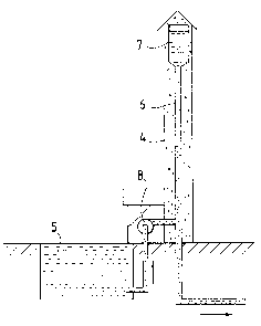
Fig. 2 is a diagram of a water -tower as provided by the
invention.
DETAILED DESCRIPTION OF T~IE PREFERRED EMBODIMENTS
Figure 1 shows a conventional wa-ter tower consisting of a
main body 1 and a wa-ter reservoir 2 placed at the top oE -the
tower. Inside the main body is a water channel 3, which is
considerably smaller in volume than the reservoir 2. A water
-tower like this is generally also provided with a pumping
means (not shown in the figure), used to replenish the
reservoir when necessary.
Figure 2 shows a water tower as provided by the invention,
in which the main body 4 is substantially of the same height
as the conventional water tower but narrow ("thin") in sec-
tional form through the whole of its length, because the
main storage of water, i.e. -the water reservoir 5, is placed
under -the ground surface or in its immediate vicinity. The
upper end of the water channel 6 in the embodiment shown in
fig. 2 is provided with a cavlty 7 sligh-tly wider in section
than the rest of the channel. However, this cavity 7 is
considerably smaller than the water r-eservoirs in conven-
tional wa-ter towers and need not necessarily be included in
the structure.
'

6 ~.~7~
"The upper part acting as a wa-ter storage of the tower" rnen-
tioned in 5he introduc-tory part of the c:l.aim refers to -the
whole of the water channel 6 as such or the combination of
the channel 6 and the small part 7. Naturally, the small
part 7 may also be narrower in sec-tion than the water
channel 6.
The water tower of the invention is provided wi-th a pumping
means 8, which is an essential part of the system and is
used for pumping water into the tower from the s-torage or
reservoir 5. The level of height of the water surface in the
water channel 6, 7 producing the pressure is maintained by
pumping more water into the channel 6, 7 from -the reservoir
5 on/in the ground. The pumping power is varied according to
the consumption in the distribution network in such manner
tha-t the surface of the water in the channel producing the
pressure remains at the desired level of height with a
sufficient accuracy.
It is obvious to a person skilled in the ar-t that the inven-
tion is not restricted to the examples of its embodimen-ts
discussed above, bu-t that it may instead be varied within
the scope of the following claims. Thus, for instance, the
water reservoir 5 need no-t be in the immediate neighbourhood
of the tower but may instead be located in a suitable place
in the terrain. Also, the reservoir may be placed under the
-tower, so that the main body and the water channel inside it
are directly above the reservoir. Further, it is possible to
use a lake, river etc. :in place of a reservoir 5.

Representative Drawing
A single figure which represents the drawing illustrating the invention.
Administrative Status

2024-08-01:As part of the Next Generation Patents (NGP) transition, the Canadian Patents Database (CPD) now contains a more detailed Event History, which replicates the Event Log of our new back-office solution.

Please note that "Inactive:" events refers to events no longer in use in our new back-office solution.

For a clearer understanding of the status of the application/patent presented on this page, the site Disclaimer , as well as the definitions for Patent , Event History , Maintenance Fee  and Payment History  should be consulted.

Event History

Description Date
Inactive: Reversal of expired status 2012-12-05
Time Limit for Reversal Expired 2007-12-27
Letter Sent 2006-12-27
Inactive: IPC from MCD 2006-03-11
Inactive: Late MF processed 2003-12-08
Grant by Issuance 1990-12-27

Abandonment History

There is no abandonment history.

Fee History

Fee Type Anniversary Year Due Date Paid Date
MF (category 1, 7th anniv.) - small 1997-12-29 1997-12-29
MF (category 1, 8th anniv.) - small 1998-12-29 1998-12-29
MF (category 1, 9th anniv.) - small 1999-12-29 1999-12-22
MF (category 1, 10th anniv.) - small 2000-12-27 2000-11-14
MF (category 1, 11th anniv.) - small 2001-12-27 2001-12-12
MF (category 1, 12th anniv.) - small 2002-12-27 2002-12-05
MF (category 1, 13th anniv.) - small 2003-12-29 2003-12-08
MF (category 1, 14th anniv.) - small 2004-12-27 2004-12-03
MF (category 1, 15th anniv.) - small 2005-12-28 2005-12-12
Owners on Record

Note: Records showing the ownership history in alphabetical order.

Current Owners on Record
MIKKO HEIKKI RAIKAMO
Past Owners on Record
None
Past Owners that do not appear in the "Owners on Record" listing will appear in other documentation within the application.
Documents

To view selected files, please enter reCAPTCHA code :


To view images, click a link in the Document Description column. To download the documents, select one or more checkboxes in the first column and then click the "Download Selected in PDF format (Zip Archive)" or the "Download Selected as Single PDF" button.

List of published and non-published patent-specific documents on the CPD .

If you have any difficulty accessing content, you can call the Client Service Centre at 1-866-997-1936 or send them an e-mail at CIPO Client Service Centre.


Document
Description 
Date
(yyyy-mm-dd) 
Number of pages   Size of Image (KB) 
Claims 1993-10-13 1 14
Abstract 1993-10-13 1 18
Drawings 1993-10-13 2 32
Descriptions 1993-10-13 6 151
Representative drawing 2001-12-20 1 6
Maintenance Fee Notice 2007-02-06 1 171
Fees 1998-12-28 1 32
Fees 1997-12-28 1 32
Fees 1996-12-23 1 38
Fees 1992-11-23 1 31
Fees 1995-11-14 1 38
Fees 1994-12-08 1 41
Fees 1993-11-04 1 32