Language selection

Search

Patent 1278237 Summary

Third-party information liability

Some of the information on this Web page has been provided by external sources. The Government of Canada is not responsible for the accuracy, reliability or currency of the information supplied by external sources. Users wishing to rely upon this information should consult directly with the source of the information. Content provided by external sources is not subject to official languages, privacy and accessibility requirements.

Claims and Abstract availability

Any discrepancies in the text and image of the Claims and Abstract are due to differing posting times. Text of the Claims and Abstract are posted:

  • At the time the application is open to public inspection;
  • At the time of issue of the patent (grant).
(12) Patent: (11) CA 1278237
(21) Application Number: 1278237
(54) English Title: INSULATION COVER OF STEAM TRAP
(54) French Title: REVETEMENT ISOLANT POUR DESHUMIDIFICATEUR DE VAPEUR
Status: Expired and beyond the Period of Reversal
Bibliographic Data
(51) International Patent Classification (IPC):
  • F16L 59/16 (2006.01)
  • F16L 59/05 (2006.01)
  • F16L 59/06 (2006.01)
  • F16T 1/38 (2006.01)
(72) Inventors :
  • KAMATA, SABUROU (Japan)
(73) Owners :
  • TLV CO. LTD.
(71) Applicants :
  • TLV CO. LTD. (Japan)
(74) Agent: NORTON ROSE FULBRIGHT CANADA LLP/S.E.N.C.R.L., S.R.L.
(74) Associate agent:
(45) Issued: 1990-12-27
(22) Filed Date: 1985-08-02
Availability of licence: N/A
Dedicated to the Public: N/A
(25) Language of filing: English

Patent Cooperation Treaty (PCT): No

(30) Application Priority Data:
Application No. Country/Territory Date
59-125661 (Japan) 1984-08-18

Abstracts

English Abstract


ABSTRACT OF THE DISCLOSURE
In a steam trap having an outer casing and pipe
connection portions extending outwardly therefrom, the
trap including an outer covering member extending over the
outer casing and in spaced relation thereto, the covering
member mechanically abutting against the pipe connection
portions, the improvement comprising: fusing the covering
member to the pipe connection portions whereby to positively
join the covering member to the pipe connection portions
and provide a sealed air- and water-proof joint therebetween
and accordingly a sealed space surrounding the steam trap.


Claims

Note: Claims are shown in the official language in which they were submitted.

The embodiments of the invention in which an exclusive
property or privilege is claimed are defined as follows:
1. In a steam trap having an outer casing and pipe
connection portions extending outwardly therefrom, said
trap including an outer covering member extending over
said outer casing and in spaced relation thereto, said
covering member mechanically abutting against said pipe
connection portions, the improvement comprising: fusing
said covering member to said pipe connection portions
whereby to positively join said covering member to said
pipe connection portions and provide a sealed air and
water-proof joint therebetween and accordingly a sealed
space surrounding said steam trap.
2. The improvement, as defined in claim 1, wherein
said fusing of said cover member is by welding to said
pipe connection portions.
3. The improvement, as defined in claim 1, wherein
said fusing of said cover member is by braising said pipe
connection portions.
4. The improvement, as defined in claim 1, wherein
said fusing of said cover member comprises two parts
which are butt-joined together by welding.
5. The improvement, as defined in claim 1, wherein
said fusing of said cover member comprises two parts
which are butt-joined together by braising
6. The improvement, as defined in claim 1, wherein
the spacing between said outer casing and said outer
covering member comprises insulating material.

7. The improvement, as defined in claim 6, wherein
said insulating material comprises ceramic fibre.

Description

Note: Descriptions are shown in the official language in which they were submitted.


~7~;~3~
The present invention relates to improvements in
steam traps, for example, ones which automatically discharge
condensate from steam systems. It more particularly relates
to the jointing construction between the casing of such traps
and the outer covering member therefor, which may comprise
an insulation cover. Such insulation covers have come into
being with the growing tendency to energy conservation,namely
to prevent the steam heat loss from steam traps due to
radiation.
An example of known steam trap is disclosed in the
Japanese Patent Gazette, showing Utility Model Sho 56-12480.
In this example, an outer covering member covers the entire
surface of the trap casing, providing a clearance for
insulation with the trap casing. In such instance, the covering
member only mechanically abuts against the piping connection
part of the trap casing.
A major drawback respectivé the example comprising
the prior art, is that it suffers poor insulation quality.
This is due to the covering member, which may comprise various
materials including ones which can be welded or braised,
mechanically abutting the trap casing, resulting in a gap at
the jointing~portion, i.e., intermediate the pipe connection
portions thereof and the covering member. Such permits flow-
in and out of air and intrusion of water into the aforementioned
clearance for insulation. The flow-in and out of air and
intrusion of water are expedited by expansion and contraction
of air or water in the clearance for insulation space, thus
causing a decreasing insulation effect due to heat dissipation.
It is therefore a prime aim of the present invention
to eliminate the gap between the trap casing and the edge of
the outer covering member.

~ ;~78~37
In one aspect of the present invention there is
provided in a steam trap having an outer casing and pipe
connection portions extending outwardly therefrom, the trap
i~cluding an outer covering member extending over the outer
casing and in spaced relation thereto, the covering member
mechanically abutting against the pipe connection portions,
the improvement comprising: fusing the covering member to the
pipe connection portions whereby to positively join the covering
member to the pipe connection portions and provide a sealed
air and water-proof joint therebetween and accordingly a sealed
space surrounding the steam trap.
For example, by welding or braising the pipe
connection portions to the outer covering member, the gap
between the casing and the edge of the outer covering member
is completely eliminated. Flow-in and out of air nor
intrusion of water no longer occurs. When sealing the gap,
the sealing material is required to be heat-resistant. Sealing
by welding or braising provides an ideal joint including in
terms of being heat-resistant.
The inven-tion is iilustrated by way of example in
the accompanying drawing wherein
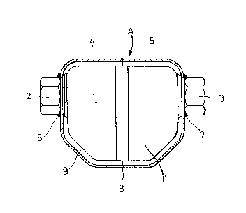
FIGURE 1 is a part sectional view taken through
a steam trap in accordance with the
present invention.
Referring to Figure 1, numeral 1 denotes the
conventional steam trap, the trap having a casing 1' and pipe
connections 2 and 3 extending therefrom. Numerals 4 and 5
denote respectively portions of an outer covering member A.
To facilitate assembly, outer covering member A is thus split
into two segments while arranged to cover the entire outer
surface of trap 1, except for the pipe connections 2 and 3.
Segments or portions 4 and 5 are fitted to trap 1 and welded
together along the central periphery denoted by numeral 8 and

7~ 37
further welded to trap casing 1' at steps comprising pipe
connections 2 and 3 denoted respectively by numerals 6 and 7.
A clearance space 9 is formed between the inner surface
of the cover A and the outer surface of the trap casing 1'.
Clearance space 9 may be filled with insulating material such as
ceramic fibre.
During operation of the steam trap in accordance with
the present invention, no intrusion of water occurs into the
clearance space 9, thus the insulating material therein will
not deteriorate, and the initial good insulation performance
remains in tact.
In the case of conventional prior art devices having
merely a clearance space between the outer covering member and
the trap casing, the radiation heat loss is equivalent to
condensation of 0.16 Kg per hour under the conditions of 5 kg/cm2G
trap inlet steam pressure and 10 mm/hr rain fall. Using the
insulated covering member according to the present invention
with the same steam trap, the heat loss is reduced to 0.11 Kg/hr.
This is simply one example to illustrate the improved efficiency
gained as a result of the present invention.
-- 4 --

Representative Drawing
A single figure which represents the drawing illustrating the invention.
Administrative Status

2024-08-01:As part of the Next Generation Patents (NGP) transition, the Canadian Patents Database (CPD) now contains a more detailed Event History, which replicates the Event Log of our new back-office solution.

Please note that "Inactive:" events refers to events no longer in use in our new back-office solution.

For a clearer understanding of the status of the application/patent presented on this page, the site Disclaimer , as well as the definitions for Patent , Event History , Maintenance Fee  and Payment History  should be consulted.

Event History

Description Date
Inactive: Reversal of expired status 2012-12-05
Time Limit for Reversal Expired 2007-12-27
Letter Sent 2006-12-27
Inactive: IPC from MCD 2006-03-11
Grant by Issuance 1990-12-27

Abandonment History

There is no abandonment history.

Fee History

Fee Type Anniversary Year Due Date Paid Date
MF (category 1, 7th anniv.) - standard 1997-12-29 1997-09-22
MF (category 1, 8th anniv.) - standard 1998-12-29 1998-12-07
MF (category 1, 9th anniv.) - standard 1999-12-27 1999-12-14
MF (category 1, 10th anniv.) - standard 2000-12-27 2000-12-08
MF (category 1, 11th anniv.) - standard 2001-12-27 2001-11-15
MF (category 1, 12th anniv.) - standard 2002-12-27 2002-11-19
MF (category 1, 13th anniv.) - standard 2003-12-29 2003-11-13
MF (category 1, 14th anniv.) - standard 2004-12-27 2004-10-01
MF (category 1, 15th anniv.) - standard 2005-12-27 2005-11-03
Owners on Record

Note: Records showing the ownership history in alphabetical order.

Current Owners on Record
TLV CO. LTD.
Past Owners on Record
SABUROU KAMATA
Past Owners that do not appear in the "Owners on Record" listing will appear in other documentation within the application.
Documents

To view selected files, please enter reCAPTCHA code :


To view images, click a link in the Document Description column. To download the documents, select one or more checkboxes in the first column and then click the "Download Selected in PDF format (Zip Archive)" or the "Download Selected as Single PDF" button.

List of published and non-published patent-specific documents on the CPD .

If you have any difficulty accessing content, you can call the Client Service Centre at 1-866-997-1936 or send them an e-mail at CIPO Client Service Centre.


Document
Description 
Date
(yyyy-mm-dd) 
Number of pages   Size of Image (KB) 
Cover Page 1993-10-14 1 11
Abstract 1993-10-14 1 15
Claims 1993-10-14 2 35
Drawings 1993-10-14 1 12
Descriptions 1993-10-14 3 102
Representative drawing 2001-07-11 1 7
Maintenance Fee Notice 2007-02-07 1 171
Fees 1995-09-25 1 56
Fees 1996-01-17 1 55
Fees 1993-03-08 1 50
Fees 1994-01-07 1 56
Fees 1992-07-30 1 50