Language selection

Search

Patent 1278413 Summary

Third-party information liability

Some of the information on this Web page has been provided by external sources. The Government of Canada is not responsible for the accuracy, reliability or currency of the information supplied by external sources. Users wishing to rely upon this information should consult directly with the source of the information. Content provided by external sources is not subject to official languages, privacy and accessibility requirements.

Claims and Abstract availability

Any discrepancies in the text and image of the Claims and Abstract are due to differing posting times. Text of the Claims and Abstract are posted:

  • At the time the application is open to public inspection;
  • At the time of issue of the patent (grant).
(12) Patent: (11) CA 1278413
(21) Application Number: 1278413
(54) English Title: PLATE WEB GIRDER
(54) French Title: POUTRE A AME PLEINE
Status: Expired and beyond the Period of Reversal
Bibliographic Data
(51) International Patent Classification (IPC):
  • F16S 1/10 (2006.01)
  • E04C 3/04 (2006.01)
  • E04C 3/07 (2006.01)
  • F16S 3/02 (2006.01)
(72) Inventors :
  • WARCZAK, FRANCISZEK (Australia)
(73) Owners :
  • FOLDED WEB BEAMS PTY. LIMITED
(71) Applicants :
  • FOLDED WEB BEAMS PTY. LIMITED (Australia)
(74) Agent: PIERRE LESPERANCELESPERANCE, PIERRE
(74) Associate agent:
(45) Issued: 1991-01-02
(22) Filed Date: 1987-02-27
Availability of licence: N/A
Dedicated to the Public: N/A
(25) Language of filing: English

Patent Cooperation Treaty (PCT): No

(30) Application Priority Data:
Application No. Country/Territory Date
54266/86 (Australia) 1986-03-04

Abstracts

English Abstract


ABSTRACT
A plate web girder comprising two flanges spaced by
a web of which the web comprises a metal sheet which is
"rippled", that is corrugated with small amplitude small
wave length corrugations or ripples and then corrugated
with large amplitude large wave length corrugations;
both the ripples and the corrugations extending in the
same direction from flange to flange.


Claims

Note: Claims are shown in the official language in which they were submitted.

CLAIMS
1. A girder comprising a corrugated web having
curvilinear corrugations, said web being fixedly
interposed between two flanges, wherein said web is
rippled, the ripples extending in a direction
substantially parallel to the direction of extension of
the corrugations and wherein the wave length "b" of the
ripples is in the range
3t ? b ? 6t
wherein "t" is the thickness of the web material and the
apmplitude "a" of the ripples is in the range
2t ? a ? 6t.
2. A girder according to claim 1 wherein the wave length
"L" of the corrugations is in the range
2A ? L ? 4A
where "A" is the amplitude of the corrugations.
3. A girder according to claim 1 fabricated from metal.
4. A girder according to claim 2 fabricated from metal.
-5-

Description

Note: Descriptions are shown in the official language in which they were submitted.


The present invention relates to plate web girders
which conventionally comprise a pair of elongate parallel
spaced apart flanges and an elongate web extending
therebetween.
It is well established that, when a bending moment is
imposed upon such plate web girders a large proportion of
the resultant bending stress is carriecl by the flanges and
that the web must be sufficiently stiff to hold the
flanges in spaced apart parallel relationship. That is to
say, the integrity of the girder depends inter alia, on
the web not buckling.
It is known to corrugate the web to increase its
stiffness to thereby provide a girder with an improved
increased strength to weight ratio. However, it has been
found that large corrugated webs are none the less prone
to buckling because due to the size of the corrugations,
the web acts locally like a plane web and as a result
local buckling may occur.
It is an object of the present invention to provide
an improved girder.
Accordingly, the present invention consists in a
girder co~prising a corrugated web as defined herein,
fixedly interposed between two flanges, characterised in
that said web is rippled, the ripples extending in a
direction substantially parallel to thè direction of
extension of the corrugations.
A preferred embodiment of the present invention will
now be described by way of example only, with reference
- 2 - ~

27~
to the accompanying drawings in which;
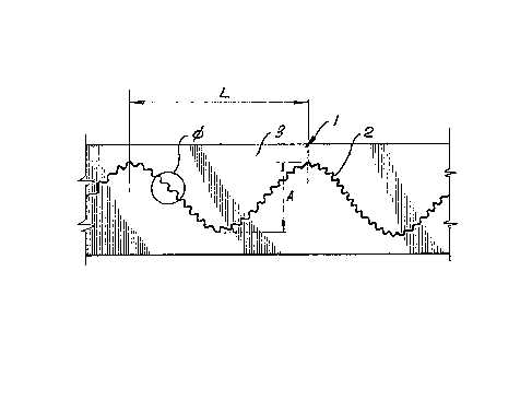
Figure 1 is a sectional plan view of a girder
according to the invention; and
Figure 2 is an enlarged sectional plan view showing
an encircled portion of the girder in figure 1.
Referring to the drawings, a girder 1 is shown which
comprises a corrugated web 2 fixedly interposed between
two flanges 3, only the lower one of which is shown for
clarity.
As is best shown in figure 2 the corrugated web 2 is
rippled.
Preferably, the thickness "t" of the web material
is in the range,
2t~ a~ 6t
where "a" is the amplitude of the ripples.
Additionally, the wave length "b" of the ripples
should be in the range
3t~ b ~6t
It has been found that a suitable way of producing
the rippled corrugated plate is to firstly pass a flat
plate through a press which stamps the ripples, a few at
a time, into the plate using a pair of dies fashioned in
the manner of a pair of intermeshing racks. The rippled
un-corrugated sheet is then passed betwèen a pair of
parallel rollers, each having axially extending, radially
projecting, intermeshing protruberances which effect the
bending of the rippled plate into its final corrugated
form. The rippled corrugated web is then welded to the
-- 3 --

~2S7~ 3
flanges in conventiorlal manner.
Preferably, the wave lenght "L" of the corrugations
is in the range,
~ A ~ L ~ 4A
where "A" is the amplitude of the corrugations.
In the preferred embodiment the corrugations are
defined by a serles of substantially semi-circular,
opposed curve portions. However, a corrugated web is
d~flned herein to comprise a web being corrugated in any
manner so as to have crests and troughs and is not
restricted to include only webs having sinusoidal
corrugations.
Similarly the ripples may have any of the
abovementioned forms.
For preference the gi~ders are fabricated rom steel
however, they may be fabricated from any metal or from
any suitable plastic.
-- 4

Representative Drawing
A single figure which represents the drawing illustrating the invention.
Administrative Status

2024-08-01:As part of the Next Generation Patents (NGP) transition, the Canadian Patents Database (CPD) now contains a more detailed Event History, which replicates the Event Log of our new back-office solution.

Please note that "Inactive:" events refers to events no longer in use in our new back-office solution.

For a clearer understanding of the status of the application/patent presented on this page, the site Disclaimer , as well as the definitions for Patent , Event History , Maintenance Fee  and Payment History  should be consulted.

Event History

Description Date
Inactive: IPC from MCD 2006-03-11
Inactive: Adhoc Request Documented 1994-01-02
Time Limit for Reversal Expired 1993-07-03
Letter Sent 1993-01-04
Grant by Issuance 1991-01-02

Abandonment History

There is no abandonment history.

Owners on Record

Note: Records showing the ownership history in alphabetical order.

Current Owners on Record
FOLDED WEB BEAMS PTY. LIMITED
Past Owners on Record
FRANCISZEK WARCZAK
Past Owners that do not appear in the "Owners on Record" listing will appear in other documentation within the application.
Documents

To view selected files, please enter reCAPTCHA code :


To view images, click a link in the Document Description column. To download the documents, select one or more checkboxes in the first column and then click the "Download Selected in PDF format (Zip Archive)" or the "Download Selected as Single PDF" button.

List of published and non-published patent-specific documents on the CPD .

If you have any difficulty accessing content, you can call the Client Service Centre at 1-866-997-1936 or send them an e-mail at CIPO Client Service Centre.


Document
Description 
Date
(yyyy-mm-dd) 
Number of pages   Size of Image (KB) 
Cover Page 1993-10-15 1 12
Abstract 1993-10-15 1 16
Claims 1993-10-15 1 20
Drawings 1993-10-15 1 21
Descriptions 1993-10-15 3 78
Representative drawing 2001-07-11 1 10