Language selection

Search

Patent 1278444 Summary

Third-party information liability

Some of the information on this Web page has been provided by external sources. The Government of Canada is not responsible for the accuracy, reliability or currency of the information supplied by external sources. Users wishing to rely upon this information should consult directly with the source of the information. Content provided by external sources is not subject to official languages, privacy and accessibility requirements.

Claims and Abstract availability

Any discrepancies in the text and image of the Claims and Abstract are due to differing posting times. Text of the Claims and Abstract are posted:

  • At the time the application is open to public inspection;
  • At the time of issue of the patent (grant).
(12) Patent: (11) CA 1278444
(21) Application Number: 1278444
(54) English Title: POLYGONAL TOOL FOR REMOVAL OF STRIPPED HEX HEAD FASTENERS
(54) French Title: OUTIL POLYGONE POUR L'EXTRACTION DE VIS A TETE HEXAGONALE AU FILETAGE ARRACHE
Status: Expired and beyond the Period of Reversal
Bibliographic Data
(51) International Patent Classification (IPC):
  • B25B 13/50 (2006.01)
(72) Inventors :
  • TAUBER, MICHAEL (United States of America)
(73) Owners :
  • SAFETY SOCKET SCREW CORPORATION
(71) Applicants :
  • SAFETY SOCKET SCREW CORPORATION (United States of America)
(74) Agent: BARRIGAR & MOSS
(74) Associate agent:
(45) Issued: 1991-01-02
(22) Filed Date: 1987-10-20
Availability of licence: N/A
Dedicated to the Public: N/A
(25) Language of filing: English

Patent Cooperation Treaty (PCT): No

(30) Application Priority Data: None

Abstracts

English Abstract


ABSTRACT
A tool for removing threaded fasteners such as
screws and/or bolts having hexagonal recessed sockets formed
in their heads, with the tool including an elongated broach
polygonal in cross section, with a sleeve having a like
cross sectional configuration slideably mounted thereon.
The sleeve is provided at one end with a protruding insert
head that is capable of being projected into countersunk
bores so as to have facial contact with a countersunk hex
head of a fastener, while the opposite end of the sleeve may
be countersunk so as to provide a receptacle for receiving
the protruding or exposed hex head of the fastener to be
removed.


Claims

Note: Claims are shown in the official language in which they were submitted.

The embodiments of the invention in which an exclusive
property or privilege is claimed are defined as follows:
1. In combination a tool for rotatably removing
fixed fasteners having heads that provide a normally
straight sided tool receiving socket that has become
stripped and is non-receptive to a normally straight sided
removal tool, including; a) an elongated broach polygonal in
cross section and having an outer dimension slightly larger
than the socket of the fixed fastener, so as to have its
either end forcefully projected therein, b) a sleeve having
a diameter greater than said broach, and a center bore of a
configuration corresponding to that of said broach, so as to
be slideable and reversible upon, yet non-rotatable about
said broach, c) a projection on one end of said sleeve
having an outer diameter of a size less than said sleeve and
greater than said broach and having a coaxially aligned
center bore of a configuration corresponding to that of said
broach so as to be projected longitudinally from one end of
said sleeve for placement in juxtaposition to a countersunk
flat surface of a recessed head of a fastener so as to align
said broach with the socket in the head while being
forcefully projected therein so that said fixed fastener may
be removed by rotation of the tool, and d) a recessed
receptacle formed in the opposite end of said sleeve about
said center bore thereof for receiving a raised exposed head
of a fastener so as to align said broach with the socket in
the head while being forcefully projected therein so that
said fixed fastener may be removed by the rotation of the
tool.
-5-

Description

Note: Descriptions are shown in the official language in which they were submitted.


~278~
SPECIFICATION
This invention relates to a tool utilized to
assist in the removal of hex headed fasteners when the
recessed hex configurated socket has become stripped or the
internal angles thereof have been disintegrated so that a
normal tool is incapable of insertion and engagement during
the attempt to remove the same.
The tool of this invention includes an elongated
rod-like broach formed polygonal in cross section and of a
diameter slightly larger then the recessed hex socket of the
fastener head. The broach is adapted to be forcefully
projected into binding contact with the disfigured recessed
hex socket of the fastener.
The tool in addition to the broach provides a like
configurated sleeve that is slideably ~ounted on the broach
so as to be freely moved longitudinally thereof. This
sleeve may be provided at one end with a projecting insert
head that is circular in cross section, the diameter of
which is generally equal to the diameter of the circu~ar hex
head of the fastener to be removed. The opposite end of the
sleeve may be recessed so as to provide a circular
receptacle for the head of the fastener to be removed.
In utilizing the tool of this invention it is
vital that the broach before its forcible insertion into the
recessed hex socket of the fastener head be in longitudinal
alignment with the shank of the fastener. To assure this
alignment the sleeve is slideably moved along the broach so
that it may, either receive in its receptacle end the
recessed hex head of the fastener, or into the alternative,
in the case of a countersunk astener be projected into the
countersunk bore for flat facial abutment with the exposed
complimentary flat surface of the hex head of the

12~
fastener. In either of these engagements the sleeve will
function to position and maintain the broach in proper
longitudinal alignment during the period of its forceful
insertion into the stripped hex socket of the head of the
fastener.
It also should be noted that once the broach has
operatively been placed in fixed engagement with the hex
socket the sleeve by reason of its hexagonal cross section
is adapted to be readily gripped by an associate tool such
as a wrench for imparting rotation to the fastener through
the broach.
Other ob~ects of the invention will be made
apparent by the following detailed description of the tool
of this invention.
ON THE DRAWINGS
The invention will be best understood by reference
to the accompanying drawings showing the preferred form of
construction and mode of operation by which the objects of
this invention are achieved and in which;
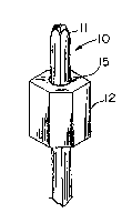
~ig. 1 is a perspective view of the tool assembly
of this invention,
Fig. 2 is a side elevational detailed sectional
view of the sleeve of the tool,
Fig~ 3 is a perspective view of the elongated
broach of the tool,
Fig. 4 is a fragmentary partially sectional
detailed view of the tool in use on a countersunk fastener,
and
Fig. 5 is a fragmentary partially sectioned
detailed view of the tool as used on a exposed fastener.
As illustrated in Fig~ 1 the tool 10 of this
-2-

~;~7~
invention includes an elongated polygonal broach 11 and a
polygonal sleeve 12. The sleeve 12 is provided with a
center bore 13, the cross section of which resembles the
polygonal cross section of the broach 11 so that such sleeve
12 is freely slideable longitudinally on the broach 11.
As viewed in Fig. 2 the sleeve 12 has one end 14
: recessed as at 15, with the recess 15 having open
communication with the internal bore 13 of the sleeve 12.
It should be noted that the end recess 15 of the sleeve 12
is normally circ~lar in cross section and of a diameter
greater than that of the center bore 13.
The opposite end 16 of sleeve 12 is formed to
provide a longitudinally circular projection forming an
insert head 170 It should again be noted that the
counterbore 13 extends throughout the length of the insert
end 17 by reason of the fact that the diameter of the insert
17 is greater than that of the bore 13.
When the tool is used to extract a countersunk hex
head fastener 18 as illustrated in Fig. 4 the sleeve 12 is
positioned such that its insert end 17 projects into the
counter bore 19 and sits in facial contact upon the exposed
flat head 20 of the fastener 18. In this position the
broach 11 will be in substantial longitudinal alignment with
the shank 21 as well as the hex socket 22 formed in the head
20 of the fastener 18~ As the sleeve 12 holds the broach in
such alignment, the broach can be forcibly inserted into the
stripped hex socket formed in the flat head 20 of the
fastener 18. This forceul insertion of the broach 11 may
be accomplished by striking the free standing exposed
opposite end with a tool such as a hammer and the like.
When the broach has been forcibly inserted in the hex socket
22 a suitable tool such as an adjustable wrench may be
clamped upon the sleeve 12 for rotating it, as well as the
--3--

~7~
broach, in an unthreading rotational direction which will be
imparted to the fastener 18 so as to effect removal of the
same.
In Fig. 5 the tool of this invention is shown in
application upon the exposed head 23 of a hex head fastener
24. In this circumstance the opposite end of the sleeve 12
is aligned with ~he fastener 24 so that the head 23 of the
fastener is received within the recess 15 formed in the end
14 of the sleeve 12. In such a position the purpose,
function and operation of the cooperating broach 11 and
sleeve 12 are similar to ~hat previously described.
From the foregoing it is apparent that I have
provided a efficient tool for effecting removal of exposed
or coun~ersunk stripped hex head fasteners. The tool may be
made in sizes to correspond to the commercially available
hex head asteners such that the broach 11 will always
possess a configurated diameter slightly larger than the
recessed socket of the fastener's head.
While I have illustrated and described the
preferred form of construction and method for carrying out
my invention, this is capable o~ variations and
modifications without departing from the spirit of the
invention. I therefore, do not wish to be limited to the
specific details as set forth but desire to avail myself of
such obvious variations and modifications as come within the
scope of the appended claims.

Representative Drawing
A single figure which represents the drawing illustrating the invention.
Administrative Status

2024-08-01:As part of the Next Generation Patents (NGP) transition, the Canadian Patents Database (CPD) now contains a more detailed Event History, which replicates the Event Log of our new back-office solution.

Please note that "Inactive:" events refers to events no longer in use in our new back-office solution.

For a clearer understanding of the status of the application/patent presented on this page, the site Disclaimer , as well as the definitions for Patent , Event History , Maintenance Fee  and Payment History  should be consulted.

Event History

Description Date
Letter Sent 1999-12-15
Time Limit for Reversal Expired 1999-01-04
Letter Sent 1998-01-02
Grant by Issuance 1991-01-02

Abandonment History

There is no abandonment history.

Owners on Record

Note: Records showing the ownership history in alphabetical order.

Current Owners on Record
SAFETY SOCKET SCREW CORPORATION
Past Owners on Record
MICHAEL TAUBER
Past Owners that do not appear in the "Owners on Record" listing will appear in other documentation within the application.
Documents

To view selected files, please enter reCAPTCHA code :


To view images, click a link in the Document Description column. To download the documents, select one or more checkboxes in the first column and then click the "Download Selected in PDF format (Zip Archive)" or the "Download Selected as Single PDF" button.

List of published and non-published patent-specific documents on the CPD .

If you have any difficulty accessing content, you can call the Client Service Centre at 1-866-997-1936 or send them an e-mail at CIPO Client Service Centre.


Document
Description 
Date
(yyyy-mm-dd) 
Number of pages   Size of Image (KB) 
Claims 1993-10-15 1 41
Abstract 1993-10-15 1 17
Cover Page 1993-10-15 1 13
Drawings 1993-10-15 1 31
Descriptions 1993-10-15 4 148
Maintenance Fee Notice 1998-02-10 1 179
Fees 1999-12-06 1 48
Correspondence 1999-12-15 1 20
Fees 1997-01-02 1 33
Correspondence 1996-01-03 1 33
Fees 1995-12-15 1 29
Fees 1994-12-20 1 25
Fees 1993-11-18 1 25
Fees 1992-11-20 1 19