Note: Descriptions are shown in the official language in which they were submitted.
78G~3
CIRCULAR WARP KNIT COMPOSITE CORD
Field of the Invention
This invention relates generally to
circular warp knit composite cords or yarns, and
more particularly to a circular warp knit composite
cord including a circular warp knit tube formed by a
plurality of circumferentially spaced wales of base
yarn needle loops, and inlaid yarns interlaced in
selected ones of the wales of base yarn needle loops
and extending therealong to control longitudinal
lo stretchability and other physical characteristics of
the circular warp knit tube. If desired,
longitudinally extending core yarns or elements may
be provided in the center of the circular warp knit
tube.
Background of the Invention
It is generally known to inlay or
interlace yarns in selected wales of various types
of flat warp knit fabrics. Such inlaid yarns have
been incorporated in flat warp knit fabrics for
ornamental purposes, to provide stiffness, and to
provide other charactexistics to the fabric. It is
also known to form a circular warp knit cord or yarn
on a small diameter circular knitting machine by
forming wales of needle loops of base yarns
circumferentially spaced around a circular warp knit
tube, and with or without a core. Such a circular
warp knit cord is d.isclosed in U.S. Patent No.
~7~
--2--
~ 3,830 in whic~ the circular warp knit tube
surrounds a centra~ly extending core. ~owever, the
circular warp knit tube of this patent does not
include inlaid yarns interlaced in selected ones of
the wales o~ the base yarn needle loops 50 that th~
longitudinal stretchability of the circular Warp
knit tube is not stabilized. Therefore, the cord of
thiS patent is not suitable for use in certain
operations, such as knitting, wea~ing, w~apping or
the like, or for use in oth~r instances where
characterlstics such as longitudinal stretchabillty,
strength, stiffness, conductivity, bulk and
filtration properties must be imparted to the warp
k~lt cord.
summarv of the Invention
With the foregoing in mind, it is an
object of the present in~ention to provide a
circular warp knit composite cord, and wherein the
circular warp knit composite cord includes a
circular warp knit tube having a plurality of wales
of base yarn needle loops circumferentially spaced
around the tube with the base yarns forming the
wales of needle loops also forming laps extending
between and interconnecting the circumferentially
spaced wales Of base yarn needle loops, and inlaid
yarns interlaced in selected ones of the wales of
base yarn needle loops and extending longitudinally
therealong to control longitudinal stretchability of
the circular warp knit tube. The inlaid yarns
interlaced in the wales of the clrcular warp knit
tube also permit the imparting of certain other
characteristics to the composite cord which are not
obtainable if the inlaid yarns are not present. For
example, other physical characteristics of the cord
can be varied, depending upon the type of inlay
yarns used, such as tensile strength, stability,
bulk conductive properties and filtration and
~:78~
3--
osmotic properties~ If desired, a core yarn or
element may extend along the center of the circular
warp knit tube to provide additional characteris~ics
to the warp knit composite cord.
The circular warp knit composite cord of
the present invention provides a th~ee-dimensional
structure which retains its three-dimensional
chara~teristics after being knit or woven into
fabric form or after having been braided, served,
lo twisted, wound or the like. The physical properties
of the circular warp knit composite cord of thP
presen~ invention are determined by the typQs of
base yarns, inlaid yarns, and core yarns used, the
stitch size, the number of needles in the cylinder,
and the number, type and placement of the inlaid
yarns interlaced in the wales of the base yarn
needle loops. The types of yarns used in the
circular warp knit composite cord of the present
invention are selected to provide the desired
physical characteristics to the composite cord.
The circular warp knit composite yarn of
the present invention is knit on a circular warp
knitting machine equipped most frequently with a
relatively small needle cylinder containing from two
to twelve circularly arranged and circumferentially
spaced-apart needles. Certain end-products,
however, require larger needle cylinders containing
up to sixty or more needles. The needles are
supported for simultaneous longitudinal up and down
movement between an upper clearing or shed le~el and
a lower stitch loop forming or drawing level. The
circular warp knit composite cord is formed by
feeding a base yarn to each of the needles each time
the needles are moved to the raised clearing level
so that base yarn needle loops are formed when the
needles are moved to the lower stitch loop forming
level.
7~ 3
--4--
The base yarns which form ~eedle loops on
selected needles in each course are
~ircumferentially shifted to form needle loops on
other needl~s in the next course and to form laps
extending between and interconnecting the
clrcumferentially spaced wales ~f base yarn needle
loops. While the base yarns are being fed to the
vertically reciprocating ne~dles ~o form sUCCessive
courses, inlay yarns are guided to opposite
sides of at least selected ones of the needles as
they move between the clearing level and the stitch
loop forming level to thereby interlace the inlay
yarns in selected ones of the wales of the base yarn
needle loops.
The inlaid yarns of the present circular
warp knit composite cord can include various types
of yarn, depending upon the type of physical
characteristics to be imparted to the circular warp
knit composite cord. For example, glass, ceramic,
~Teflon," carbon, "Kevlar, n fiber optic, or
electrically conductive metal yarns may ~e utilized.
Brief Description of the Drawings
Other objects and advantages will appear
as the description proceeds when taken in connection
with the accompanying drawings, in which --
Figure 1 is a greatly enlarged and
somewhat schematic view showing the loop structure
of the circular warp knit composite cord of the
present invention:
Figure 2 is a view similar to Figure 1 but
further illustrating a core element extending along
the central portion of the composite cord;
Figure 3 is a fragmentary isometric view
of a portion of a circular warp knitting machine of
the type on which the circular warp knit composite
cord of the present invention is knit,
--5--
Figure 4 is an enlarged fragmentary
isometric view of the upper end por~ion of the
needle cylinder and the adjacent yarn guide
elements, illustrating the needles in the lowered
5 stitch loop forming level; and
Figures 5-7 are isometric views
illustrating the manner in which the base and inlaid
yarns are guided to the needles as they are raised
and lowered in the sequence of successive course
formations.
~escription of the Preferred Embodiment
The circular ~arp knit co~,posite cords
illustrated in Figures l and 2 are knit on a
circular warp knitting machine of the type
illustrated in Figures 3-7, including four
circularly arranged and circumferentially
spaced-apart latch needles supported for
simultaneous longitudinal movement, to be presently
described. However, it is to be understood that the
present circular warp knit composite cord may also
be knit on a circular warp knitting machine of the
type illustrated, including a greater or lesser
number of needles.
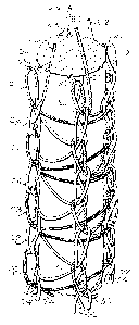
As illustrated in Figure 1, the present
rircular warp knit composite cord includes a
circular warp knit tube having four wales, indicated
at W-l through w-4, of base or body yarn needle
loops circum~erentially spaced around the tube. The
base yarn needle loops form successive courses
illustrated at C-l throuyh C-7. Separate and
individual base yarns, indicated at B-l through B-4,
each form base yarn needle loops in corresponding
wales W-l through W-4 of course C-l and form
circular and diagonally extending laps extending
between and interconnecting the circumferentially
spaced wales of the course C-l with opposite needle
loops positioned in the opposite wales in the next
33
--6----
successive cours~ C-2. Shading has been added to
the base yarns in Figures 1 and 2 to help
disting~lish one base yarn fl-om the other.
Corresponding inlaid yarns, indicated at I-l throuyh
I-4 are illustrated as beinq interlaced with the
base yaxn needle loops in corresponding wales W-1
through W-4.
The inlaid yarns I-l through I-4 extend in
a generally zigzag path along the corresponding
wales W-1 through W-4 and control the longit~dinal
stretchability of the circular warp knit tube. The
inlaid yarns I-l through I-4 can also be used to
impart other types of physical characteristics to
the composite cord. Laps of the base yarns extend
from certain needle loops in one course to opposite
needle loops in the next successive course. The
laps are illustrated as following a circular path in
Figure 1 in order to more clearly illustrate the
loop configuration. In actual practice, the wales
W-l through W-4 of base yarn needle loops are drawn
close together and the laps extend in substantially
a straightline path from a needle loop in one wale
of a given course to an opposite needle loop in the
next successive course of the circular warp knit
tube.
The circular warp knit composite cord of
Figure 2 includes the same type of circular warp
knit tube illustrated in Figure 1 and further
includes a core yarn or element C extending
longitudinally and downwardly through the center of
the circular warp knit tube. While inlaid yarns I-l
through I-4 are illustrated as being interlaced in
each of the wales W-l through W-4 of Figures 1 and
2, it is to be understood that the inlaid yarns can
be interlaced in selected ones of the wales of the
base yarn ~eedle loops. For example, an inlaid yarn
I~ can be interlaced in only the wale W-l, or
36~3
--7--
inlaid yarns I-1 and I-3 can be interlaced in the
corresponding wales W-l and W-3. In either
instance, the inl~id yarns e~tend along the
corresponding wales of bas~ yarn ~eedle loops and
control the longitudinal skr~tcha~ility o* the
circular warp knit tube.
The present cir~ular warp knit composite
cord is knit on a circular warp knittin~ machine,
the main parts of which are illustrated in Figure 3.
The circular warp knitting machine includes a base
frame member or plate 10 in the forward end portion
of which is supported the lower end portio~ of a
hollow and fixed needle cylinder 11. Latch needles
N-l through N-4 (Figure 4) are circularly arranged
and circumferentially spaced apart in longitudinal
grooves or slots in the needle cylinder 11 for
simultaneous longitudinal up and down movement by
means of a vertically reciprocal sleeve 12
surrounding the lower end portion of the needle
cylinder 11. The lower butt portions of the needles
N-l through N-4 are removably connected to the
vertically reciprocating sleevP 12, by means of a
snap lock ring 13.
The sleeve 12 is vertically reciprocated
or successively raised and lowered by a yoke on one
end of a horizontal arm 14, the other end of which
is fixedly connected to the upper end of a
vertically movable thrust rod 18. The lower end of
the vertically movable thrust rod 18 is continuously
raised and lowered by a reciprocating mechanism, not
shown, rotated by the drive motor of the knitting
machine, not shown. A vertical frame member or
plate 20 is fixed at its lower end to the rear end
of the lower horizontal frame member 10 and extends
upwardly therefrom. The rear end portion of a
horizontal support plate 21 is fixed to the rear
~:7~
--8--
support frame member 20 and extends forwardly
therefrom.
The forward end of the support platQ 21
supports an inlay yarn guide di~k 22 for reciprocal
movement around the upper end portion of the needle
cyli.nder 11. The inlay yarn guide disk 22 is
drivingly connected to a tim:ing belt pulley 24
supported beneath the forward end of the support
plate 21. The forward end portion of a timing belt
o 25 passes around and is dri-vingly connected to the
timing belt pulley 24 and its rear end portion
passe~ around an idler pulley 26 supported for
reciprocation on the rPar and lower portion of the
support plate 21.
Alternating clockwise and counterclockwise
reciprocations are imparted to the inlay yarn guide
disk 22 by back-and-forth reciprocation of one leg
of the timing belt 25. One leg of the timing belt
25 is moved back and forth by means of a slide block
30 fixed thereto and supported for back-and-forth
sliding movement in a guide slot 31 of a guide plate
32. The guide plate 32 is fixed on one side of and
extends below the support plate 21. The forward end
of a crank arm 35 is fixed to the guide block 30 by
~5 means of a pivot screw 36 and the rear end of the
crank arm 35 is connected to a rotating drive wheel
40 by means of a pivot screw 41. The pivot screw 41
is connected to the drive wheel 40 in eccentric
relationship to the rotational axis thereof. The
drive wheel 40 is continuously rotated in a
counterclockwise direction through suitable drive
means, not shown, connected to the drive motor. The
inlay yarn guide disk 22 is provided with upstanding
yarn guides 42 which are spaced in 90-degree
relationship with each other and which are utilized
for guiding the inlay yarns I-1 through I-4 to the
93
needles of the knitting machine, in a manner to be
presently described.
The rear end portion of a plate frame
member 50 is fix~d to ~he rear ~rame plate member 20
5 and ~xtends forwardly therefrom with ~he forward end
supporting the upper end portion of a base yarn
guide sleeve 51 ~or cl~ckwise and counterclQckwise
re~iprocal movement. The base yarn guide sleeve 51
extends upwardly through the plate frame member 50
and has a timing gear pulley 52 drivingly connected
thereto. The forward end of a timing belt 53 passes
around and is drivingly connected to the timing belt
pulley 52 ~nd its rear end is supported on an idler
pulley 54. Reciprocation is imparted to the timing
15 belt 53 by means of a guide block 55. The guide
block 55 is connected to one leg or run of the
timing belt 53 and is guided for back~and-forth
movement in ~ horizontal slot 56, formed in a guide
plate 57, which is suitably supported along its
lower edge portion on the ~rame plate member 50.
The guide block 55 is drivingly connected
to the forward end of a crank arm 60 by means of a
pi~ot screw 61. The rear end of the crank arm 60 is
connected to a drive wheel 62 by means of a pivot
screw 63. Continued counterclockwise rotation is
imparted to the drive wheel 62 through drive
connections, not shown, to the drive motor so that
thP crank arm 60 is moved back and forth, along with
the timing belt 53, to impart successive clockwise
and counterclockwise reciprocation to the timing
belt pulley 52 and the base yarn guide ~leeve 51, in
a manner to be presently described.
The rear end portion of an upper frame
plate member 70 is fixed on the upper end of the
rear plate frame member 20 and extends forwardly
therefrom. A yarn guide plate 71 is fixed on the
forward end of the frame member 70 and extends
8~3
--10--
forwardly thereof and is spaced above the timing
belt pulley 53. An outer ci:rcular arrangement of
spaced-apart yarn guide eyes is prGvided in thP yarn
guide 71 for directing the respective inlay yarns
I 1 through I-4 downwardly and into the guide eyes
on the Upper ends of the inlay yarn guides 42. The
inlay yarn I-3 e~tends downwardly from the guide
plate 71 and through a slot, not shown, extending
through the frame member 50.
An inn~r circle o~ yarn guide openings is
providëd in the yarn guide plate 71 for reception of
the respective base yarns B-l through B-4 and fo~
directing the same downwardly and through vertical
passageways and along the Quter surface of the base
yarn guide sleeve 51 to pass through yarn guide
openings therein and to the needles, in a manner to
be preseotly described. A central yarn guide
opening 73 is provided in the yarn guide plate 71 so
that a core yarn, indicated in dash-dot lines at C
2 0 in Figure 3, can be directed therethrough and
downwardly through the hollow center of the sleeve
supporting the upper timing belt pulley 52 for
reciprocation thereon. When the core C is
incorporated in the circular warp knit composite
cord, the core C also extends downwardly through the
center of the needle cylinder 11 and the machine is
provided with a suitable take-up mechanism, not
shown, for withdrawing the circular warp knit
composite cord as it is knit. The take-up mechanism
also applies the desired amount of tension on the
circular warp knit composite cord.
The timing belt drive arrangement for
reciprocating the base yarn guide sleeve 51 and the
inlay yarn guides 42 permits faster operating speeds
for the knitting machinP than have heretofore been
possible. The driving of the timing belts 25, 53 by
the corresponding crank arms 35, 60 alss contributes
86~3~
to the increased operating spe~d of the circular
warp knitting machine because the corresponding
drive wheels 40, 6z impart the higher speed of
mo~ement to the timing belts 25, 53 during the
medial portion of their reciprocating strokes and
slow the movement of the timing belts 2S, 53 as they
approach the end portions of the stroke when they
reverse directions. The timing belt drive
arrangement also reduces the noise g~nerated by the
lo usual gear and pinion drive arrangements or a rack
and pinion drive arrangement. For example, the
present circular warp knitting machine illustrated
in the drawings has been operated at speeds of
approximately 4,000 courses per minute while
conventional circular cylinder warp knitting
machines commonly operate in the range of ~oo to
1,200 course~ per minute.
Method of Knitting
The method of knitting the circular warp
knit composite cord of Figure 1 will be described in
connection with the simultaneous longitudinal up and
down movement of the needles N-l through N-4 between
the upper clearing level and the lower stitch loop
forming level, as illustrated in Figures 4-7.
Assuming that the needle loops have just been formed
in the wales W-1 through W-4 of course C-l and the
needles N-1 through N-4 have been lowered to the
stitch loop forming level, as shown in Figure 4, the
body yarn guide sleeve 51 will be nearing the end of
its counterclockwise stroke, so that the base yarns
s~l through B-4 extend upwardly from the
corresponding needles N-l ~hrough N-4 and to a
position slightly clockwise of the diametrically
opposed needles. Also~ the inlay yarn guides 42
have moved to the end of their clockwise
reciprocation, substantially midway between the
needles N-1 through N-4, and have started back in
1~7816~3
-12-
th~ counterclockwise direction so that they are
substantia~ly opposite the needles.
The needles N-l through N-4 are then
simultaneously rai.sed to the clearing or sh~d level
shown in Figure 5 and the base yarn guide sleeve 51
rotates in a counterclockwise direction to wrap the
yarns B-l through B-4 around the corresponding
nePdles so that they cross above the latches and
under the hooks thereof, as shown in Figure 5. At
lo the same time, the inlay yarn guides 42 move to the
end of their counterclockwise stroke with the yarns
I-l through I-4 extending upwardly at an angle from
the corresponding needles N-l through N-4. To knit
the course C-2, the needle~ N-l through N-4 are then
drawn downwardly to the stitch loop forming level
shown in Figure 6 to form stitch loops in the wales
diametrically opposed to the wales in which the
stit~h loops were formed in course C-l. As the
needles are drawn downwardly to the stitch loop
forming level of Figure 6, the base yarn guide
sleeve 51 reciprocates in a clockwise direction so
that the base yarns B-1 through B-4 are positioned
above and slightly counterclockwise of the
diametrically opposed needles. At the same time,
the inlay yarn guides 42 move to the end of their
clockwise stroke with the yarns I-l through I-4
extending upwardly at an angle from the
corresponding needles N-l through N-4~
The needles N-l through N-4 are then
simultaneously raised to the clearing or shed level,
as shown in Figure 7, and the base yarn guide sleeve
51 is moved clockwise so that the base yarns B-l
through B-4 are wrapped across the needles above the
latches and beneath the hooks, as illustrated in
Figure 7. At the same time, the inlay yarn guides
42 move to the end of their counterclockwise stroke
with the yarns I-l through I-4 extending upwardly at
-13-
an ~ngle from the corresponding neadles N-l through
N-4. The needles are then lower~d to form stitch
loops in the cour~e C-3. Thus, the body yarn B-1
which formed a stitch loop in wale w-l of course C-1
next forms a stitch loop in wale w-3 of course c-2
and then forms a ne~dle loop in wale W-l of course
C-3. This sequence of knitting then continues to
form the circular warp knit composite cord
illustrated in Figure 1 of any desired length. As
lo described, all of the needles N-l through N-4 are
simultaneously raised and lowered during the
knitting process. Although the upper ends of the
needles N-2 and N-3 are illustrated in Figures 5 and
7 at a higher level than the needles N-l and N-4,
for providing a clearer view of the upper ends of
the needles N-2 and N-3, all needles are raised to
the same level by means of the vertically
reciprocating sleeve 12.
The same knitting sequence is carried out
to form the circular warp knit composite cord with
the core member C as illustrated in Figure 2 and the
laps between the diametrically opposed stitch loops
in adjacent courses are wrapped about the core C.
The laps tightly engage and grip the core C and
prevent slippage of the warp knit tube thereon.
The method of knitting described and
illustrated in Figure 1 may be termed alternate wale
knitting in which the base yarn guide sleeve 51 is
reciprocated slightly over 180x each time that the
needles are raised so that stitch loops are formed
on opposite sides of the warp knit tube in
successive courses. However, it is to be understood
that naedle loops in successive courses could be
formed on adjacent needles or waies and the base
yarn guide sleeve 51 would then be reciprocated
slightly over 90~ in opposite directions. Also, the
needle loops in adjacent courses could be spaced
3L~78~3~3;3
-14-
apart a greater distance than one needle or wale.
~n the case of a four wale circular warp knit tube,
the base yarn guide sleeve 51 would then b~
reciprocated slightly over 270 in each direction.
The circular warp knit composite cord of
the present invention provides a new product not
heretofore available, and one which may be useful in
many differ~nt types of end use~. The provision of
the inlay yarns interlaced in selected wales of the
lo base yarn needle loops mar~edly alters the physical
characteristics of the resultant warp knit tube. By
varying the metered feed rate and tension of the
inlay yarns relative to that of the knit yarns, it
is possible to regulate the stretch modulus and
stability of the resultant warp knit composite tube.
Through selective choice of the type of inlay yarns
it is also possible to construct composite warp knit
tubes which can serve as: (a) electric and fiber
optic conductors; ~b) ~serving~ for
difficult-to-handle yarns such as alumina, ceramics,
and carbon; (c) liquid and gas carrying hoses; (d)
woven, knit, and wound filtration fabrics; (e) paper
maker felt fabrics and hinge pintles; (f) common
rope and utility cords; (g) decorative cords and
yarns; and (h) similar useful, industrial products.
Positive feed yarn metering also insures that the
same type of composite cord is knit on the machine
each time that the machine is set up to produce a
particular type of composite cord.
In the drawings and specification there
has been set forth the best mode presently
contemplated for the practice of the present
invention, and although specific terms are employed,
they are used in a generic and descriptive sense
only and not for purposes of limitation, the scope
of the invention being defined in the claims.