Language selection

Search

Patent 1278811 Summary

Third-party information liability

Some of the information on this Web page has been provided by external sources. The Government of Canada is not responsible for the accuracy, reliability or currency of the information supplied by external sources. Users wishing to rely upon this information should consult directly with the source of the information. Content provided by external sources is not subject to official languages, privacy and accessibility requirements.

Claims and Abstract availability

Any discrepancies in the text and image of the Claims and Abstract are due to differing posting times. Text of the Claims and Abstract are posted:

  • At the time the application is open to public inspection;
  • At the time of issue of the patent (grant).
(12) Patent: (11) CA 1278811
(21) Application Number: 1278811
(54) English Title: MAGNETIC TOP WEDGE
(54) French Title: CALE A DESSUS MAGNETIQUE
Status: Expired and beyond the Period of Reversal
Bibliographic Data
(51) International Patent Classification (IPC):
  • H02K 01/16 (2006.01)
  • H02K 03/493 (2006.01)
  • H02K 15/06 (2006.01)
(72) Inventors :
  • SHUFFLEBARGER, CHARLES (United States of America)
  • HEIN, BRUCE (United States of America)
(73) Owners :
  • MAGNETEK, INC.
(71) Applicants :
  • MAGNETEK, INC. (United States of America)
(74) Agent: MACRAE & CO.
(74) Associate agent:
(45) Issued: 1991-01-08
(22) Filed Date: 1988-05-18
Availability of licence: N/A
Dedicated to the Public: N/A
(25) Language of filing: English

Patent Cooperation Treaty (PCT): No

(30) Application Priority Data:
Application No. Country/Territory Date
063,264 (United States of America) 1987-06-17

Abstracts

English Abstract


ABSTRACT
A magnetic top wedge for dynamoelectric machinery core
slots is disclosed having laminated ferromagnetic segments
aligned by an eccentric aperture and enclosed in an
electrically insulating and spacing carrier.


Claims

Note: Claims are shown in the official language in which they were submitted.


THE EMBODIMENTS OF THE INVENTION IN WHICH AN EXCLUSIVE
PROPERTY OR PRIVILEGE IS CLAIMED ARE DEFINED AS FOLLOWS:
1. An improvement for dynamo electric machinery of the
type having a core structure including slots with walls and
slot wedges of the type having a stack of laminations of
ferromagnetic material, the improvement comprising an
insulating layer of material interposed between opposing sides
of said lamination stack and adjacent slot walls such that said
laminations are arranged to from an extension of the magnetic
path across the slot opening and the insulating layer is
arranged to form a magnetic gap of predetermined length in the
magnetic path across the slot opening, said laminations
further comprising a keyhole shaped notch having an enlarged
portion centered at a point on the lamination other than the
center of gravity of the lamination cross-section.
2. The improvement of Claim 1 wherein said insulating
layer on each opposing stack side is substantially equal to one
half of said gap length.
3. The improvement of Claim 1 wherein said opposing
lamination sizes converge towards each other.
4. The improvement of Claim 3 wherein said laminations
are generally trapezoidal.
5. The improvement of Claim 4 wherein said stack is
enclosed by a channel of insulating material.
6. The improvement of Claim 5 wherein said channel has a
trapezoidal cross-section.
7. The improvement of Claim 5 in combination with a motor
stator core structure.

8. The improvement of Claim 7 wherein the non-parallel
sides of said channel trapezoidal cross-section are each
parallel to a side of the slot opening in which said wedge is
installed.
9. The improvement of Claim 1 in combination with a motor
stator lamination stack having a slot opening cross-section
keyed by its configuration to conform to the configuration of
the opposing sides of the insulated wedge stack.
10. A method of assembling an insulated, laminated
ferromagnetic rotary dynamo electric slot wedge comprising:
a) forming a plurality of wedge laminations of
ferromagnetic material each having a pair of
non-parallel opposing sides and an opening at
other than the center of gravity of the
lamination cross-section;
b) aligning said laminations into a congruent stack
by threading a plurality of said wedge
laminations on a filament through said opening;
and
c) enclosing said stack in insulating material such
that said laminations thereafter remain in a
congruent stack.
11. The method of Claim 10 wherein step c) comprises
inserting said stack in a preformed channel of insulating
material.
12. In a magnetic wedge of the type having a stack of
laminations of ferromagnetic material for retaining a coil in a

dynamoelectric machine core structure, the improvement
comprising an opening in each lamination perpendicular to the
plane of the lamination, the center of said opening being
spaced substantially apart from the center of gravity of the
lamination such that said laminations will align themselves
into a congruent stack when threaded on and supported by a
filament passing through said opening.
13. The improvement of Claim 12 further comprising forming
means for securing and maintaining said laminations in a
congruent stack.
14. The improvement of Claim 13 wherein said forming means
comprises a plastic extrusion surrounding said stack.
15. The improvement of Claim 13 wherein said forming means
comprises non-magnetic material encapsulating said stack.
16. The improvement of Claim 15 wherein said forming means
further comprises an interlamination coating bonding adjacent
laminations together.
17. The improvement of Claim 15 wherein said non-magnetic
material comprises a plastic.
18. The improvement of Claim 17 wherein said non-magnetic
material comprises an epoxy.
19. The improvement of Claim 1 wherein the insulating
layer of material comprises a plastic.
20. The improvement of Claim 1 wherein the insulating
layer of material comprises an epoxy.

Description

Note: Descriptions are shown in the official language in which they were submitted.


a~
The invention relates to magnetic top wedges used in
dynamoelectric machinery and to a method of assembling such a
wedge.
In the past, it had been found desirable to build
motors using semi-closed slots in stator laminations to
improve motor performance. This necessarily resulted in
increased difficulty in manufacturing motors, particularly in
inserting windings into the stator slots because of the
reduced accessibility of the slot with a semi-closed entry.
One solution was to provide for fully open slots, with greater
ease of coil insertion which permitted form wound coils but
resulted in a reduction in motor performance when used with
top wedges without magnetic properties.
Various efforts have been undertaken to provide
magnetic slot wedges with wire or iron powder or fillings
imbedded in a carrier. Each of these approaches has, however,
failed to approach the performance obtainable with a semi-
closed slot design.
More recently, efforts have been undertaken to
provide magnetic wedges formed of laminated magnetic material
with the wedge laminations directly abutting stator
laminations in the slot as exemplified by U.S. Patent No.
4,425,521 for a magnetic slot wedge with low average
permeability and high mechanical strength. Such an approach,
however, suffers from the disability that stator laminations
may be short circuited at the stator-wedge interface when the
wedge laminations are offset from the stator laminations as
may readily occur in practice. Such short circuits at the
stator-wedge interface will permit eddy currents with the
consequent energy loss and interference with the magnetic
fields in this region.
In addition to the above, prior art structures have
required handliny of the individual laminations to get them
, ''`
rn/

(~
~ ~B~
into alignment to form a wedge, resulting in relatively high
manufacturing expense.
Tha present invention overcomes the shortcomings of
the prior art by providing for a magnetic slot wedge having
insulation of predetermined thickness between the wedge
laminations and the stator laminations. Additionally, means
are provided for aligning wedge laminations in a simple and
efficient manner, thus reducing manufacturing costs.
Brief Description of the Drawings
Fig. 1 is a partial elevation view of a prior art
lamination having a semi-closed slot.
Fig. 2 is a partial elevation view of a prior art
lamination having a fully open slot receiving form wound coils
secured by non-magnetic top wedges.
Fig. 3 shows an embodiment of the present invention
useful in connection with form wound coils in fully open slots.
Fig. 4 shows an embodirnent of the present invention.
Fig. 5 shows the embodiment of Fig. 4 in more detail.
Fig. 6 shows a further feature of the present
invention as being a filament running through the magnetic
laminations to enable alignment of the laminations.
Fig. 7 shows an exploded view of the aligned
laminations and insulating carrier.
Fig. ~ shows a plan view of one embodiment of the
laminations of the present invention.
Fig. 9 shows an alternative embodiment of the rnagnetic
top wedge of the present invention suitable for use in the
stator of Fig. 2.
Detail_d Description
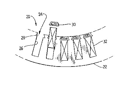
Referring now more particularly to Fig. 3, a portion
--2--

of a dynamo electric machine 18 may be seen having a core
structure 20 made up of a plurality o~ laminations 22 each
having a plurality of slots 24. Each slot 2~ has walls 26 and
has a keyed configuration 28 to receive a wedge 30 to retain a
coil 32 in the slot.
Referring now also to Fig. 4 and 5, tapered wall slots
34 may be formed in core 36. Coils 38, 40 may be random
wound. Coils 38 and 40 are insulated ~rom core 36 as follows.
A slot cell layer of insulation 42 is inserted into slot 34. A
filler material ~4 preferably of a material receptive to resin
impregnation forms a bottom filler 44. Magne~ wires 46 are
inserted into slot 34 to form coil 40. A center filler 48 and
center wedge 50 are placed over coil 40 to separate coil 40
from coil 38. A top filler 52 and top U-wedge 54 are placed
over coil 38. Coils 38 and 40 are preferably vacuum pressure
impregnated with an appropriate insulating resin which also
impregnates the filler material 44. The magnetic top wedge 30
is placed over this assembly at the entrance to slot 34.
Alternatively, wedge 30 may be placed at the entrance to slot
24, if form wound coils are desired to be utilized.
Referring now to Figs. 6, 7 and 8, the structure and
assembly of the maynetic top wedge is as follows. When it is
desired to have a trapezoidal prism-shaped top wedge, a
plurality of ferromagnetic laminations 56 are formed into a
stack 58. Stack 58 is contained within an insulating carrier
60 which may be a hollow extruded plastic channel, for
examyle. Channel or carrier 60 may be sealed at each end by
conventional rneans, such as heat staking. Alternatively, stack
58 may be encapsulated in a plastic or epoxy supporting and
enclosing stack 58 in a final shape 60 suitable for insertion
into the entry of core slot 34. Lamination 56 forms an
extension of the magnetic path across the entry 62 of slot 3~.
Lamination 56 is insulated from core 36 by carrier 60. Carrier
60 is preferably formed of a plastic such as Union Carbide
-3-

Polysulfone P1720NT13 or Dupont Rynite*FRs30, however, any
material compatible with the manufacturing and operating
environment of the machinery in which wedge 30 is to be used
may be selected. In the design illustrated in Fig. 5,
laminations 56 provide an e~tension of the magnetic path across
the slot opening 62, while at the same time providing for a
magnetic gap of predetermined length, preferably equal to two
times the thickness of insulating layer 6~ which is interposed
between each side of the stack 58 and the wall 66 of the slot
opening 62. It is to be understood that the rnagnetic gap
formed by layers 6~ preferably corresponds to gap 10 in
semi-closed slot 8.
Referring now more particularly to Fig. 8, lamination
56 will have a center of gravity 68 located by intersecting
axis 70, 72. Lamination 58 is further formed to include a
notch or opening 74, preferably formed as a keyhole slot.
Opening 74 is located in lamination 56 spaced apart from center
of gravity 68.
Referring now to Fig. 6, a plurality of laminations 56
are threaded onto a filament 76 which may have a deformed or
enlarged end 78. Laminations 56 are threaded onto filament 76
by way of notch 74, which in this embodiment is in the form of
a keyhole opening. When the plurality of laminations 56 are
supported by filament 76, which may be a wire or a non-metallic
member, laminations 56 will Eorm into a congruent stack 58 due
to the action of gravity. Once filaments 56 are formed into
such a congruent stack, they may be inserted into carrier 60,
or impregnated and encapsulated as has been previously
described. If metallic, filament 76 is preferably removed from
stack 58. If filarnent 76 is non-magnetic, it may be left in
stack 58 or withdrawn.
The invention is not to be taken as limited to all of
the ~etails thereof, as modifications and variations thereof
may be made without departing from the spirit or scope of the
* trade-m~rk

invention. For example, and referring to Fig. 9, wedge
laminations 80 may be formed to have a sid~ configuration 82
Iceyed to conform to a slot opening as shown in Fig. 2. In Fig.
9, insulating layer 84 is interposed between side 82 and an
adjacent side of a core lamination wall. Furthermore, the
function of opening 74 may be accomplished by a hole or
aperture 86 which itself is displaced from the center of
gravity the cross-section of lamination 80. Accordingly, what
is claimed is:
~- I! ' '

Representative Drawing
A single figure which represents the drawing illustrating the invention.
Administrative Status

2024-08-01:As part of the Next Generation Patents (NGP) transition, the Canadian Patents Database (CPD) now contains a more detailed Event History, which replicates the Event Log of our new back-office solution.

Please note that "Inactive:" events refers to events no longer in use in our new back-office solution.

For a clearer understanding of the status of the application/patent presented on this page, the site Disclaimer , as well as the definitions for Patent , Event History , Maintenance Fee  and Payment History  should be consulted.

Event History

Description Date
Inactive: Adhoc Request Documented 1994-01-08
Time Limit for Reversal Expired 1993-07-10
Letter Sent 1993-01-08
Grant by Issuance 1991-01-08

Abandonment History

There is no abandonment history.

Owners on Record

Note: Records showing the ownership history in alphabetical order.

Current Owners on Record
MAGNETEK, INC.
Past Owners on Record
BRUCE HEIN
CHARLES SHUFFLEBARGER
Past Owners that do not appear in the "Owners on Record" listing will appear in other documentation within the application.
Documents

To view selected files, please enter reCAPTCHA code :


To view images, click a link in the Document Description column. To download the documents, select one or more checkboxes in the first column and then click the "Download Selected in PDF format (Zip Archive)" or the "Download Selected as Single PDF" button.

List of published and non-published patent-specific documents on the CPD .

If you have any difficulty accessing content, you can call the Client Service Centre at 1-866-997-1936 or send them an e-mail at CIPO Client Service Centre.


Document
Description 
Date
(yyyy-mm-dd) 
Number of pages   Size of Image (KB) 
Claims 1993-10-14 3 92
Drawings 1993-10-14 3 61
Abstract 1993-10-14 1 8
Descriptions 1993-10-14 5 173
Representative drawing 2001-09-25 1 7