Language selection

Search

Patent 1278913 Summary

Third-party information liability

Some of the information on this Web page has been provided by external sources. The Government of Canada is not responsible for the accuracy, reliability or currency of the information supplied by external sources. Users wishing to rely upon this information should consult directly with the source of the information. Content provided by external sources is not subject to official languages, privacy and accessibility requirements.

Claims and Abstract availability

Any discrepancies in the text and image of the Claims and Abstract are due to differing posting times. Text of the Claims and Abstract are posted:

  • At the time the application is open to public inspection;
  • At the time of issue of the patent (grant).
(12) Patent: (11) CA 1278913
(21) Application Number: 1278913
(54) English Title: SHORT-DWELL COATER
(54) French Title: DISPOSITIF DE COUCHAGE A CONTACT ABREGE POUR LE PAPIER
Status: Expired and beyond the Period of Reversal
Bibliographic Data
(51) International Patent Classification (IPC):
  • B05C 11/04 (2006.01)
(72) Inventors :
  • WESTERGARD, SIVERT (Finland)
  • KOIVUKUNNAS, PEKKA (Finland)
(73) Owners :
  • VALMET PAPER MACHINERY INC.
(71) Applicants :
  • VALMET PAPER MACHINERY INC. (Finland)
(74) Agent: NORTON ROSE FULBRIGHT CANADA LLP/S.E.N.C.R.L., S.R.L.
(74) Associate agent:
(45) Issued: 1991-01-15
(22) Filed Date: 1987-07-17
Availability of licence: N/A
Dedicated to the Public: N/A
(25) Language of filing: English

Patent Cooperation Treaty (PCT): No

(30) Application Priority Data:
Application No. Country/Territory Date
863048 (Finland) 1986-07-25

Abstracts

English Abstract


(57) ABSTRACT
This?publication describes a short-dwell coater comprised of
a backing roll (2) used for guiding a paper web (1), with an
upper lip (27) and a lower lip (28) forming a nozzle apparatus
(3), with which the coating mix can-be applied on the paper
web (1) backed by the surface of the backing roll (2), a
doctoring member (6), with which the excess mix applied with
the nozzle apparatus (3) can be doctored, a mounting fixture
(14), to which the doctoring member (6) is mounted, and a
support structure (7), with which the fixture (14) is
supported. In accordance with the invention, the short-dwell
coater comprises an actuator means (15, 16), to which the
nozzle apparatus (3) is attached so that the apparatus is
moveable in relation to the doctoring member (6) in order to
adjust the dwell length (12) between the said doctoring
member and the nozzle apparatus (3).
(Figure 3)


Claims

Note: Claims are shown in the official language in which they were submitted.

The embodiments of the invention in which an exclusive
property or privilege is claimed are defined as follows:
1. A short-dwell coater comprising,
- a backing roll (2) for guiding a paper web (1),
- a nozzle apparatus (3) consisting of an upper lip
(27) and a lower lip (28), with which the coating
mix can be applied to the web (1) backed by the
surface of the backing roll (2),
- a doctoring member (6), with which the excess of
the mix applied with the nozzle apparatus (3) can
be doctored,
- a mounting fixture (14), to which the doctoring
member (6) is attached, and
- a supporting structure (7), by which the fixture
(14) is supported,
c h a r a c t e r i z e d by
- an actuator means (15, 16), to which the nozzle
apparatus (3) is fitted so that it is moveable in
relation to the doctoring member (6) in order to
adjust the dwell length (12) between the said
doctoring member and the nozzle apparatus (3).
2. A short-dwell coater in accordance with claim 1,
c h a r a c t e r i z e d in that the actuator means
(15, 16) comprises a backing roll support lever (15), via
which the nozzle apparatus (3) is rotatably mounted to the
shaft (17) of the backing roll (2) and to an actuator member
(16), rotatingly acting on the backing roll support lever
(15), with which the nozzle apparatus (3) is circularly
moveably in respect to the backing roll (2).

3. A short-dwell coater in accordance with claim 2,
characterized in that the actuator member (16) is a
hydraulic cylinder.
4. A short-dwell coater in accordance with claim 1,
characterized in that the nip between the web (1)
and the upper lip (27) of the nozzle apparatus (3)
attached to the actuator means (15, 16) is adjustable
by a first control member (20), and the distance of the
lower lip (28) from the web is adjustable by a second
control member (22) in order to optimize the coating
result.
5. A short-dwell coater in accordance with claim 4,
characterized in that the lower lip assembly (21, 28)
of the nozzle apparatus (3) is mounted pivotally to
the backing roll support lever (15), and the upper
lip assembly (19, 27) is mounted pivotally to the
lower lip assembly (21, 28) for control purposes.
6. A short-dwell coater in accordance with claim 4 or
5, characterized in that the first actuator member (20)
is an adjustable screw and the second control member
(22) is a hydraulic cylinder.
7. A short-dwell coater in accordance with claim 2 or
3, characterized in that the nip between in that the nip
between the web (1) and the upper lip (27) of the nozzle
apparatus (3) attached to the actuator means (15, 16)
is adjustable by a first control member (20), and the
distance of the lower lip (28) from the web is adjustable
by a second control member (22) in order to optimize the
coating result.

Description

Note: Descriptions are shown in the official language in which they were submitted.


~7~913
Short-awell coater
The present invention relates to a short-dwell coater in
accordance with the preamble of claim 1.
A coater is used for single-sided coating or sizing of a
paper web at different web speeds. The preferred method for
use of the coater is at high speeds when a coating with the
ultimate smoothness is desired. Another preferred application
is in the coating of board at low speeds, in which method a
bent blade is used.
The short-dwell coaters of conventional technology are based
on a constant dwell length.
The short-dwell coaters of present technique have the problem
that sufficiently high coat weights cannot be applied in a
controllable manner on the web. With the extremely short
dwell length in the short-dwell coater, higher coat weights
are aimed at by utilizing overpressure at the application
zone. Conversely, this causes problems with the end seals
and the smoothness of the coat.
The aim of this invention is to overcome the disadvantages
associated with the prior art technology and to achieve a
totally new kind of a short-dwell coater.
The invention is based on optimizing the dwell length to be
as short as possible with the help of a moveable nozzle
apparatus, still, however, retaining the means for applying
a sufficiently thick coat on the web.
More specifically, the method in accordance with the invention
is primarily characterized by what is stated in the
characterizing part of claim 1.
.
~ .
,,, ~
. .

~;~789~3
The invention provides outstanding benefits.
Due to the optimized dwell length, a low moisture content of
the paper web is achieved, which improves the coat quality
and runnability of the paper machine. The coating mix is
applied in sufficient weight onto the base stock in smoother
coats than before while the machine can additionally be run
using both a straight and a bent blade. Furthermore, the end
seals are no longer absolutely mandatory.
The invention is examined in detail with help of the following
-exemplifying embodiments illustrated in the attached drawings.
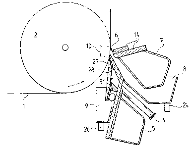
Figure 1 shows in a partly cross-sectional side view a short-
dwell coater in accordance with the invention.
Figure 2 shows in a partly cross-sectional side view a detail
around the point of coat application in the short-dwell
coater illustrated in Figure 1.
Figure 3 shows in a side view an apparatus illustra-ted in
Figure 1, and specifically, an actuator mechanism, in which
the control of dwell length is implemented by supporting the
nozzle apparatus with rotatable arms.
Figure 4 shows in a side view another apparatus in accordance
with the invention having an adjustable angle and nip in
respect to the web.
The cross-sectional view illustrated in Figure 1 shows the
main components of the apparatus. A paper web 1 is adapted to
run upwards in the coater unit. A backing roll 2 rotates at
an angular velocity corresponding to the speed of the web 1.
A feeder pipe 4 conveys the coating mix to a nozzle apparatus
3, consisting of an upper lip 27 and a lower lip 28, which
finally applies the mix onto the web 1. With the help of a
doctoring blade 6, fitted with a blade mounting fixture 14
to a first steel beam 7 operating as a support structure;

~7891;~
the excess mix i5 doctored away and flows to a first tray 8,
from where it can be recirculated via an outlet pipe 24 to
be retreated and reused.
The support structure o~ the nozzle apparatus 3 is another
steel beam 5. Instead of the doctoring blade 6, a doctoring
bar can also be used. -The coat is returned via the nip
between the nozzle apparatus 3 and the web to the tray 9
for recirculation. A portion of the coat is already returned
prior to the nozzle apparatus 3 to another tray g, from
where the excess mix flows via an outlet pipe 26 for retreat-
ment. The nozzle apparatus 3 together with its trays 8, 9
is moveable by means of the blade/beam assembly 6, 7 in
order to adjust a dwell length 12. An application length lO,
shown in Figure 1, is further detailed in Figure 2 into a
doctoring length 13, a dwell length 12 and a nozzle length 11.
Figure 3 shows a possible method for implementing the
adjustment of the dwell length 12. The nozzle apparatus 3
together with its trays 8, 9 is rotatably mounted with a
ba~king roll support lever 15 to a shaft 17 of a backing
roll 2. The backing roll support lever is moveable, for
instance, by a hydraulic cylinder 16 so that a bearing 18 of
the nozzle apparatus 3 at the other end of the backing roll
support lever 15, together with the other components,- is
moved around the perimeter of a circle, whose center point
is the rotation center point of the backing roll 2. In the
apparatus in accordance with the figure, the outward movement
of the hydraulic cylinder 16 shortens the dwell length 12.
With this arrangement, the nozzle apparatus 3 meets the
paper web 1 always at a constant angle, irrespective of the
set dwell length 12, and furthermore, the nip of the nozæle
apparatus 3 with the paper web 1 remains constant.
',~
Figure 4 shows a possible method for implementing the nip
; adjustment of the upper lip 27 and the lower lip 28 with the
web 1 in the apparatus according to the invention~ An upper
.
,.
:~,

7~
--4--
lip lever 19 is rotatably mounted to the backing roll
support lever 15 via a bearing 18. The bearing 18 of the
upper lip lever 19 is located at the opposite end of the
backing roll support lever 15, relative to the bearing
point of a shaf-t 17 of the backing roll 2. With the
help of an adjustment screw 20, the upper lip lever 19
is rotatably moveable about the bearing 18, thus providing
a nip adjustment between the web 1 and the upper lip 27
adapted to the upper lip lever 19. Furthermore, a lower
lip lever 21 is ro-tatably mounted to the upper lip lever
19 with help of a bearing 23. The bearing 23 of the lower
lip lever 21 is located at the opposite end of the upper
lip lever 19, relative to the bearing 18 of the upper lip
lever 19. The lower lip lever 21 is moveable about its
bearing point 23 by means of a hydraulic cylinder 22
connecting the lower ends of the lower lip levex 21 and
the upper lip lever 19 in order to adjust the distance of
the lower lip 28 from the web 1. The adjustments always
provide an optimal position of the nozzle apparatus 3
corresponding to a set dwell length 12.
The movement of the nozzle apparatus 3 can also be
implemented pneumatically, or directly with help of an
electric motor. If the attachment point of the nozzle
apparatus 3 is different from the rotation axis 17 of the
backing roll 2, the position of the nozzle must be
altered when the dwell length 12 is adjusted.
'

Representative Drawing
A single figure which represents the drawing illustrating the invention.
Administrative Status

2024-08-01:As part of the Next Generation Patents (NGP) transition, the Canadian Patents Database (CPD) now contains a more detailed Event History, which replicates the Event Log of our new back-office solution.

Please note that "Inactive:" events refers to events no longer in use in our new back-office solution.

For a clearer understanding of the status of the application/patent presented on this page, the site Disclaimer , as well as the definitions for Patent , Event History , Maintenance Fee  and Payment History  should be consulted.

Event History

Description Date
Time Limit for Reversal Expired 2006-01-16
Letter Sent 2005-01-17
Grant by Issuance 1991-01-15

Abandonment History

There is no abandonment history.

Fee History

Fee Type Anniversary Year Due Date Paid Date
MF (category 1, 7th anniv.) - standard 1998-01-20 1997-12-18
MF (category 1, 8th anniv.) - standard 1999-01-15 1999-01-11
MF (category 1, 9th anniv.) - standard 2000-01-17 2000-01-12
MF (category 1, 10th anniv.) - standard 2001-01-15 2000-11-23
MF (category 1, 11th anniv.) - standard 2002-01-15 2001-12-20
MF (category 1, 12th anniv.) - standard 2003-01-15 2002-12-17
MF (category 1, 13th anniv.) - standard 2004-01-15 2003-12-23
Owners on Record

Note: Records showing the ownership history in alphabetical order.

Current Owners on Record
VALMET PAPER MACHINERY INC.
Past Owners on Record
PEKKA KOIVUKUNNAS
SIVERT WESTERGARD
Past Owners that do not appear in the "Owners on Record" listing will appear in other documentation within the application.
Documents

To view selected files, please enter reCAPTCHA code :


To view images, click a link in the Document Description column. To download the documents, select one or more checkboxes in the first column and then click the "Download Selected in PDF format (Zip Archive)" or the "Download Selected as Single PDF" button.

List of published and non-published patent-specific documents on the CPD .

If you have any difficulty accessing content, you can call the Client Service Centre at 1-866-997-1936 or send them an e-mail at CIPO Client Service Centre.


Document
Description 
Date
(yyyy-mm-dd) 
Number of pages   Size of Image (KB) 
Abstract 1993-10-15 1 21
Cover Page 1993-10-15 1 12
Claims 1993-10-15 2 62
Drawings 1993-10-15 4 82
Descriptions 1993-10-15 4 147
Representative drawing 2001-08-14 1 11
Maintenance Fee Notice 2005-03-14 1 172
Fees 1996-12-11 1 62
Fees 1995-12-07 1 58
Fees 1994-12-08 1 62
Fees 1993-12-10 1 79
Fees 1992-12-09 1 48