Note: Descriptions are shown in the official language in which they were submitted.
~89~
The present invention relates to an aircra~t de-
icing system of the kind which comprises an aircraft-
washing hardstanding which presents an aircraft
carriageway; means for spraying the aircraft with de-icing
fluids and drainage means for collecting and carrying away
the de-icing fluid.
In de-icing systems of this kind, for example
the system illustrated and described in Swedish Patent
Specification 7713619-0, the hardstanding exhibiting the
carriage way must be constructed 50 as to he able to
withstand the heavy load exerted by an aircraft, and 50 as
to enable an aircraft to be moved safely into position in
the ahsence of any disturbing irregularities which might
cause the wingtips of the aircraft to swing and be damaged
by contact with, for example, washing or spraying devi~e~
and the like located in the vicinity of the various
aircraft parts.
At the same time, the arran~ements used to
collect and carry away the large quantities of de-icing
fluid which run down from the aircraft onto the
hardstanding area must be highly effective, without
presenting too much of an obstacle to smooth forward
movement of the aircraft. In addition, it has been fo~nd
that, in the majority of weather conditions, heavy mists
are formed if the used de-icing fluid is not removed and
dispensed with quickly enough, such mists ~eing also
troublesome to those parts of the airfield located in the
vicinity of the de-icing station.
An ohject of the present invention is to provide
a system in which the aforesaid disadvantages are avoided
substantially completely, in a simple and inexpensive
fashion.
Accordingly, the invention provides an aircraft
de-icing system comprising an aircraft-washing
~5 hardstanding incorporating a carriageway for an aircraft,
a stationary or movable portal structure e~tending across
the hardstanding and provided with pipes and nozzles so
po~itioned that an aircraft on the carriageway and said
B ~v~
- . ~
.
. :
~ .
~'789~9
portal structure are mutually movable with the nozzles
located at a predetermined distance from the various parts
of the aircraft, and means, such as pumps, tanks, filters
and valves for pumping de-icing fluid under high pressure
5 to said pipes and nozzles, the hardstanding comprising a
substantially planar surface layer structured from a
liquid-permeable road-surfacing material, and under said
surface layer an impervious layer which slopes towards
drainage pipes connected to a pump for collecting and
10 carrying away the de-icing fluid and removing water vapour
from the liquid permeable surface layer by suction.
With a hardstanding constructed in this manner,
the de-icing fluid running down onto the surface layer will
pass directly through said surface layer, which can
15 consequently be of planar configuration, since the
arrangements and devices for collecting and carrying away
the de-icing fluid are located beneath the surface layer.
A hardstanding of this construction also affords
the important advantage of enabling the drainage pipes to
20 be connected to a pump arranged to remove water vapour from
the liquid-permeable surface layer by suction. In this way
water vapour is prevented, to a large extent, from rising
up from the aircraft-washing hardstanding and sweeping into
the aircraft in the form of a vapour cloud, which is o~
25 considerable benefit with respect to process performance
and with respect to the general visibility in busy and
crowded airfields. The surface layer also serves as a
coarse filter, in which leaves, twigs etc. can be caught.
The suction pump is therefore suitably adapted for
30 switching to a mode in which air is temporarily blown
through the drainage pipes and up through the outer
surface, so that any foreign objects present can be blown
free from the channels and passageways of the surface
layer. Preferably, cold ambient air, or optionally chilled
35 air is blown through said passageways for a suitable length
of time immediately prior to commencing a de-icing process,
which normally takes about three minutes to complete. This
affords the advantage of cooling the
8979
2a
~urfacç layer and the drainage and discharge pip~s to an
extent sufficient to cool the water vapour sucked down
through the surfaGe layer throughout the whole of the de-
icing process, 50 that the water contained in the water
vapour condenses prior to the water vapour reaching the
pump in the machine room.
~' -`'' ~
: ' , . ,
; ' ' , -
.' .
~89~3
Embodiments of the invention will now be
described in more detail with reference to the
accompanyin~ drawin~, which is a perspective view, partly
in section, of an embodiment of a de-icing system
according to the invention.
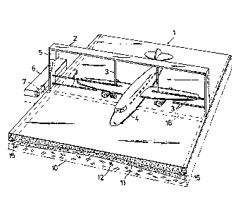
The drawing illustrates an elongated rectangular
aircraft-washing hardstanding 1 which is situated on an
airfield, suitably with direct access to the aircraft
approach path leading from the airfield buildings to the
aircraft runways~ The hardstanding 1, has a breadth which
is slightly larger than the wing span of the largest
aircraft which can be expected for treatment, and
extending across the hardstanding is a portal 2 provided
with pipes and nozzles 3 so positioned that an aircraft ~
rolling onto the hardstanding 1 is able to pass through
the portal with the nozzles located at a pre-determined
distance from the various parts of the aircraft,
particularly from the upper and lower surfaces of the
wings of the aircraft. Located on one side of the portal
2 is a supervising cabin 5. Located adjacent the cabin 5
is a partially submerged machine room 6, to which the
pipes 3 provided with the aforesaid spray nozzles extend.
The hardstanding 1 is constructed of three
mutually different layers, namely a bottom supporting
layer 10, an impervious layer 11 which is located above
the support layer 10 and comprises a liquid-impermeable
material, such as concrete, and which slopes steeply from
both sides of the center line of the hardstanding 1, and
finally a top surface layer 12 which comprises a liquid-
permeable ~aterial, such as a road surfacing material, for
example drainage asphalt, and which has a sub~tantially
planar top surface.
The liquid-permeable material is suitably a hot-
mixed (150-170C) asphalt concrete having cavities of 15-
20~ and about 60% ballast material of largest ballast
fraction, and a fibre addition which increases the
compression strength of the material and its length of
useful life.
..... , . ; ~. . . .
~7~3g~
Drainage pipes 15 are embedded in the
longitudinal edges of the impervious layer 11 around the
hardstanding 1, so that all liquid penetrating down
through the surface ayer 12 and running over the
impervious layer is collected in the drainage pipes 15.
The drainage pipes 15 are connected to the
machine room 6 by means of discharge pipes 16. The
machine room 6 houses an arrangement of pumps, tanks,
filters, valves etc. for pumping under high pressure a
water-glycol-mixture of varying concentration to the pipes
3 and the nozzles as the aircraft is 510wly moved through
the portal 2. All surfaces of the aircraft are contacted
by the liquid jets in accordance with a pre-determined
program, whereupon ice and snow are loosened and washed
from the aircraft and fall onto the hardstanding 1
together with the de-icing fluid, after which the fluid
and the molten snow and ice quickly pass through the
surface layer 12 onto the impervious layer 11 and from
there through the drainage pipes 15 and the discharge
pipes 16 to the machine room 6, where the fluid is
reconditioned and strengthened to the desired
concentration for renewed pumping to the pipes 3 and
nozzles of the portal 2.
The machine room 6 also houses a large-capacity
vacuum pump ~ which is connected to the discharge pipes
16, this vacuum pump being actuated to draw a flow of air
downwardly through the surface liayer 12. Tho~e clouds of
water vapour which would otherwise rise up from the
hardstanding 1 and which derive from the relatively warm
de-icing fluid in cold weather will thereby be drawn
through the drainage and discharge pipes 15, 16 instead,
which is an important feature of the invention.
The portal 2 need not be an immovable structure,
but may be arranged for movement in the longitudinal
direction of the hardstanding 1, in which case the
aircraft can be allowed to remain stationary during the
de-icing process.
,
,
'