Note: Descriptions are shown in the official language in which they were submitted.
1~789~
METHOD AND APPARATUS FOR
FORMING A LOOP WITH END-GRIPPED STRAP
TECHNICAL FIELD
This invention relates to the formation of a
loop of flexible binding or strapping material. Such
loop formation may be employed during the process of
binding an object, such as a package or one or more
articles.
BACKGROUND OF THE INVENTION
AND
TECHNICAL PRO~LEMS POSED BY THE PRIOR ART
Disclosures have been made of methods and
apparatus for forming a strap loop which may
ultimately be used to bind a package or other
object. For example, see U.S. patent numbers Re.
31,353, 4,077,313~ 4,079,667, and 4,378,262. While
the methods and apparatus disclosed in these patents
function well with respect to the applications for
which they are intended, it would be desirable to
provide an improved method and apparatus for
accommodating a variety of types of s~rap.
In particular, it would be advantageous to
provide an improved method and apparatus that is
particularly suitable for very thin strap such as
"film" s~rap. It would also be beneficial if such an
improved apparatus could be embodied in a relatively
small, portable unit.
SUMMARY OF THE INVENTION
A method is provided for forming a loop of
strap for encompassing an article. A length of strap
is fed to orient a segment between two spaced-apart
gripping members. The strap segment is gripped with
the gripping members by effecting relative movement
between the gripping members to clamp the strap
segments between the gripping members. While
~':
' ~
:: :
89~
continuiny to yrip the strap segment, the gripping members are
moved together in a closed path to ~orm a primary loop in the
strap around at least one of the gripping members. Next, while
still continuing to grip the strap segment, the strap is fed to
expand the primary loop to an expanded loop having a larger
size ~or accommodating the article.
In the disclosed apparatus, the two gripping members
are mounted on the frame for movement together in the closed
path. Means are provided for effecting the relatlve movement
between the grlpping members to cause the strap segment to be
clamped. Means are also provided on the frame for moving the
two gripping members together in the closed path. A strap
drive means is provided ~or feeding the strap to expand the
loop.
The method of the invention maybe summarlzed as
comprisiny the steps of: (a) feeding a length of strap to
orient a segment between two spaced-apart gripping members;
(b) gripping said strap segment with said gripping members by
effecting relative movement between said gripping members to a
clamping orientation to clamp said strap segment between said
gripping members; (c) while continuing step (b), moving both of
said gripping members together in the clamping orientation in a
closed path to ~orm a primary loop in said strap around at
least one of said grippiny membèrs; and (d) while continuiny
step (b), feeding said strap to expand said primary loop to an
expanded loop having a larger size for accommodating said
article.
Apparatus according to the invention ma~he summarized
as comprising: a frame and two gripping members mounted on said
frame for movement together in a closed path; means for
e~ecting relative movement between said gripping members to a
clamping orientation to clamp a segment of said strap between
.~ .
8'~
said gripping members; means on said frame for moving said two
gripping members together in said closed path, while fixe~
relative to each other in the clamping orientation with said
strap segment clamped between said two gripping members, to
form a primary loop ~n said strap around at least one of said
~ripping members; and strap drive means for feeding said strap
to expand said primary loop to an expanded loop having a larger
size for accommodating said article.
Numerous other advantages and features of the present
invention will become readily apparent from the following
detailed description of the invention, from ths claims, and
from the accompanying drawings.
B~IEF DESCRIPTION OF THE DRAWINGS
In the accompanying drawings forming part of the
speciflcation, in which like numerals are employed to designate
like parts throughout the same,
Figure 1 is a simplified, fragmentary, front
elevation view of the apparatus of the present invention with
some portions of the strap and apparatus broken awa~ to hette~
illustrate underlying detail;
Figure 2 is a fragmentary, plan view taken in partial
; cross-section generally along the plane 2-2 in Figure 1;
Figure 3 is a simplified, cross-sectional view of the
apparatus taken generally along the plane 3-3 in Figure 2;
:: 30
~:~ 2a
.:
:
~ ~78~39~
Figure 4 is a simplified, fragmentary, end
view taken generally along the plane 4-4 in Figure 2;
Figure 5 is a greatly enlarged, fragmentary,
cross-sectional view of the traction wheel and
back-up wheel assembly ta~en generally along plane
5-5 in Figure 2
Figure 6 is a fragmentary, cross-sectional
view taken generally along the plane 6-6 in Figure 5;
Figure 7 is a view similar to Figure 5, but
showing the back-up wheel in a moved position
disengaged from the traction wheel;
Figure 8 i5 a fragmentary, cross-sectional
view taken generally along the plane 8-8 in Figure 7;
Figure 9 is a greatly enlarged, partial,
lS cross-sectional view of the gripping member assembly;
Figure 10 is a fragmentary, cross-sectional
view taken generally along the plane 10-10 in Figure
9;
Figure 11 is a greatly enlarged,
fragmentary, partial cross-sectional view taken along
the plane 11-11 in Figure 10;
Figure 12 is agreatly enlarged, fragmentary,
partial cross-sectional view taken generally along
the plane 12-12 in Figure 10;
Figure 13 is an enlarged, fragmentary,
exploded, perspective view of the gripping member
assembly illustrated in Figures 9-12;
Figures 14A, 14B, 14C, 14D, 14E, 14F, 14G,
~:~ 14H, and 141 are simplified, fragmentary, front
elevation views illustrating the operational sequence
: of the illustr~ted preferrèd embodiment of the
apparatus of the present invention according to one
; ~ form of the method of the present invention; and
Figures 14A', 14B', 14C', and 14D' are rear
elevation views of the gripping member assembly of
.,
,',~
~:
::
.
. ~ ~
~ ~789~t~
--4--
the apparatus shown in an operating sequence
corresponding with the sequence of operation
illustrated in Figures 14A, 14~, 14~, and 14D,
respectively.
DESCRIPTION OF THE PREFERRED EMBODIMENT
While this invention is susceptible of
embodiment in many different forms, this
specification and the accompanying drawings disclose
only one specific form as an example of the use of
the invention. The invention is not intended to be
limited to the embodiments so described, and the
scope of the invention will be pointed out in the
appended claims.
--The Apparatus
For ease of description, the disclosed novel
apparatus is described in the normal (upright)
operating position, and terms such as upper, lower,
horizontal, etc., are used with reference to this
position. It will be understood, however, that the
novel apparatus may be manufactured, stored,
transported, used, and sold in an orientation other
than the exact orientation described.
The apparatus of this invention is used
with, or includes, certain conventional components
and control mechanisms, the details of which,
although not fully illustrated or described, will be
apparent to those having skill in the art and an
understanding of the necessary functions of such
- components and control mechanisms.
Some of the figures illustrating the
apparatus show conventional structural details and
mechanical elements that will be recognized by one
skilled in the art. However, the detailed
descriptions of such conventional elements are not
necessary to an understanding of the invention, and
accordingly, are not herein presented.
~.X~899~
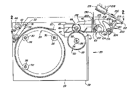
Referring now to Figure 1, the novel strap
loop-forming apparatus of the present invention is
designated generally by reference numeral 20. The
apparatus 20 includes a frame 28 defining a generally
planar base contact surface 29 for being placed on a
suitable support surface S (Figure 14E), such as a
table top.
Although the apparatus 20 may be used to
form a loop in a variety of binding or strapping
materials, it is especially suitable for forming a
loop from non-metallic, thin film strap, such as
strap having a thickness of less than about ~.13 mm.
(0.005 in.). Such strap is designated generally in
the figures by reference numeral 22. Such strap 22
may be fabricated from polypropylene, polyester,
nylon, or other suitable materials.
A presently preferred form of such strap 22
is polypropylene strap having a thickness of 0.08 mm.
(0.003 in.) and a width of 19.05 mm. (0.75 in.).
Such film is extremely flexible. It cannot be easily
pushed through a conventional strap chute. It does
not, by itself, maintain an open, circular loop of
significant size when the loop hangs downwardly under
the influence of gravity. Novel methods and means
are required for forming a useful loop of such strap
for conventional low tension binding applications.
With continued reference to Figure 1, it is
seen that the strap 22 is preferably provided on a
strap reel 24 which may be mounted on suitable
- 30 support studs 26 projecting from the front of the
apparatus frame 23. Suitable retaining members, such
as washers 3D, are disposed on each stud 26 for
retaining the reel 24 in proper position. The studs
26 and the washers 30 may be removed when desired to
accommodate removal of the strap reel 24 and
replacement with a new reel.
`;
.
'1.~,~89~;
--6--
~ n the simplest form contemplated by the
present invention, the strap reel 24 may be freely
rotatable on the studs 26 about the central axis of
the reel 24. However, if desired, conventional or
special snubbing and/or retracting mechanisms may be
incorpora~ed. For example, a friction snubbing
device 32 may be provided as illustrated in Figures 1
and 2. The device 32 includes an arm 34 pivotally
mounted about a pin 36 to the frame 28. The distal
end of the arm 34 carries a roller 38 rotatably
mounted about a pin 40 that is disposed on the arm
34. The arm 34 is biased against the outer layer of
strap 22 on the reel 24 by a spring 42 which is
carried on a mounting block 44 on the frame 28.
When the strap 22 is withdrawn (pulled
forwardly) off the reel (clockwise as viewed in
Figure 1) by means described in detail hereinafter,
the roller 38 acts as a snubber or friction brak~ to
prevent over-rotation of the reel 24 when the pulling
force on the strap 22 is terminated.
Additionally, or alternatively, the reel 24
could include a conventional or special strap
retracting means (not illustrated). Such a
retracting means would function in the well-known amd
conventional manner to apply counter-torque or
retracting torque to the reel 24 so as to oppose the
strap withdrawing torque. The retracting torque
would be relatively low and could be easily overcome
by the strap withdrawing torque. However, when the
3~ strap withdrawing torque falls below a predetermined
magnitude, the retracting means would cause the reel
24 to rotate (in the counterclockwise direction as
viewed in Figure 1) to rewind the strap 22. The
detailed design and specific structure of such a
conventional or special retracting means form no part
of the present invention.
;
~ .
':
.
~J789g~
As best illustrated in Figures 1 and 5-8,
the apparatus 20 includes a traction wheel 50.
Preferably the traction wheel 50 has a molded
polyurethane periphery 52 which may be grooved. In
some applications, an O-ring of conventional
manufacture may be employed in place of the molded
polyurethane periphery. Other compositions and
structures may be provided for the traction wheel 50,
depending upon, inter alia, the type of strap, the
strap width and thickness, the surface speed of the
wheel, and the operating force of the strap 22
against the wheel.
~ he traction wheel 50 is mounted on a hub 54
by means of a key 56, and the hub 54 is mounted on a
shaft 58 which is journaled for rotation in a
mounting block 60 (Figures 6 and 7). A motor 62
(Figures 2 and 4) is operably connected with the
shaft 58 for rotating the traction wheel 50 in either
direction. The motor 62 is appropriately mounted to
a suitable frame portion which is only
diagrammatically illustrated in Figures 2 and 4 by
the slanted lines 64.
A back-up wheel 66 is mounted above the
traction wheel 50 for rotation on a shaft 68 which is
eccentrically mounted to the end of an enlarged
cylindrical portion 70 of a shaft 72. As best
illustrated in Figure 3, the shaft 72 is journaled in
the mounting block 60 and is connected on its distal
end at the rear of the apparatus 20 to a rod 74 which
is in turn connected to an actuator rod 76 of an
electric solenoid actuator 78 which is mounted with a
bracket 80 to a portion of the frame 28.
With reference to Figures 5 and 6, it can be
seen that the axis 82 of the back-up wheel shaft 68
is laterally offset with respect to the axis 84 of
'~
,
:
lX7899~i
--8--
the enlarged end portion 79 of the shaft 72. The
back-up wheel 66 is thus eccentrically movable
between a first position (illustrated in Figures 5
and 6) wherein the back-up wheel 66 engages the
traction wheel 50 and a second position (illustrated
in Figures 7 and 8) wherein the back-up wheel 66 is
spaced away from the traction wheel 50.
The movement of the back-up wheel 66 is
effected by actuation of the solenoid actuator 78
(Figures 2 and 3). The actuator 78 may have an
internal spring (not illustrated) for normally
maintaining the actuator rod 76 in the fully
retracted position so as to normally bias the back-up
wheel 66 against the traction wheel S0. Energization
of ~he actuator 78 extends the rod 76 (in the
direction of arrow 85 in Figure 3) to raise the
back-up wheel 66 away from the traction wheel 50.
When the back-up wheel 66 is moved toward
engagement with the traction wheel 50 as illustrated
in Figure 5, the strap (not illustrated in Figures
5-8) would be urged by the back-up wheel 66 aqainst
the traction wheel 50 (with a small force). On the
other hand, when the back-up wheel 66 is moved away
from the traction wheel 50 (as illustrated in Figures
7 and 8), the strap would not be sufficiently
frictionally engaged with the surface of the traction
wheel 50 to effect movement of the strap when the
traction wheel is rotating.
Since the traction wheel 50 may be operated
: 30 in either direction of rotation, the traction wheel
50 can function as a feeding means for feeding the
strap forwardly (to the right as viewed in Figure 1)
: and subsequently as a strap retracting or tensioning
means for retracting the strap rearwardly (to the
left as viewed in Figure 1). The traction wheel
~`
~ ~7899~
motor 62 may be a conventional electric motor and may
be controlled through a conventional control system
for rotation as necessary in either direction.
However, it is to be realized that the traction wheel
50 need not be rotated by a separate, dedicated
motor, such as motor 62. If desired, the traction
wheel 50 could be rotated through a suitable drive
system from a prime mover (not illustrated) that
could also function to operate other subassemblies in
the apparatus 20 (either simultaneously and/or
sequentially).
As illustrated generally in Figures 1 and
14A, the strap 22 is withdrawn from the strap reel 24
and extends over the traction wheel 50 to a gripping
member assembly 100. As best illustrated in Figures
5 and 6, â channel 45 is provided for receiving the
strap 22 adjacent the traction wheel 50, and the
channel 45 is defined on the top by guide blocks 46
and on the bottom by guide blocks 47. The strap 22
is guided on its inner lateral edge on the inside of
the apparatus 20 by the block 60 (Figures 6 and 7).
The outer lateral edge of the strap 22 is guided on
~ the outside of the apparatus 20 by a transparent
plate 48 (visible in Figure 1, but omitted from
Figures 5-8).
The gripping member assembly 100 is provided
for gripping a segment of the strap 22 and moving the
strap segment in a closed path to form a primary loop
which is subsequently expanded to a larger size. The
gripping assembly 100 is illustrated in detail in the
exploded perspective view of Figure 13 and in the
cross-sectional views of Figures of 9-12.
With reference to Figures 10 and 13, it is
seen that two gripping members are provided, a
gripper arm 101 and an anvil 102. The gripper arm
~ .
789~
--10--
101 is mounted with screws 103 to a generally
cylindrical portion 104 on a first shaft 105 that is
mounted for rotation relative to the apparatus
frame. The anvil 102 extends from a generally
cylindrical portion 106 that is disposed at the end
of a hollow, second shaf~ 107. The hollow, second
shaft 107 is mounted concentrically on the first
shaft 105 ~or rotation relative to the fir~t shaft
105. As best illustrated in Figure 4, the exterior
of the second shaft 107 is journaled for rotation in
depending flanges 108 of a portion of the frame 28.
With reference to Figures 9 and 13, it is
seen that the generally cylindrical portion 104 on
the end of the first shaft 105 defines two recesses
110, and each recess 110 receives an end of a
compression spring 112. The cylindrical portion 104,
along with the springs 112, is received within a
cavity 114 of the generally cylindrical portion 106
on the end of the second shaft 107. The outer end of
each spring 112 is received within a bore 11~ of the
generally cylindrical portion 106. The upper spring
112 is retained in position in the generally
; cylindrical portion 106 by a roll pin 118, and the
lower spring 112 is retained in position in the
generally cylindrical portion 106 by a screw 120
engaged with the portion 106.
With reference to figures 9, 10, and 13, it
can be seen that if the inner shaft 105 is prevented
from rotating, the springs 112 would function to
rotate the generally cylindrical portion 106
~: (clockwise as viewed in Figure 9) so as to move the
anvil 102 toward the gripper arm 101. A mechanism
for permitting such action is next described.
The rearward end of the second, hollow shaft
107 is shorter than the first shaft 105, and the
":~
.~ .
~.~J~399~i
first shaft 105 extends rearwardly beyond the second
shaf~ 107. A first annular member 124 (Figures
10-13) is mounted on the end of the first shaft 105 .
and is secured to a shaft 126 (Figures 2 and 4) of a
suitable rotating drive means which may be in the
form of a motor 128. The motor 128 is mounted to a
suitable portion of the frame 28, and such a suitable
mounting portion is only diagrammatically illustrated
by slanted lines 130 in Figures 2 and 4.
Although not illustrated, it may be
preferable to eliminate the motor 128 and rotate the
gripping member shaft 126 through appropriate
conventional gear, chain, or belt drive elements from
the traction wheel motor 62. Alternatively, the
shaft 126 may be rotated directly by a separate
electric solenoid operator or by other suitable means.
The first generally annular member 124 is
secured with suitable set screws 132 to the first
shaft 105. The first annular member 124 includes a
cylindrical surface defining first detent element
with a notch 134, the purpose of which will be
described in detail hereinafter.
A second generally annular member 138 is
mounted with set screws 140 to the hollow, second
25 shaft 107. The second annular member 138 includes a
cylindrical surface that defines a second detent
element with a notch 142 and a third detent element
with a notch 143.
As best illustrated in Figures 11-13, the
; 30 apparatus 20 also includes a first pawl 151, a second
pawl 152, and a third pawl 153. Each pawl is
pivotally mounted to the frame 28. With reference to
Figures 11 and 12, the first pawl 151 and the third
pawl 153 are seen to be pivotally mounted about a
35 common pin 154. The second pawl 152 is pivotally
mounted about a pin 155.
~ ~7~39~13~;
-12-
The apparatus 20 also includes a first
biasing means or spring 161, a second biasing means
or spring 162, and a third biasing means or spring
163 to effect engagement of the first pawl 151, the
second pawl 152, and the third pawl 153,
respectively, with the first detent element notch
134, the second detent element notch 142, and the
third detent element notch 143, respectively. The
first spring 161 is received in a first bore 165 in a
block 166 mounted to the frame 28. The third spring
163 is similarly received in an adjacent bore 167 in
the block 166. The spring 162 is received in a bore
168 in a block 169 which is also mounted to the frame
28.
With reference to Figures 11 and 13, it can
be seen that a member 170 is provided for pivoting
the second pawl 152 out of the detent element no~ch
142 against the compression spring 162 and toward the
block 169. The member 170 is carried on an arm 172
(Figures 11 and 3) which is pivotally mounted on a
pin 174 (Figure 3) to the frame 28. The other end of
the arm 172 is pivotally connected by a pin 176 to an
actuator arm 178 of an electric solenoid actuator
180. The actuator 180 is mounted with a bracket 181
to the frame 28. Energization of the solenoid
actuator 180 causes the arm 178 to move downwardly
(in the direction of arrow 182 in Figure 3) to effect
~:~ the pivoting action of the second pawl 152 out of
; engagement with the second detent element notch 142.
. 30 Of course, the actuator 180 may be replaced by other
suitable conventional or special means (not
illustrated) for effecting the pivoting action of the
: second pawl 152.
A joint forming assembly 200 (Figures 1 and
; 35 3) is provided for cooperating with the anvil 102 to
:
:: :
t~899~i
form a joint in overlapping portions of the strap
after the strap loop is formed in a manner described
in detail hereinafter. The join~ forming assembly
200 includes suitable strap contac~ing or joining
member 202 tFigure 1) that is pivotally mounted about
a pin 204 on the frame 28. A torsion spring 206 is
disposed around the pin 204. One end of the spring
206 engages the bottom of the strap contacting member
202, and the other end of the spring engages a fixed
pin 208. The spring 206 acts to bias the strap
contacting member 202 upwardly away from the anvil
102.
An actuating arm 210 is mounted to one end
of the strap contacting member 202 and is adapted to
be engaged by a foot 212 carried at the end of an
actuator rod 214 of an electric solenoid actuator
216. The electric solenoid actuator 216 is mounted
to a suitable portion of the frame which is only
diagrammatically illustrated in Figures 1 and 3 by
the slanted lines 218.
With reference to Figure 1, it can be seen
that actuation of the electric solenoid actuator 216
to retract the rod 214 in the direction of arrow 220
will cause the strap contacting member 202 to pivot
downwardly toward the anvil 102.
The strap contacting member 202 may employ
any suitable means for joining overlapping strap
portions after the strap loop is formed by means
described in detail hereinafter. For example, the
strap contacting member 202 may include a vibrating
mechanism for effecting a friction-fusion ~eld joint
. of the overlapping strap portions. Alternatively,
; ~ the strap contacting member 202 may contain a
suitable conventional ultrasonic welding meshanism or
a suitable heating mechanism for producing a joint.
~ ~7~39~i
The formation of the joint per se, and the mechanism
for orming the joint, form no part of the broadest
aspects of the present invention.
Me~ns may be provided, if desired, for
automatically severing the trailing portion of the
strap 22 from the strap loop. In the preferred
embodiment of the apparatus illustrated, an
automatically actuated knife mechanism is provided
for this purpose. Specifically, as best illustrated
in Figures 1 and 4, a knife blade 230 is provided for
being maintained in a normally unactuated, vertical
orientation between the strap gripping member
assembly 100 and the traction wheel 50.
The blade 230 is pivotally connected to the
apparatus frame near the bottom of the blade 230
about a suitable pivot pin (not visible in the
figures). The blade 230 is also pivotably connected
at the top, by means of a pin 232, to the end of an
actuating rod 234 of an electric solenoid actuator
236. As illustrated in Figure 4, the actuator 236 is
pivotally mounted at its distal end by means of a pin
238 to a suitable portion of the apparatus frame
which is diagrammatically illustrated in Figure 4 by
the slanted lines 240.
Actuation of the actuator 236 to extend the
actuator rod 234 causes the knife blade 230 to pivot
downwardly to a substantially horizontal position
(illustrated in cross-section in Figure 14H). In the
lowered position, the leading edge of the blade 230
is sufficiently below the path of travel of the
trailing portion of the strap 22 so as to effect a
severing of the strap. Preferably, a blade guard
plate 250 ~Figures 1 and 4) is provided on one side
of the knife blade 230 and functions to block access
to the knife blade'movement path.
~L~,78'~
-15-
--Operation Of The Apparatus According To The Method
Of The Invention
The sequence of operation of the apparatus
20 is next described. While the apparatus 20
functions to form a primary strap loop and then
expand the primary loop to a larger size in
accordance with the teachings of the invention, the
apparatus 20 preferably also functions to effect a
complete strapping cycle wherein an article is bound
with a tensioned loop of strap. This involves
feeding a length of the strap from which the loop can
be formed, effecting formation of the loop in a
convenient orientation for accommodating the article
: within the loop, tensioning the loop tight about the
article, joining the overlapping strap portions of
the tensioned loop, and severing ~before or after
joint formation) the trailing portion of the strap
~ from the tensioned loop.
: A typical operating cycle of the apparatus
20 20 is sequentially illustrated in Figures 14A-14I.
The apparatus 20 is ready to start a new strapping
cycle when the apparatus mechanisms are in an initial
or "start" position or condition as generally
illustrated in Figure 14A. Figure 14A corresponds to
25 Figure 1, but in Figure 14A the strap 22 is shown
threaded ~etween the traction wheel 50 and back-up
wheel 66 and as having the leading end of the strap
positioned on top of the anvil 102 below the gripper
arm 101.
Figure 14A' illustrates the initial
positions of the annular members 124 and 138 and of
the pawls 151, 152, and 153, which initial positions
are identical to those positions illustrated in
Figures 11 and 12 as described above in detail. In
35 these initial positions, pawls 152 und 153 prevent
. .
. ~ ~
, ~
~789~3~i
rotation of the anvil 1~2 in either direction, and
pawl 151 prevents rotation of the gripper arm 101
toward the anvil 102 (counterclockwise as viewed in
Figures 9 and 14A).
The new strapping cycle is initiated by
actuation of a suitable control system (not
illustrated). First, the electric solenoid actuator
180 tFigure 3) is energized to pivot link member 172
downwardly. This causes the member 170, carried by
the link member 172, to pivot the second pawl 152 out
of engagement with the second detent element notch
142 as illustrated in Figure 14B~
With the annular member 138 now unlatched,
the springs 112, which act between the gripper arm
first shaft 105 and the anvil second shaft 107
(Figures 9, 10, and 13), urge the second shaft 107 to
rotate (counterclockwise as viewed in Figure 14B).
The anvil 102, mounted on shaft 107, rotates toward
the gripper arm 101 to clamp the segment of strap
22. (The pawl 151 (Figure 14B') remains engaged with
the annular member 124 and thereby prevents rotation
of the first shaft 105 and gripper arm 101 relative
to the second shaft 107 and anvil 102.) When the
anvil 102 is in the "clamping" position (Figure 14B),
the annular member 138 is in a moved, or
incrementally rotated, position that is out of
registry with the annular member 124. That is,
annular member 138 has been rotated to move the
notches 142 and 143 so that notch 143 is no longer in
registry with the notch 134 of the adjacent annular
member 124 (Figure 14B').
~ After the anvil 102 and the connected
:~ annular member 138 rotate to the "clamping" position
as illustrated in Figures 14B and 14B', the electric
: 35 solenoid actuator 180 (Figure 3) is deenergized.
1~7~9~
-17-
However, the pawl 152 remains cammed outwardly by the
cylindrical surface of the annular member 138.
Next, the motor 128 (Figures 2 and 4) is
energized in response to the control system to effect
rotation of the gripper arm first shaft 105 in the
counterclockwise direction as viewed in Figures 14B'
and 14C'. This rotation corresponds to the clockwise
direction of rotation of the gripper arm 101 when
viewing the apparatus 20 from the front as
illustrated in Figures 14B and 14C.
Since the anvil 102 is biased by the springs
112 to clamp the strap 22 against the gripper arm
101, the second shaft 107 and anvil 102 extending
therefrom rotate in the clamping relationship with
the gripper arm 101. The annular members 124 and
138, along with their connected shafts 105 and 107,
respectively, rotate together (but out of registry
owing to the initial incremental rotation of the
annular member 138 that occurred when the anvil 102
initially clamped the strap 22 against the gripper
arm 101).
Figures 14C and 14C' show the anvil 102 and
arm 101 rotated a little more than 180 from the
initial position illustrated in Figures 14A and 14A',
and Figure 14C' shows how the pawls 152 and 153 are
cammed outwardly by the cylindrical surface of the
annular member 138 and how the pawl 151 is cammed
outwardly by the cylindrical surface of the annular
member 124.
As best illustrated in Figures 14C and 14D,
rotation of the gripper member assembly 100 causes
the strap 22 to form a loop about the anvil 102.
During rotation of the gripper member assembly 100,
the strap 22 is pulled off of the strap reel 24. The
traction wheel 50 need not be rotated by motor 62 as
. ~7~399
--18--
the strap 22 is pulled off of the strap reel 24 by the
rotating gripper member assembly 100 if the back-up wheel
66 is elevated to accommodate the pulling of the strap 22
over the top of the traction wheel 50. However, the
traction wheel 50 is preferably also simultaneously
rotated to feed the strap forward. To this end, the
back-up wheel 66 is maintained in the lowered position,
and the traction wheel motor 62 is energized substantially
simultaneously with the energization of the gripper
assembly motor 128.
Further, the traction wheel motor 62 is
preferably operated to rotate the traction wheel 50 at a
speed sufficient to feed the strap 22 at a rate greater
than that re~uired to accommodate the rotation of the
gripper assembly 100. Specifically, it is desired to
provide enough strap around the anvil 102 so that the
initial, primary loop formed about the anvil 102 is
somewhat larger than the anvil 102. This prevents
the strap 22 from being tightly wrapped around the
anvil 102. Tightly wrapping the loop of strap 22
around the anvil 102 could, with some types of straps
(e.g., thin film strap), cause excessive forces to be
imposed on the strap and/or cause the strap to crease.
After the gripper member assembly 100 has
been rotated to the position illustrated in Figure
14D, the annular member 138 is again in its initial
orientation wherein the detent notch 142 is aligned
to receive the pawl 152 which is biased into
engagement with the notch 142 by the spring 162.
Since the electric solenoid actuator 180 (Figure 3)
has been previously deenergized, the member 170 and
link arm 172 connected to the actuator 180 afford no
substantial resistance to the return of the pawl 152
to its original latching position as illustrated in
Figure 14D'.
. ~ .
,; , .
~ ~7~399~i
--19--
At this point, the gripper assembly motor
128 is deenergized and its rotation terminated by a
suitable electric brake (not illustrated) or other
suitable means. ~lthough the third pawl 153 is also
biased back into engagement with the notch 143 on the
annular member 138 (Figure 11) by the spring 163, the
first pawl 151 remains cammed outwardly against the
outer cylindrical surface of the annular member 124.
The annular member 124 is still maintained out of
registry relative to the annular member 138 by means
of the clamping springs 112 (Figures 13 and 14B).
Although the rotation of the gripper
assembly motor 128 is terminated at this point, the
traction motor 62 continues to rotate the traction
wheel 50 to ~eed the strap 22 forward so as to expand
the primary loop to an expanded loop having a larger
size for accommodating an article A as illustrated in
Figure 14E. Preferably, as best illustrated in
Figure 14E, the apparatus 20 has been positioned with
the generally planar base contact surface 29 on a
support surface S (such as the top of a table or the
like). The gripper member assembly 100 is thus
cantilevered over the support surface S, and the
expanding lo~p of strap 22 is free to grow
downwardly.
If desired, the gripper member assembly 100
could be located near the bottom of the apparatus 20
in a non-cantilevered orientation with the "at rest"
ini~ial position of the gripper member assembly 100
being oriented 180 degrees from the position
~; illustrated in Figure 1. This would permit the loop
of strap 22 to expand upwardly.
In any case, before the article A is placed
within the loop, the loop is allowed to grow to the
desired size. Typically, in the illustrated
.
,
, . :
~.~,7~3~9~
-20-
embodiment of the apparatus 20, the bottom of the
loop would contact the support surface S, and this
would cause the sides of the strap loop to bow
outwardly. One side of the strap loop would
eventually come to rest against the vertical side of
the apparatus frame 28, and the other side of the
strap loop, being unrestrained, would bow outwardly a
greater amount. This results in the formation of a
strap loop having a somewhat rectangular
configuration which more easily accommodates an
article A having a typical rectangular shape.
After the article A has been positioned
within the expanded loop of strap 22, the strap loop
is tensioned about the article as best illustrated in
Figure 14F. To this end, an appropriate control
system is provided for terminating the feeding of the
strap 22 and for initiating retraction of the strap
22. This may be effected by means of conventional
timer systems or traction wheel rotation counting
systems well-known to those skilled in the art.
In any event, when the desired amount of
; strap 22 has been fed to expand the loop to the
desired size, the traction wheel motor rotation is
reversed so as to reverse the direction of rotation f
the traction wheel 50 (in the direction of arrow 260
illustrated in Figure 14F). The strap 22 is thus
drawn tight about the article A. As the strap 22 is
retracted, appropriate mechanisms associated with the
strap wheel 24 may effect rotation of the strap reel
24 to take up the retracting strap. Such mechanisms,
previously discussed above, may include conventional
torque devices for effecting the take-up rotation of
the reel 24 ~henever the withd~awing tension on the
strap 22 is less than some predetermined value.
:
1~,789~i
-21-
ln any event, when the strap 22 has been
drawn tight around the article A, the rotation of the
traction wheel 50 in the tensioning direction
(counterclockwise as in Figure 14F) is terminated by
any suitable conventional or special means. One
suitable conventional means could include a strap
tension sensing system of conventional design (not
illustrated). Alternatively, the traction wheel
motor 62 could be designed in the well-known manner
to stall at the desired tension level.
The strap tension is maintained by
preventing rotation of the traction wheel 50 back in
the clockwise direction (as viewed in Figure 14F).
To this end, the traction wheel motor 62 may be
maintained in the stall condition or the motor 62 may
be deenergized and an electric or mechanical brake
may be applied.
In any event, with tension maintained on the
strap loop about the article A, the overlapping strap
ends on top of the anvil 102 are joined by any
suitable conventional or special process. To this
end, the strap joining member 202 is lowered against
the overlapping strap segments to press the strap
segments together on top of the anvil 102. This is
effected by actuating the electric solenoid actuator
216 (Figures 1 and 3) to cause the strap joining
member 202 to pivot downwardly as best illustrated in
Figure 14G.
As discussed above, the strap joining member
202 may include suitable mechanisms for joining the
overlapping strap segments, such as ultrasonic
mechanisms, friction fusion mechanisms, strap heating
mechanisms, and the like. Such mechanisms may be of
conventional design or may be of special design. The
details of such mechanisms form no part of the
present invention.
` .
~ .
7~ 9
-22-
When the strap joining member 202 is lowered
against the overlapping s~rap segments, sufficient
force is preferably exerted on the overlapping strap
segments against the anvil 102 so as to withstand the
S loop tension force. The tension on the trailing
portion of the strap may then be released, if
desired. Typically, for light load binding
applications, the force between the anvil 102 and the
strap joining member 202 would be about five pounds.
After the overlapping strap segments have
been appropriately joined, the electric solenoid
actuator 216 (Figures 1 and 3) is deenergized to
permit the spring 206 to return the strap joining
member 202 to the elevated position.
Before, during, or after joining the
overlapping strap segments, the trailing portion of
the strap may be severed from the tensioned loop. If
the strap is severed before joining the overlapping
strap portions, the severance should be effected only
after the strap joining member 202 has been lowered
against the overlapping strap portions so as to
maintain loop tension when the strap is severed.
To sever the strap, the knife blade 230 is
pivoted downwardly to sever the trailing portion of
the strap from the strap loop around the article A as
illustrated in Figure 14H. This is effected by
energizing the electric solenoid actuator 236 (Figure
4). The knife blade 230 may be returned to the
elevated position by means of suitable biasing means
(not illustrated) associated with the knife blade 230
per se or integral with the electric solenoid
actuator 236. If desired, the strap may be severed
` by other suitable means, including a hot wire, saw,
and the like.
`;
: ~ :
:~ '
~ ~78~
-23-
Preferably, the strap 22 should be severed
while the trailing portion is not subject to a
retraction force or while the strap is otherwise
prevented from being pulled back toward the strap
reel 24. It is desired to avoid having to
subsequently feed the strap forward again to the
severing point. If the retracting force on the
trailing portion of the strap 22 is to be released
prior to severing, this can be done by locking the
strap reel 24 to eliminate the retracting torque and
by releasing any brake on the deenergized traction
wheel motor 62. On the other hand, if tension is
still being maintained by an energized, but
"stalled" traction wheel motor 62, then the motor 62
could be deenergized or the back-up wheel 66 could be
raised off of the strap 22 and away from the traction
wheel 50. The latter alternative operation is
effected by actuating the electric solenoid actuator
78 (Figures 2 and 3).
As explained above in detail, energization
of the actuator 78 to extend the rod 76 will pivot
the connecting rod 74 to raise the back-up wheel 66
to the elevated position illustrated in Figures 7 and
8. Immediately prior to the elevation of the back-up
wheel 66, the strap reel 24 is locked by suitable
conventional means (not illustrated) against rotation
in the retraction direction. With the back-up wheel
66 elevated and no retraction torque being applied by
the strap reel 24, the trailing portion of the strap
22 is no longer subjected to a retracting force.
Thus, when the knife blade 230 is lowered to sever
the strap, the severed trailing portion of the strap
will not retract further into the apparatus 20.
After the loop strap segments are joined,
and after the trailing portion of strap is severed
,
`~ .
1~899~;
-24-
from the loop, the gripper assembly motor 128
(Figures 2 and 4) is again energized momentarily to
rotate the first shaft 105 and gripper arm 102
carried thereon to the "open" position illustrated in
Figure 14I. The control system may initiate this
rotation of the motor 128 after a suitable time delay
in response t~ actuation of the knife blade actuator
236 or of strap contacting member actuator 216. In
any event, the gripper arm 101 rotates away from the
anvil 102 which remains in the substantially
horizontal position shown in Figure 14I owing to the
latching of the annular member 138 and connected
anvil second shaft 107 by the pawls 152 and 153.
The rotation of the motor 128 is terminated
after the gripper arm 101 has reached the open
position illustrated in Figure 14I. In this
: position, the annular member 124, which is connected
to the gripper arm first shaft 105, has rotated to
the point where the detent notch 134 in the annular
member 124 is again in the "home" position to receive
the first pawl 151 in the engaging relationship as
illustrated in Figure 14A'.
The article A can then be removed from the
apparatus 20 by moving the article A transversely
along the length of the anvil 102 so that the joint
portion of the tensioned loop slips off of the end of
the anvil 102 and snaps into engagement with the
; ar~icle A.
A new length of strap 22 may then be fed
; 30 forward into the gripper assembly 100. To this end,
the solenoid actuator 78 (Figures 2 and 3) is
deenergized to permit the actuator internal spring
mechanism tnot illustrated) to effect a lowering of
the back-up wheel 66 into engagement with the strap
35 22 on the traction wheel 50. The electric motor 62
.
:
,
1~7~3~39~
-25-
is simultaneously energized to rotate the traction
wheel 50 so as to feed the strap 22 forward a small
amount to position the strap end portion over the
anvil 102 as illustrated in Figure 14A prior to
initiating the next strapping cycle.
It will be readily observed from the
foregoing detailed description of the invention and
from the illustrated embodiment thereof that numerous
variations and modifications may be effected without
departing from the true spirit and scope of the novel
concepts or principles of the invention.
~ ' .
; ~ .
.~ ~
'
.:
,:
.~ ,