Language selection

Search

Patent 1279254 Summary

Third-party information liability

Some of the information on this Web page has been provided by external sources. The Government of Canada is not responsible for the accuracy, reliability or currency of the information supplied by external sources. Users wishing to rely upon this information should consult directly with the source of the information. Content provided by external sources is not subject to official languages, privacy and accessibility requirements.

Claims and Abstract availability

Any discrepancies in the text and image of the Claims and Abstract are due to differing posting times. Text of the Claims and Abstract are posted:

  • At the time the application is open to public inspection;
  • At the time of issue of the patent (grant).
(12) Patent: (11) CA 1279254
(21) Application Number: 1279254
(54) English Title: HEATING DEVICE
(54) French Title: DISPOSITIF CHAUFFANT
Status: Expired and beyond the Period of Reversal
Bibliographic Data
(51) International Patent Classification (IPC):
  • F02B 65/00 (2006.01)
  • F02B 63/00 (2006.01)
(72) Inventors :
  • BAYARD, BO (Sweden)
(73) Owners :
  • ATLAS COPCO AKTIEBOLAG
(71) Applicants :
  • ATLAS COPCO AKTIEBOLAG (Sweden)
(74) Agent: SMART & BIGGAR LP
(74) Associate agent:
(45) Issued: 1991-01-22
(22) Filed Date: 1987-03-02
Availability of licence: N/A
Dedicated to the Public: N/A
(25) Language of filing: English

Patent Cooperation Treaty (PCT): No

(30) Application Priority Data:
Application No. Country/Territory Date
8600934-7 (Sweden) 1986-03-03

Abstracts

English Abstract


ABSTRACT
Heating device comprising a combustion engine, a fan and
an oil burner with oil pump. The combustion engine and the oil
burner receive ignition pulses from two transistorized ignition
coils, both induced by a permanent magnet on and rotatable with
the engine flywheel.


Claims

Note: Claims are shown in the official language in which they were submitted.

27898-1
THE EMBODIMENTS OF THE INVENTION IN WHICH AN EXCLUSIVE
PROPERTY OR PRIVILEGE IS CLAIMED ARE DEFINED AS FOLLOWS:
1. A heating device comprising:
a combustion engine provided with a flywheel;
a fan driven by the combustion engine for supply of fresh air
to a chamber;
an oil burner provided with an oil pump driven by the
combustion engine, whereby the oil burner is provided with an
outlet channel in heat exchanging contact with the fresh air in
said chamber and the flywheel is provided with means for
initiating an ignition pulse in an ignition coil connected to a
spark plug of the combustion engine,
characterized in that a further ignition coil is arranged
adjacent the flywheel, whereby said means when passing the further
ignition coil initiates an ignition pulse therein and that the
further ignition coil is connected to a spark gap in the oil
burner for igniting oil delivered to the oil burner by the oil
pump.
2. A heating device comprising:
a combustion engine provided with a flywheel for the
operation thereof;
supply means driven by said engine for supplying heating
medium to a chamber to be heated therein;
an oil burner for heating said medium;
an oil pump driven by said engine for supplying oil to said

27898-1
oil burner, said burner being provided with an outlet channel
extending into said chamber in heat exchanging relationship with
the medium therein; and
a permanently magnetized area on and rotatable with said
flywheel so as to alternately pass in sequence a first ignition
coil and semiconductor unit on said engine connected for
delivering ignition pulses to a spark plug of said engine, and,
subsequently, a second ignition coil and semiconductor unit on
said engine for initiating ignition pulses;
said second ignition coil and semiconductor unit being
connected to a spark gap in said oil burner for igniting the oil
delivered thereto by said oil pump.
3. A heating device according to claim 2, wherein said
permanently magnetized area is provided by a magnet fixedly
connected to the rim of said flywheel.
4. A heating device according to claim 2, wherein said
heating medium is air and said supply means is a fan separate from
said flywheel, said fan supplying fresh air to said chamber.

Description

Note: Descriptions are shown in the official language in which they were submitted.


127~2~
27898-1
The present invention relates to a heating device of the
type which blows hot air into the space to be heated.
In a prior art heating device a combustion engine is
used which drives a fan and an oil pump which provides an oll
burner with oil. The combustion engine then has its own ignition
system and the oil burner a separate ignition system comprising a
transformer and connection to an electric network or if an
electric network is not available to a motor generator.
The present invention aims at achieving a heating device
of the above mentioned kind where the transformer becomes
superfluous. Furthermore, there is no need to have access to an
electric network or to a motor generator.
According to one aspect, the invention provides a
heating device comprising a combustion engine provided with a
flywheel, a fan driven by the combustion engine for supply of
fresh air to a chamber, an oil burner provided with an oil pump
driven by the combustion engine, whereby the oil burner is
provided wlth an outlet channel in heat exchanging contact with
the fresh air in said chamber and the flywheel is provided with
means for initiating an ignition pulse in an ignition coil
connected to a spark plug of the combustion engine, characterized
in that a further ignition coil is arranged adjacent the flywheel,
whereby said means when passing the further ignition coil
initiates an ignition pulse therein and that the further ignition
coil is connected to a spark gap in the oil burner for igniting
oil delivered to the oil burner by the oil pump.
According to another aspect, the invention provides a
,

~7925~
27898-1
heating device comprising a combustion engine provided with a
flywheel for the operation thereof, supply means driven by said
engine for supplying heating medium to a chamber to be heated
therein, an oil burner for heating said medium, an oil pump driven
by said engine for supplying oil to said oil burner, said burner
being provided with an outlet channel extending into said chamber
in heat exchanging relationship with the medium therein; and
a permanently magnetized area on and rotatable with said flywheel
so as to alternately pass in sequence a first ignition coil and
semiconductor unit on said engine connected for delivering
ignition pulses to a spark plug of said engine, and, subsequently,
a second ignition coil and semiconductor unit on said engine for
inltiating ignition pulses, said second ignition coil and
semiconductor unit being connected to a spark gap in said oll
burner for lgniting the oil delivered thereto by said oil pump.
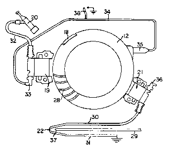
An embodiment of the invention is described below with
reference to the accompanying drawing in which Figure 1
schematically shows a heating device according to the invention.
Figure 2 shows schematically the ignition system.
The shown heating device comprises a combustion engine
11 provided with a flywheel 12 and an outgoing shaft 23. Shaft 23
drives a fan 13 and an oil pump 16. Oil pump 16 sucks oil through
a tube 24 from a tank 25 and delivers the oil through a tube 29 to
a nozzle 37 in an oil burner 15 where the oil is atomized.
Flywheel 12 is provided with means, ln the form of a
magnet 18, for lnitiating an ignition pulse in each ignition coil
19, 21. The ignition coils are of normal, commerclally available,
~.,

~7~54
27898-1
type which comprise a sensing coil and semiconductors for voltage
amplification and possibly pulse shaping. The unit 19 delivers
ignition pulses via conductor 32 to spark plug 20 of the
combustion engine. Unit 21 delivers ignitlon pulses via conductor
30 to a spark gap 22 where the atomized oil is ignited. Conductor
31 connects the spark gap 22 to common. Flywheel 12 is provided
with fan blades 28 of which only a few are shown. Unit 19 is
provided with a short circuit device 33 to which a conductor 34
and one or more sensing units 38, in the form of bimetal springs,
are connected between the normal stop button 35 and the short
circuit device 33 on the ignition coil 19. Unit 38 can be
arranged to sense overheating of for instance the heat exchanger
in which case the short circuit device 33 short circuits the
ignition coil 19 so that no ignition pulses reach the spark plug
20. Spark plug 21 can be short-circuited in a similar way by
means of the short circuit device 36.
Fan 13 supplies fresh air to chamber 14 where the air is
heated through heat exchanging contact with the outlet channel 17
of oil burner 15. Combustion gases from the oil burner are
conducted away through an exhaust pipe 26. The heated air is
conducted through the outlet 27 to a consumer which could be a
tent or similar or another space which is to be heated.

Representative Drawing
A single figure which represents the drawing illustrating the invention.
Administrative Status

2024-08-01:As part of the Next Generation Patents (NGP) transition, the Canadian Patents Database (CPD) now contains a more detailed Event History, which replicates the Event Log of our new back-office solution.

Please note that "Inactive:" events refers to events no longer in use in our new back-office solution.

For a clearer understanding of the status of the application/patent presented on this page, the site Disclaimer , as well as the definitions for Patent , Event History , Maintenance Fee  and Payment History  should be consulted.

Event History

Description Date
Inactive: IPC from MCD 2006-03-11
Inactive: Adhoc Request Documented 1994-01-22
Time Limit for Reversal Expired 1993-07-24
Letter Sent 1993-01-22
Grant by Issuance 1991-01-22

Abandonment History

There is no abandonment history.

Owners on Record

Note: Records showing the ownership history in alphabetical order.

Current Owners on Record
ATLAS COPCO AKTIEBOLAG
Past Owners on Record
BO BAYARD
Past Owners that do not appear in the "Owners on Record" listing will appear in other documentation within the application.
Documents

To view selected files, please enter reCAPTCHA code :


To view images, click a link in the Document Description column. To download the documents, select one or more checkboxes in the first column and then click the "Download Selected in PDF format (Zip Archive)" or the "Download Selected as Single PDF" button.

List of published and non-published patent-specific documents on the CPD .

If you have any difficulty accessing content, you can call the Client Service Centre at 1-866-997-1936 or send them an e-mail at CIPO Client Service Centre.


Document
Description 
Date
(yyyy-mm-dd) 
Number of pages   Size of Image (KB) 
Cover Page 1993-10-18 1 9
Abstract 1993-10-18 1 7
Drawings 1993-10-18 1 15
Claims 1993-10-18 2 47
Descriptions 1993-10-18 3 91
Representative drawing 2001-12-31 1 10