Language selection

Search

Patent 1279489 Summary

Third-party information liability

Some of the information on this Web page has been provided by external sources. The Government of Canada is not responsible for the accuracy, reliability or currency of the information supplied by external sources. Users wishing to rely upon this information should consult directly with the source of the information. Content provided by external sources is not subject to official languages, privacy and accessibility requirements.

Claims and Abstract availability

Any discrepancies in the text and image of the Claims and Abstract are due to differing posting times. Text of the Claims and Abstract are posted:

  • At the time the application is open to public inspection;
  • At the time of issue of the patent (grant).
(12) Patent: (11) CA 1279489
(21) Application Number: 1279489
(54) English Title: SNOW GUN
(54) French Title: CANON A NEIGE
Status: Expired and beyond the Period of Reversal
Bibliographic Data
(51) International Patent Classification (IPC):
  • F25C 03/04 (2006.01)
  • B05B 07/04 (2006.01)
(72) Inventors :
  • STANCHAK, YAROSLAV I. (United States of America)
  • MAKKONEN, NIILO J. (United States of America)
  • WARYAS, VICTOR (United States of America)
(73) Owners :
  • KILLINGTON LTD.
(71) Applicants :
  • KILLINGTON LTD. (United States of America)
(74) Agent: NORTON ROSE FULBRIGHT CANADA LLP/S.E.N.C.R.L., S.R.L.
(74) Associate agent:
(45) Issued: 1991-01-29
(22) Filed Date: 1987-04-30
Availability of licence: N/A
Dedicated to the Public: N/A
(25) Language of filing: English

Patent Cooperation Treaty (PCT): No

(30) Application Priority Data:
Application No. Country/Territory Date
933,227 (United States of America) 1986-11-26

Abstracts

English Abstract


SNOW GUN
ABSTRACT OF DISCLOSURE
A nozzle structure for mixing high pressure
water with compressed air has an adjustable size coni-
cally shaped water opening that permits a conical sheet
of water to form the air nozzle adjacent the nozzle's
exit end.


Claims

Note: Claims are shown in the official language in which they were submitted.

WE CLAIM:
1. In a system for making snow from compressed air and
water, an improved nozzle structure comprising means
defining a longitudinally extending air passageway with a
generally cylindrical inlet end portion adapted for
connection with a source of air under pressure,
said air passageway defining means including a cap
defining an outlet end portion of said air passageway of
smaller cross sectional area than that of said inlet end
portion,
said air passageway defining means further including
a convergent air nozzle member intermediate said inlet
and outlet end portions,
said cap defined outlet end portion of said air
passageway having a conical configuration that continues
the convergent shape of said air nozzle member,
means for locating/positioning said outlet defining
cap longitudinally relative to said convergent air nozzle
member to provide an opening between an upstream end of
said outlet defining cap and a downstream end of said
convergent nozzle member, and
outer housing means defining a water plenum chamber
communicating with said opening and adapted for
communication with a source of water under pressure to
restrict the effective area of the outlet end portion of
said air passageway defined by said cap so that the
air/water mixture can be closely controlled to optimize

performance of the air/water nozzle structure in a wide
variety of ambient temperature and humidity conditions.
2. The combination of claim 1 wherein said convergent
nozzle member comprises a body of revolution defining a
conically shaped convergent axial segment of said air
passageway.
3. The combination of claim 2 wherein said housing
means comprises a hollow cylindrical body member having a
threaded portion that defines in part said means for so
locating said cap relative to said nozzle member.
4. The combination of claim 3 wherein said opening has
an annular shape such that the water enters said air
passageway in the shape of a conical sheet.
5. The combination of claim 4 wherein said annular
shape of said opening is more particularly that of a
conical segment forming an entry angle with the
longitudinal axis of the air passageway in the range
between 20-60 degrees.
6. The combination of claim 3 wherein said cap has a
threaded portion that threadably engages said threaded
portion of said cylindrical body member to provide said
longitudinal positioning of said cap relative said nozzle
member.

7. The combination of claim 6 wherein said opening has
an annular shape such that the water enters said air
passageway in the shape of a conical sheet.
8. The combination of claim 7 wherein said annular
shape of said opening is more particularly that of a
conical segment forming an entry angle with the
longitudinal axis of the air passageway in the range
between 20-60 degrees.
9. The combination of claim 8 wherein said cap defined
outlet end portion of said air passageway has a conical
configuration that is no greater in cross sectional size
than the downstream end of said nozzle member.
10. The combination of claim 9 wherein the inlet end of
said convergent air passageway defined by said nozzle
member and the exit end of said cap have an area ratio of
approximately 4:1.
11. The combination of claim 1 further characterized by
a source of water under pressure, said water pressure
being provided in a range between 250-400 pounds per
square inch to said plenum chamber.
12. The combination of claim 11 wherein said convergent
nozzle member comprises a body of revolution defining a
conically shaped convergent axial segment of said air
passageway.

13. The combination of claim 12 wherein said cap has a
threaded portion that threadably engages said threaded
portion of said cylindrical body member to provide said
longitudinal positioning of said cap relative said nozzle
member.
14. The combination of claim 13 wherein said opening has
an annular shape such that the water enters said air
passageway in the shape of a conical sheet.
15. The combination of claim 14 wherein said annular
shape of said opening is more particularly that of a
conical segment forming an entry angle with the
longitudinal axis of the air passageway in the range
between 20-60 degrees.
16. The combination of claim 15 wherein said convergent
air passageway defined by said nozzle member and the exit
end of said cap have an area ratio of approximately 4:1.

Description

Note: Descriptions are shown in the official language in which they were submitted.


~.~7~
--l--
SNOW GUN
This invention relates generally to nozzle
structures for producing snow from a mixture of water and
air supplied to the nozzle under pressure. More parti-
cularly, the present invention relates to an improved
nozzle structure which is provided with water under re-
latively high pressure, and which is designed to utilize
the water to define the air nozzle itself so that less
compressed air is required to produce the moisture laden
spray of small uniformly sized water particles ejected
from the nozzle structure into the ambient air than has
been possible with prior art snow guns.
The nozzle structure in its presently preferred
form includes a convergent nozzle member having an inlet
end adapted for connection to a source of air under pres-
sure and having an outlet that cooperates with a nozzle
cap that is adjustably positioned axially relative to the
nozzle member to define an inclined conically shaped
water opening between the upstrea~ end of the cap and the
downstream end of the nozzle member. The cap has an exit
end of cross sectional area significantly less than the
cross sectional area of the inlet end of the noæzle
member, and this area ratio is preferably on the order of
4 to 1. Water pressure provided to an annularly shaped
plenum chamber defined between the nozzle member and an
outer housing or body is preferably in the range between
250 to 400 pounds per square inch gage. Air pressure is
made available to the nozzle at approximately 50 - 100

--2--
pounds per square inch and the geometry is such that
increasin~ water flows at pressures in this range can
achieve reduced air flows and the econo~ies achieved are
quite significant because of the expense involved in
providing compressed air as opposed to providing water
under pressure to snow nozzles in a large snow making
system of the type employed at present day major ski
areas.
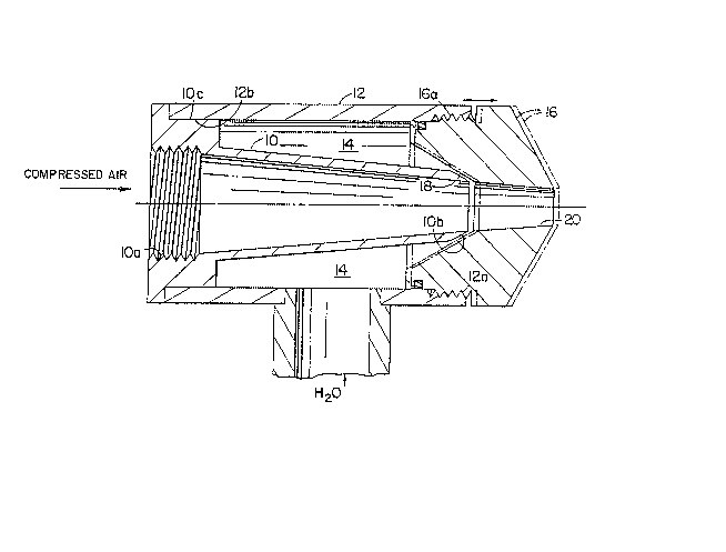
Fig. 1 is a cross sectional view of the nozzle
structure of a perferred form of the present invention-
Fig. 2 presents graphically the variationachieved in water and air flows with variations in the
size of the annular conically shaped opening provided for
the water inside the nozzle structure i~self at constant
supply pressure for air and water.
Fig. 3 shows the variation in air flow with
increasing water pressure and flow at a particular water
gap opening. Smaller water gaps will provide higher air
flows and the general relationships can be seen in the
family of curves presented.
Turning now to the drawings in greater detail, a
preferred form of snow gun is illustrated in Fig. 1 as
including an air nozzle defining member lO that is pre-
ferably in the form of a body of revolution and which
defines a longitudinally extending air passageway having
a generally cylindrical inlet end portion lOa that is
adapted for connection with a source of air un~er pres-
sure. The nozzle member has a downstream end lOb that

-3~
is inclined with respect ot the longitudinal axis of its
convergen~ central air passageway.
The air passageway is further defined by a cap
16 which cap defines an outlet end portion 20 of the air
passageway that has an exit end of smaller cross section-
al area than that of the above mentioned inlet end por-
tion lOa of the nozzle member 10. The cap 16 further
includes a generally conically shaped surface 18 at its
upstream end that is inclined relative to the longitu
dinal axis of the nozzle structure at an angle in the
range between 20 and 60 degrees, and preferably in the
range between 30 and 45 degrees.
Means is provided for aajustably locating or
positioning the outlet defining cap 16 relative to the
convergent air nozzle member 10 in order to provide an
opening between the downstream end lOb of the nozzle
member 10 and the upstream end 18 of the cap 16. Pre
ferably, said means for so adjusting said cap relative
said n~zzle member comprises an outer housing means of
body 12 that also serves to define the annularly shaped
water plenum chamber between it and the exterior of the
nozzle member 10. Such plenum is indicated generally at
14 and is adapted to be connected to a source of water
under relatively high pressure preferably in the range
between 250 and 400 pounds per square inch gage. This
outer housing means 12 includes a downstream portion that
has an internal or female thread 12a adapted to thread-
ably receive the portion 16a of the cap which is exter-
, ' '
' ~

nally threaded and to provide for axial adjustment of thecap relative the nozzle member to achieve a predetermined
spacing between the surfaces 18 and lOb of th~ cap and
nozzle member respectively.
The upstream end portion of the housing or body
12 is preferably secured to the upstream end of the
nozzle member 10 as indicated generally by the mating
surfaces 12h and lOc of the body 12 and thc nozæle member
10 respectively. The outer housing of body 12 is also
preferably shaped in the form of a body of revolution in
order to provide a generally cylindrical exterior for the
snow gun and this body 12 includes a port of conventional
configuration to receive a fitting (not shown) to facili-
tate attachment to the water conduit (also not shown)
that provides the high pressure water to the plenum
chamber 14 as mentioned previously.
As so constructed and arranged the nozzle struc-
ture is designed to form an annular sheet or cone of
water delivered under pressure of at least 250 pounds
per square inch gage and preferably on the order of 350
pounds per square inch gage to create a "water" nozzle
for the air such that the air flow tends to re~ain rela-
tively constant once this water pressure is reached.
This is true even i the water pressure be further
increased above 350 pounds per square inch gage in order
to further increase the water flow. Figure 2 illustrates
the calibration curves for the water and air in a gun
that ha~ been connected to a source of water under pres-

--5--sure of 350 pounds per square inch gage and to a source
of compressed air under pressure of 75 pounds per square
inch. The calibration curve of Fig. 2 illustrates the
fact that variations in the axial position of the cap
relative to the nozzle member (that is varying the size
of the water opening) leads to predictable changes in the
gallons per minute of water. This is illustrated by the
straight line relationship for the water flow in this
view. Fig. 3 shows how the air flow can be reduced at a
particular water gab opening simply by increasing water
pressure, and hence water flow in gallons per minute.
The snow gun described and claimed herein pro-
vides a convenient structure for achieving predictable
water and air flow mixtures in the hostile environment of
winter ski slopes, and once such a gun has been properly
adjusted it can be used to make snow at a specific water
operating pressure and thereby efficiently control the
quantity of air consumed in a manner that is vastl~ sup-
erior to that afforded by present day snow guns gen-
erally. The capability for fine tuning and adjusting
the water/air mi~ture leads to more predictable resultsunder predetermined atmospheric conditions. For example,
and referring to the settings illustrated on the base
line of Fig. 2, at temperatures slightly below freezing
nozzles with a setting of 1 afford favorable air consump-
tion rates in a system which never~heless is capable oE
efficient snow maXing. Moreover, when the temperat~res
drop to the range of -5 to -20 degrees Celsius higher
.

-6- ~7~
settings can be used affording the ski slope operator
with the ,opportunity to make more snow than would be the
case if the same gun should be used, that is, as clefined
by a snow gun with a sett~ing of 1. In short, the ski
slope operator can pre-set a number of guns ~o permit use
of such guns under a wide variety of ambient conditions
and thereby make snow with maximum efficiency (defined
as minimal use of compressed air and maximum quantity
of snow made~ simply by reverting to the proper setting
on the calibrated gun itself with preference to the data
described above relating ambient temperature and humidity
conditions to settings for the nozzle cap relative the
fixed nozzle structure all as described above.
In practice a water gap between the nozæle
member and cap is in the range of 0.020 inches to 0.200
inches has been found to provide satisfactory snow making
in a nozzle having an exit end of approximately one inch
or less in diameter.
The longitudinally extending air passageway defined
by the convergent air nozzle member and the cap which
is provided in longitudinally adjustable relationship
thereto cooperate to define a passageway that is contin-
uously convergent from the inlet to the exit end portion
thereof.
A

Representative Drawing
A single figure which represents the drawing illustrating the invention.
Administrative Status

2024-08-01:As part of the Next Generation Patents (NGP) transition, the Canadian Patents Database (CPD) now contains a more detailed Event History, which replicates the Event Log of our new back-office solution.

Please note that "Inactive:" events refers to events no longer in use in our new back-office solution.

For a clearer understanding of the status of the application/patent presented on this page, the site Disclaimer , as well as the definitions for Patent , Event History , Maintenance Fee  and Payment History  should be consulted.

Event History

Description Date
Inactive: IPC from MCD 2006-03-11
Time Limit for Reversal Expired 1998-01-29
Letter Sent 1997-01-29
Grant by Issuance 1991-01-29

Abandonment History

There is no abandonment history.

Owners on Record

Note: Records showing the ownership history in alphabetical order.

Current Owners on Record
KILLINGTON LTD.
Past Owners on Record
NIILO J. MAKKONEN
VICTOR WARYAS
YAROSLAV I. STANCHAK
Past Owners that do not appear in the "Owners on Record" listing will appear in other documentation within the application.
Documents

To view selected files, please enter reCAPTCHA code :


To view images, click a link in the Document Description column. To download the documents, select one or more checkboxes in the first column and then click the "Download Selected in PDF format (Zip Archive)" or the "Download Selected as Single PDF" button.

List of published and non-published patent-specific documents on the CPD .

If you have any difficulty accessing content, you can call the Client Service Centre at 1-866-997-1936 or send them an e-mail at CIPO Client Service Centre.


Document
Description 
Date
(yyyy-mm-dd) 
Number of pages   Size of Image (KB) 
Abstract 1993-10-14 1 10
Drawings 1993-10-14 3 54
Claims 1993-10-14 4 110
Descriptions 1993-10-14 6 198
Representative drawing 2001-07-10 1 19
Fees 1996-06-27 1 54
Fees 1993-12-08 1 104
Fees 1995-03-20 1 47
Fees 1993-01-12 1 45