Note: Descriptions are shown in the official language in which they were submitted.
~279~;49
- 1 -
VENTILATORS AND PRESSURE OSClLLATORS THEREFOR
The present invention relates to ventilators for
the artif;cial or assisted respiration of patients,
05 and to pressure oscillators being ComPonents of such
ventilators~
Adult and paediatric patients ~ho are maintained
by a regime of positive pressure ventilation are
likely to develop various complicating conditions
related to the use of this type of ventilation. These
include barotrauma of various kinds such as
pneumothorax, pneumomediastinum, pneumopericardium,
pneumoperitoneum, subcutaneous emphysema and air
embolization.
The act of intubation itself presents hazards in ven-
tilation including disconnection, inadvertent extubation,
tracheal trauma, infection, tube blockage, vocal cord dys-
function and subglottic stenosis. Intubation also is a
highly skilled procedure.
Negative pressure ventilators of the "iron lung"
and iron cuirass" type for adult patients and
children have long been available and ~ere the first
type of ventilators to be developed. These functioned
~ell for pat;ents such as those affected by
poliomyelitis and other neuro-muscular disorders ~here
the lungs are essentially healthy but their function
is disrupted by impairment of neurologic function,
muscle con~raction etc. They ~ere much less
successful in conditions such as adult respiratory
2 1Z79S49
d;stress syndrome (ARDS) where the Lungs themselves
contain the primary defects includ~ng reductions ;n
pulmonary compliance and increased air~ay resistance.
They have accordingly very largely fallen out of use
05 in tavour ot a variety ot positive pressure
ventilation regimes despite the problems attendant
upon the use ot positive pressure.
Generally, such negative pressure ventilators
operate at a low trequency such as 10 to 20 breathing
cycles per minute. In the negative pressure cuirass
type ventilator described in US-A-3,078,842, a
pressure alternator provides pressure variations at a
trequency ot 10 to 20 per minute to produce
ventitation, whilst a second pressure alternator
superimposes periodica~y a very high pressure at a
higher trequency (60 to 120 pulses per minute) to
produce cardiac massage. This device is intended tor
resuscitation trom pulmonary and cardiac arrest and
not tor prolonged ventilation. The high trequency,
high pressure aspect ot the treatment is to stimulate
the heart and is not suitable in itself to produce
ventilation.
Particular d1tticulties arise in the ventilation
ot neonate and preterm babies~
Neonate and preterm babies with respiratory
ta1lure develop hypoxia, and metabolic and respiratorY
acidosis that may lead to their death it untreated bY
assistant ventilation.
1279549
At present, neonates needing to be ventilated are
generally intubated and respiration is then forced by
positive pressure applied to the lung through the
lntubation. This procedure carries with it a serious
05 risk ot barotrauma as described above, in particular,
pneumothorax, pneumomediastinum, interstitial
emphysema, or ~ronchopulmonary displasia (BPD). A
very high proportion ot babies ventilated by this
method, known as intermittent positive pressure
ventilation (IPPVj, will develop BPD caused directly
by this procedure. There is also a danger ot causing
laryngiaL and tracheal complications and ot
introducing intection into the lung.
As many as titteen percent ot babies ventilate~
by IPPV have the complication ot interstitial
emphysema which carries a h1gh mortality rate.
The IPPV procedure has however been found
preterable in many circumstances to the use of
ventilators ot the kind described tor instance in
United States patent specitication 2863447 which is a
negative pressure ve n tilator having an incubator
torming a pressure chamber divided into two
compartments by a tlexible seal. The head ot the
intant is contained in one compartment and the body ln
the other and the seal makes a substantially gas tight
seal about the intants neck. It is then possible to
1~79549
produce a cycLic variation of pressure in the body
compartment and optionally aLso the head compartment.
Partia~ evacuation of the body compartment ~ith or
wlthout simultaneous increase ot pressure in the head
05 compartment causes expansion ot the lungs and re~ease
ot air into the body compartment alLows the Lungs to
expeLl air. GeneraLly, such negative pressure
ventilators operate at a rate ot trom 20 to 60 cycLes
per minute.
Such negative pressure ventiLators have been
tound to have several severe drawbacks some ot ~hich
reLate to the structure ot the incubator.
First, it is almost impossibLe to use such
ventiLators to ventiLate babies having a weight ot
less than 1.5 kilograms. The pressure ditterential
between the atmosphere surrounding the head and the
interior ot the ~ody compartment produces torces
trying to suck the babies head through the tlexible
sea~ and this imposes an excessive strain on the
babies neck in the case ot very smaLL babies.
Secondly, the patient is inaccessible tor routine
or emergency procedures. Being entireLy contained
within the ventilator which must be kept closed if
ventilation is to continue, the patient is wholly
lnaccessible. for instaLling or maintaining drips or
arterial lines and even tor simp~e operations such as
.. ..
1~795~9
cleaning and nappy changing, the ventilator must be
opened and the patient must be intubated.
Third~y, the operation ot the ventiLator produces
a constant tlow ot alr into and out of the body cavity
05 ot the ventilator which produces a cooLing eftect
which is difticult to counteract. Very small babies
are ot course very prone to sufter severe heat loss.
Negative pressure ventilators ot this kind
proposed in the past are relatively expensive because
they involve an entire incubator.
Most seriously however, negative pressure
ventilators ot previously known designs do not provide
maintain clinical parameters at acceptable values in
actual use in treating patients with lung disorders
and they have not tound clinical acceptance. Despite
the known prob~ems, IPPV techniques are still the
mainstay ot clinical practice in this tield.
Unitled States Specitication US-A-3,903,869,
(Bancalari) disc~ose a continuous negative pressure
chamber tor treating intants ~ith ideopathic
respiratory distress syndrome (IRDS). The chamber
receives the trunk ot an intant, seals being provided
at the neck and abdomen~
The chamber ot US-A-3,903,869 is not in tact
intended to produce torced respiration but rather to
assist spontaneous breathing. In some embodiments, it
. . . .
~Z~9~;4g
provides a constant negative pressure to prevent Lung
collapse. In the embodiment described ~ith reference
to Figure 4, provision is made for increasing negative
pressure cyclically at up to 30 to 40 cycles per
S minute to induce spontaneous breathing by stirring the
infant out of apnea.
WhiLst both positive pressure and negative
pressure ventilation have traditionally operated at
frequencies simiLar to those of natural breathing,
more recently techniques of high frequency positive
pressure ventilation (HFPPV) have been proposed,
although not ~idely accepted. In such methods,
ventilation is conducted at above 1Hz. It was hoped
that the small tidal volumes and generally lower
airway pressures developed by high frequency
ventilators would be associated with a lower incidence
of complications, but experience has not borne this
out. Interest in this technique was widespread for a
brief period but is now decreased.
Little is known about the mechanisms by which
oxygenation and ventilation occur during HFPPV
although a number of plausible theories have been
proposed.
Some experimental ~ork on healthy animaLs and
healthy animal lung tissue has been conducted using
brief periods of external high frequency.
1279$~9
ventilation, but until now there has been no demonstra-
tion of a technique of this type capable of providing satis-
factory ventilation for prolonged periods of healthy
lungs nor of a sick lung.
05 Ward et al (J. Appl. Physiol: Respirat. Environ.
Exercise Physiol. 54 (2):427-433, 1983) applied external
high frequency oscillatory ventilation to isolated, per-
fused rat lung and concluded that satisfactory oxygen
uptake could be maintained by this method.
Harf et al (J.Appl.Physiol: Respirat. Environ.
Exercise Physiol. 56 (1): 155-160, lg84) compared external
and internal (tracheal) high frequency ventilation for five
minutes in rats with normal lungs and found them equally
effective.
In the development of the present invention, however,
it has been found that in the application of the method
employed by Harf et al to cats with normal lungs, there was
severe progressive fall in functional residual capacity
(FRC) which produced also a reduction in blood oxygen
tension. Cats whose lungs have been rendered stiff by
lavage with saline as a model of sick lung could not
be successfully ventilated in this way nor even cats with
normal lungs for a period more than a few minutes.
The present invention seeks to overcome the problems
described above by providing methods and
127~ 9
apparatus suitable for the satisfactory negative
external ventilation of sick lungs, thus avoiding the
complications associated with positive pressure
ventilating systems.
It has been discovered that in an external
high frequency ventilator, the use of a negative base
line chamber pressure provides strikingly improved
results. Further, it has been found that improved
results also follow from the use of pumped displacement
of gas into the chamber surrounding the chest during the
pressure rise part of the cycle rather than relying on
release of air into the chamber from atmosphere.
Accordingly, in one aspect, the present
invention provides a ventilator for producing artificial
respiration comprising a pressure chamber for receiving
at least the chest of a patient so as to establish a
volume exterior of the chest between which volume and
the lungs of the patient a pressure differential may be
produced by pressure changes applied to the pressure
chamber: means for establishing a sub-ambient pressure
in the pressure chamber; and means for varying the
pressure in the chamber, so as to superimpose on the
sub-ambient pressure a cyclic variation having a
frequency of above 1 Hz.
Preferably, the means for establishing a
sub-ambient pressure in said chamber is adapted to
produce a negative pressure of at least 19~ Pa (2 cm
-
lZ79549
H2O), e.g. from -196 to -2940 Pa (30 cm H2O), more
preferably from -196 Pa (2 cm H2O) to -1961 Pa (20 cm
H20) .
Preferably, the means for establishing a
sub-ambient pressure in said chamber is adjustable to
provide a desired sub-ambient pressure and as the most
preferred mean chamber pressure is about -980 Pa (-10 cm
H2O), preferably at least a range of from -490 Pa (5 cm
H2O) to -1470 Pa (15 cm H2O) is available.
Preferably, the means for varying the pressure
in the chamber is adapted to produce a pressure
variation amplitude of from 392 Pa (4 cm H20) to 3136
(32 cm H2O).
Preferably, the means for varying the pressure
in the chamber is adjustable to produce a desired
amplitude of pressure variation such as from 785 Pa (8
cm H2O) to 1570 Pa (16 cm H20).
Preferably, the means for varying the pressure
in the chamber is adjustable to provide a desired shape
of wavefonn for said cyclic pressure variation. It may
for instance be possible to vary the I/E ratio, to
choose between two or more of a sine wave pattern, a
square wave pattern or a saw tooth wave pattern for the
whole of the pressure variation, or for parts of
"".`1 '.
~279549
- 10 -
the wave form or to choose other wave forms.
It may be convenient for said means for
establishing a sub-ambient pressure in said chamber,
and means tor varYlng the pressure in said chamber so
05 as to superimpose on said sub-ambient pressure a
cyclic variation having a frequency ot above 1 kz to
be provlded ln combination by a pump unit.
Preterably, said pump unit comprises a piston
member tor driving a volume ot air cyclicly into and
out said chamber to produce said pressure variation,
and valve means positioned and adapted to vent a
proportion ot the air displaced by said piston member
out ot the ventilator to establish said sub-ambient
pressure in the chamber.
Said piston member may be a flexible diaphragm
secured around an edge region thereof to close a pump
chamber and having a central region which is
reciprocable to pump air to and trom pump chamber,
said pump chamber communicating ~ith said pressure
~0 chamber.
Said valve means may be a non-return valve
allowing limited air tlow out of said pressure
chamber.
Preterably, said means tor varYing the pressure
in sai~ chamber comprises a motor operating a pump
unit, uhich motor is a variable speed motor.
12~9549
- 11 -
Preferably, said variable speed motor is a
stepping motor. By teeding suitable patterns ot
stepping pulses to the motor, any desired waveform of
pressure variation may then be obtained and both shape
05 and trequency ot the waveform may be varied at will.
Preterably, said piston member is reciprocable
along a tirst axis, a motor is provided having an
output shatt rotating about a second axis parallel to
the tirst axis, a radius member is provided extending
radia~ly ot the output shaft and connected to rotate
therewith about the tirst axis, and a link is provided
between the piston member and the radius member.
Suitably, the means for varying the pressure in
the chamber is adapted to produce cyclic variations in
said pressure at a trequency ot trom 3 to 12 Hz.
The trequencies most advantageously used are trom
4 to 8 Hz, eg. about 5 Hz.
Pret,erably, the pressure chamber has a pair of
opposed wa~l portions mutua~ly spaced by an amount
suitab~e to accomodate between them the chest portion
ot the trunk ot an intant and means detining an inlet
and outlet tor gas to and trom said chamber, each said
wa~ portion containing an aperture for receiving a
portion ot the trunk ot the infant, and means being
associated with each such aperture tor producing an at
least substantially gas tight seal bet~een the
respective wall portion and the patient's trunk in
127954~
- 12 -
use.
A patient may be placed in such a ventilator so
that the ventilator extends only from the axiLla at
the one end to the lower abdomen or pelvis at the
05 other, so that only the chest and abdomen are inside
the chamber. This avoids the strain upon the neck
encountered in small intants when using a conventional
negative pressure ventilator. Cyclic pressure changes
may be 1nduced in the chamber through the gas inlet
and outlet in a manner similar to that employed in
conventional negative pressure ventilators.
The ventiLator may comprise means defining a
separate inlet tor gas to the chamber and a separate
outlet tor gas trom the chamber but it is preterred
that the pressure oscillations be produced by pumping
gas in and out ot the chamber alternately through a
common tLow path.
PreterabLy, the chamber is provided with an
acçess door intermediate said opposed wa~l portions by
means ot which a patient may be inserted into the
chamber. Alternatively however~ the patient may be
inserted through the apertures in the opposed wall
portions.
Preterably the means tor producing a seal to the
trunk each comprise a variable aperture diaphragm.
This may tor instance be of the kind described in
9~4L9
13
United States Patent No. 2,863,447 or of any other kind
heretofore used in negative pressure ventilators for a
similar purpose.
The present invention includes a method of
assisted respiration of a patient eg. an infant patient,
comprising producing between the chest of the patient
and the trachea of the patient a cyclically varying
pressure differential at a frequency of at least 1 Hz,
more preferably from 3 to 12 Hz, for instance 4 to ~ Hz,
about a negative mean by varying the pressure outside
the chest of the patient.
The present invention also includes a method
of assisted ventilation of a patient comprising placing
at least the trunk of a patient within the pressure
chamber of a ventilator as described herein, and
applying said cyclic pressure changes to the pressure
chamber to assist respiration.
The invention includes an oscillator unit for
producing cyclic pressure variations about a sub-ambient
ZO base line pressure comprising means for establishing a
gas flow connection from the oscillator to a patient
receiving pressure chamber, means for pumping air from
the pressure chamber to produce a negative pressure
therein, and means for pumping air to and from the
pressure chamber cyclically at a frequency
. ~ . ~ ,,
~Z79549
- 14 -
of at least 1 Hz.
Whilst the preferred means ot producing cyclic
pressure changes in the chamber ot a ventilator as
described above is to attach to the gas connection or
05 connections thereot a source of varying gas pressure
operating to produce pressure changes in the chamber
by inflow and outtLow of gas, alternative means of
producing pressure changes in a chamber ot a
ventilator are available and may be used.
Such a means for producing cyclic variation maY
tor lnstance be a tlexible wall member defining the
chamber volume together with means tor moving the
tlexible wa~l member between positions in which the
volume ot the chamber if greater and lesser
respectively. By such a mechanism, the cyclic inflow
and outtlow ot gas trom the chamber can be avoided. A
base line negative pressure may be provided by a
constant source of vaccuum such as a constant speed
vaccuum pump.
The invention will be ;llustrated by the
following description of a preferred embodiment
thereof with reference to the accompanying drawing
which:-
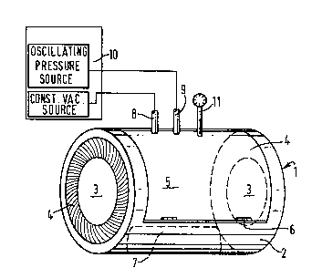
Figure 1 shows in schematic perspective view a
ventilator according to the invention, and
Figure 2 shows schematically an alternative
1~79S~9
oscillating pressure source for use with the chamber
of Figure 1.
As shown in Figure 1, ventilating apparatus 1
comprises a chamber 2 in the form of a cylindrical
05 chamber having at each end an aperture 3 defined by a
radially expansible diaphragm 4.
An access door 5 is mounted on hinges 6 and opens
about a hinge axis extending parallel to the axis o~
the cylinder. The door is provided with a suitable
latch means for retaining it closed and with suitable
seals about its periphery to maintain the chamber
sealed when the door is shut. A pillow as shown at
7 may be positioned w;thin the ventilator to support
the trunk of an ;nfant patient.
The chamber is prov1ded with two gas connections
8, 9 for connection to an oscillating pressure source
schematically indicated at 10. A pressure gauge 11 is
provided to enable monitoring of the gas pressures in
the chamber.
The entire chamber 2 can be placed within a
conventional incubator and the oscillating pressure
source can be arranged to draw and exhaust its air
used for pressurising and depressurising the chamber
2 from the inter;or of the incubator. By this means,
the severe cooling effects found in using negative
pressure ventilators in the past may be avoided.
-
~;~79S~9
~ 16 -
If desired, the distance between the two
diaphragms 4 may be made adjustable to enable
different sizes of infant to be accomodated. However,
this will not generally be necessary. The leftmost
05 diaphragm is intended to be located around the axilla
ot the intant patient and the rightmost diaphragm maY
be Located at any position between the lower end of
the rib cage and the pelvis.
One suitable method of producing the expansible
diaphragm 4 is described in United States
specitication No. 2863447. Such a diaphragm comprises
a pair ot mutually rotatable circular rim members
- spaced by a short distance along the axis of the
cyLinder 1. A soft flexi~le tube of plastics or
rubber material is connected at one end to a first ot
the rim members and at the other end to a second of
the rim members. The rim members are mounted in a
mutually rotatable manner. Rotation ot the rim
members with respect to one another produces tolds and
pleats in the sott tube ~hich constrict the diameter
ot the tube and torm a tlexible and comfortable seal
about the body of the infant occupying the chamber. A
seal of this type may be used at each end ot the
ventilator.
The oscillating pressure source 10 maY
:`'"
1~79549
- 17 -
comprise a source of constant negative pressure
connected to gas connection 8 of the chamber ~hereby a
bac~ground negative presssure is established in the
chamber at a desired ~eveL togetner ~itn a source ot
05 oscilLating pressure such as a piston pump adapted to
pump a constant volume ot gas back~ards and for~ards
into and out ot the chamber connected through the
other connection 9 ot the chamber.
Preterably, both the source ot constant negative
pressure connected at connection 8 and the oscillating
pressure source connected at connection 9 are
adjustable so that the mean chamber pressure, the span
ot the pressure variation about the mean and the
trequency are a~l selectab~e by the user.
An alternative form of oscillating pressure
source is sho~n in Figure 2. This is adapted to
produce through a single connection both a negative
mean chamber pressure and the required oscillation of
the pressure. Accordingly, in using the oscillating
pressure source ot Figure 2, one ot the connections 8,
9 ot the chamber will be blanked off.
The oscillating pressure source sho~n in Figure 2
comprises a pump unit comprising a pressure chamber 20
having a tront wall 21 and an annular side ~a~l 22
with a tlexibLe diaPhragm 23 closing the rear of the
pressure chamber to define a generally cylindrical
1;27~
- 18 -
volume within the pressure chamber which is variable
by axial displacement ot the diaphragm 23. A gas
outl~t Z4 lS provided in the front wall 21 for
connection to the chamber.
05 A valve port 25 is tormed in the annular ~all 22
; an~ ls coverea ~y a valve tlap 26 hinged tor outward
movement to the position shown dotted. Valv~ flap 26
is resiliently biassecl to the closed position by means
not shown~ Suitably the biassing of flap 26 is
simply by virtue ot its own naturaL resilience.
A lin~ shatt 27 is connected to the centre ot
diaphragm 23 by a un;versal joint 28. At its other
end link shaft 27 is connected through a universal
joint 29 to an eccentric position on a disc 30 which
is mounted for rotation by a stepping motor 31 at its
axis. Disc 30 serves as a rad;us member mounting one
end of link 27 for rotation eccentrically about the
axis of the motor 31.
As sho~n in the ~igure the diaphragm 23 is
axially displaceable by rotation of the disc 30 by the
motor 31. The position adopted by the diaphragm and
the link 27 at an opposite extreme part of the
::
rotational cycle is sho~n by dotted lines in the
figure.
Rotation of the motor 31 produces reciprocating
; ~ ; movement of the diaphragm 23 acting as a piston member
,
1279549
to displace gas backwards and forwards through the
connection 24.
As the diaphragm 23 moves to compress in the
pressure chamber 20 and to displace gas out of the
S connection 24, the valve flap 26 opens and some gas ;s
lost from the pressure chamber 20 through the valve
port 25~ Valve flap 26 closes to prevent re- entry of
gas from the exterior when the diaphragm 23 is
~ithdrawn by the motor 3l. Thus, although gas is
pumped to and fro through connection 24, some gas is
continuously lost from the system generating a
negative base line pressure. Of course, gas also
enters the chamber through any leak present in the
seals so mitigating the negative pressure produced by
the action of the valve 25,Z6.
The motor 31 is a stepping motor and ;s driven by
the provision of suitable stepping pulses. These may
be produced by suitable microprocessor circuitry and
sequencies of pulses may be sent to the motor to
produce any desired variation in speed within a single
revolut;on. Thus, the pressure ~ave form produced at
the connect;on 24 may be closely controlled by the
provis;on of suitable control circuitry and the user
may be provided with the means to shape the ~ave form
as he desires as ~ell as to choose the frequency of
the pressure oscillation, the mean chamber pressure
and the span of the pressure changes.
~279S49
- 20 -
It has been found that the regime of pressure
changes and mean chamber pressure described above
enable the ventilation of patients ~hose lungs are not
healthy, tor instance neonates uith IRDS, whereas
05 previous proposals for external high frequency
ventilation have proved eftective only in animals with
healthy lungs in laboratory tests.
Compared to existing methods and apparatus tor
assisted ventilation the apparatus described above has
substantial advantages~ Intubation is avoided and
with it all ot the associated complications discussed
above.
As compared to negative pressure ventilators of
prior designs, the ventilator described uith reterence
to the drawing is of low cost since it does not seek
to replace the incubator and a~lows the use of a
conventional incubator.
The head, shoulders and arms and the louer part
ot the patients body are left sccessible for routine
or emergency procedures. There is therefore no need
to intertere With the process ot ventilation to keep
the infant clean and dry or to install or maintain
drips or other lines.
~ecause it can be arranged that the air moving in
and out ot the venti~ator is drawn trom the incubator,
the temperature ot the intant can be controlled
~L2'79549
- 21 -
satisfactoriLy and this is made even easier by the
fact that a substantial part of the patients body is
not involved in the ventilator but is simply in the
atmosphere ot the lncubator.
OS Because there are two opposed diaphragms there is
little or no tendency for the negative pressure to
seek to draw the patient further into the chamber ot
the ventilator. Strain on the neck of very smalL
babies is avoided as the seal ot the ventilator is
made around the axilla. However, even it one were to
choose to make the upper seal around the patients
neck~ there would be little or no strain imposed on
the neck by the operation ot the ventilator because ot
the use ot two diaphragms.
Accordingly, babies may be ventilated using such
a ventilator irrespective of their weight.
Whilst the invention has been described with
particular reterence to infant patients, methods and
apparatus ot the invention may be employed with adult
patients also.
WhiLst the invention has been described with
reterence to specitic characteristics of the
embodiment described, many moditications and
variations thereot are possible within the scope ot
the invention-