Language selection

Search

Patent 1279665 Summary

Third-party information liability

Some of the information on this Web page has been provided by external sources. The Government of Canada is not responsible for the accuracy, reliability or currency of the information supplied by external sources. Users wishing to rely upon this information should consult directly with the source of the information. Content provided by external sources is not subject to official languages, privacy and accessibility requirements.

Claims and Abstract availability

Any discrepancies in the text and image of the Claims and Abstract are due to differing posting times. Text of the Claims and Abstract are posted:

  • At the time the application is open to public inspection;
  • At the time of issue of the patent (grant).
(12) Patent: (11) CA 1279665
(21) Application Number: 1279665
(54) English Title: GOB DISTRIBUTOR
(54) French Title: DISTRIBUTEUR DE PARAISONS
Status: Term Expired - Post Grant
Bibliographic Data
(51) International Patent Classification (IPC):
  • C03B 7/14 (2006.01)
  • C03B 7/16 (2006.01)
(72) Inventors :
  • DUGA, ROBERT J. (United States of America)
(73) Owners :
  • EMHART GLASS S.A.
(71) Applicants :
(74) Agent: NORTON ROSE FULBRIGHT CANADA LLP/S.E.N.C.R.L., S.R.L.
(74) Associate agent:
(45) Issued: 1991-01-29
(22) Filed Date: 1987-12-16
Availability of licence: N/A
Dedicated to the Public: N/A
(25) Language of filing: English

Patent Cooperation Treaty (PCT): No

(30) Application Priority Data:
Application No. Country/Territory Date
018,214 (United States of America) 1987-02-24

Abstracts

English Abstract


ABSTRACT
GOB DISTRIBUTOR
A gob distributor comprising a head including at
least one gob scoop having a pinion and a rack for
interconnecting with the pinion so that the gob scoop
can be rotatively displaced through a predetermined
angular range including an intermediate location whereat
the scoop is parallel to the rack. The gob scoop can be
displaced by structure which includes a ball screw, a
nut, a housing, and a carriage secured to the nut. The
carriage has an upstanding arm, and is located at a
selected location by the operation of first and second
opposed single acting cylinders which are mounted on the
ball screw housing with the rods thereof intersect the
upstanding arm. The rods advance to a fully advanced
position locating the upstanding arm at the selected
location with the gob scoop at the neutral position.


Claims

Note: Claims are shown in the official language in which they were submitted.

The embodiments of the invention in which an exclusive
property or privilege is claimed are defined as follows:
1. A gob distributor comprising
a head including at least one gob scoop
having a pinion and rack means for interconnecting with
said pinion so that said gob scoop can be rotatively
displaced through a predetermined angular range
including an intermediate location whereat said scoop is
parallel to said rack means.
means for displacing said gob scoop to its
neutral position including
a ball screw,
a ball screw nut,
a ball screw housing,
carriage means secured to said ball
screw nut, and
means secured to said ball screw housing for
guiding the displacement of said carriage means,
said carriage means having an upstanding arm,
and
means for locating said upstanding arm at a
selected location including
first and second opposed single acting
cylinder means mounted on said ball screw housing so
that the rods thereof intersect said upstanding arm,
said rods being advanceable to a fully advanced
position,
said fully advanced position of said
rods being selected so that said rods will locate said
upstanding arm at a selected location locating said gob
scoop at said neutral position.
2. A gob distributor according to claim 1,
wherein each of said cylinder means is an air cylinder.
- 5 -

3. A gob distributor according to claim 1,
wherein said head comprises a plurality of gob scoops.
4. A gob distributor according to claim 1,
further comprising means for actuating said cylinder
means whenever the power to the gob distributor is
turned off.
- 6 -

Description

Note: Descriptions are shown in the official language in which they were submitted.


1'~79665
The present invention xelates to mechanisms for
distributiny glass gobs received from a gob feeder to
a trough assembly which feeds discrete glassware
forming stations.
Gob distributors include a head which usually
has a plurality of gob scoops mounted for rotative
displacement. Gobs are fed to these glassware forming
stations in accordance with a predetermined program.
At the conclusion of machine operation, the head is
displaced away from its operative position so that any
gobs thereafter directed to the gob distributor will
miss the distributor and fall directly down into a
suitable gob catching chute which will deliver the
gobs to a safe area.
If the gob scoops have the wrong orientation
when this happens, these scoops may strike the trough
assembly preventing its complete clearance from below
the gob feeder. In such event, gobs later inadver-
tently fed to the distributor may be mishandled by the
distributor instead of falling to the intended safe
area.
It is accordingly an object of the present
invention to rotatively displace the scoops to a
neutral position below the gob distributor assembly
whenever machine power is cut off so that the desired
displacement of the assembly to its inoperative
location can take place.
According to the above object, from a broad
aspect, the present invention provides a gob
distributor which comprises a head including at least
one gob scoop having a pinion and rack means for
interconnecting with the pinion so that the gob scoop
can be rotatively displaced through a predetermined
angular range including an intermediate location
whereat the scoop is parallel to the rack means.
Means is provided for displacing the gob scoop to its
- 1 -

1'~79665
neutral position and includes a ball screw, a ball
screw nut, and a ball screw housing. Carriage means
is secured to the ball screw nut. Means is also
secured to the ball screw housing for guiding the
displacemen-t of the carriage means. The carriage
means has an upstanding arm. Means is also provided
for locating the upstanding arm at a selected location
and includes first and second opposed single acting
cylinder means mounted on the ball screw housing so
that the rods thereof intersect the upstandin~ arm.
The rods are advanceable to a fully advanced position.
The fully advanced position of the rods is selected so
that the rods will locate the upstanding arm at a
selected location locating the gob scoop at the
neutral position.
Other objects and advantages of the present
invention will become apparent from the following
- la -
i~

7966~
portion of this specification and from the accompanying
drawings whlch illustrate, in accordance with the
mandate of the patent statute~, a presently preferred
embodiment incorporating the principles of the
invention.
Referring to the drawings:
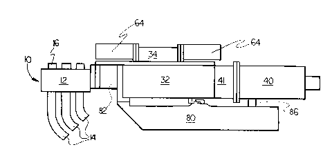
Figure l is a side elevational view of a gob
distributor made in accordance with the teachings of the
present invention;
Figure 2 is a view looking downwardly into the
lower casting of the ball screw housing; and
Figure 3 is an oblique view looking upwardly into
the upper casting of the ball screw housing.
The gob distributor includes a head 10 which has a
15 housing 12 supporting a number of gob scoops 14. These
scoops 14 receive and redirect gobs to a fixed array of
troughs (not shown) which feed discrete glassware
forming stations. The housing also supports a
corresponding number of gob receiving ends 16 which
20 receive gobs from a gob feeder and guide these gobs to
the scoops 14. As illustrated in figure 2, each gob
scoop 14 has a pinion 18 which interconnects with a rack
20 so that the gob scoops can be rotatively displaced in
unison through a desired angular range by selective
25 displacement of the rack.
The displacement of the rack is controlled by a
ball screw assembly 30 (figure 2) which is contained
within a housing having upper 32 and lower 34 parts
(figure l). As shown in figure 2, a ball screw 36 is
30 journalled into the right end wall 38 of the lower
housing 34. Rotation of the ball screw 36 by a servo

lZ796~S
motor 40 via a coupling 41, advances or retracts a ball
screw nut 42. To maintain this ball screw nut 42 at its
desired orientation throughout its displacement a
carriage 50 is secured to the ball screw nut 42 via
bolts 51. The carriage 50 extends towards one side of
the lower housing 34 and rotatably supports upper 52 and
lower (not shown) rollers which ride on flats 54 ~only
the top flat is shown) defined on a support rod 56
extending between the ends of the lower housing 34. The
10 carriage 50 also extends toward the other side of the
lower housing 34 and supports a pair of axially spaced
cylindrical bushings 58 which slide along a second rod
59. This rod 59 extends, parallel to the first rod 56,
between the ends of the lower housing 34.
The ball screw nut 42 is connected via a coupling
70 to the rack 20. The coupling includes a link 72
which is secured at its right, end to nut brackets 74
and which is secured at its other end to the rack 20.
As can be seen from figure 3, the carriage 50 also
20 includes an arm 60 which projects upwardly into the
upper housing 32 to intersect the axis of displacement
of the rods 62 of opposed single acting air cylinders
64. The rods 62 extend through the end walls of the
upper housing 32. The air cylinders 64 are normally not
25 in communication with Pressurized Air so that as the
carriage 50 is displaced between its advanced and
retracted positions the arm 60 will force each of these
rods 62 to a retracted position. When, however, the
power to the machine is shut off either by intent or
30 otherwise, or a power off signal is generated for any
other reason, a control solenoid S will operate to
connect the source of Pressurized Air to these air

1~'7966S
cylinders 64 thereby locating the arm between the fully
advanced rods 62 (a small clearance will remaln between
one of the rods 62 and the centered arm 60). The gob
scoops 14 will be in a neutral position, parallel to the
rack 20 and beneath the housing 12 of the head 10 when
this arm 60 is so centered.
The ball bearing housing is supported by a support
bracket 80 for pivotal movement about a vertical shaft
82 and the entire gob distributor including the head 10,
ball screw assembly 30 and the screw drive motor 40 and
coupling 41, can be pivoted from an operative position
to a remote position where the head will be removed from
beneath the gob feeder, by operating the retract
cylinder 84 which extends between a support bracket arm
15 86 and a lower housing arm 88.

Representative Drawing
A single figure which represents the drawing illustrating the invention.
Administrative Status

2024-08-01:As part of the Next Generation Patents (NGP) transition, the Canadian Patents Database (CPD) now contains a more detailed Event History, which replicates the Event Log of our new back-office solution.

Please note that "Inactive:" events refers to events no longer in use in our new back-office solution.

For a clearer understanding of the status of the application/patent presented on this page, the site Disclaimer , as well as the definitions for Patent , Event History , Maintenance Fee  and Payment History  should be consulted.

Event History

Description Date
Inactive: Expired (old Act Patent) latest possible expiry date 2008-01-29
Inactive: IPC from MCD 2006-03-11
Grant by Issuance 1991-01-29

Abandonment History

There is no abandonment history.

Owners on Record

Note: Records showing the ownership history in alphabetical order.

Current Owners on Record
EMHART GLASS S.A.
Past Owners on Record
ROBERT J. DUGA
Past Owners that do not appear in the "Owners on Record" listing will appear in other documentation within the application.
Documents

To view selected files, please enter reCAPTCHA code :


To view images, click a link in the Document Description column. To download the documents, select one or more checkboxes in the first column and then click the "Download Selected in PDF format (Zip Archive)" or the "Download Selected as Single PDF" button.

List of published and non-published patent-specific documents on the CPD .

If you have any difficulty accessing content, you can call the Client Service Centre at 1-866-997-1936 or send them an e-mail at CIPO Client Service Centre.


Document
Description 
Date
(yyyy-mm-dd) 
Number of pages   Size of Image (KB) 
Cover Page 1993-10-15 1 9
Abstract 1993-10-15 1 17
Claims 1993-10-15 2 32
Drawings 1993-10-15 3 61
Descriptions 1993-10-15 5 129
Representative drawing 2001-11-05 1 6
Fees 1995-12-14 1 27
Fees 1997-01-16 1 29
Fees 1994-12-12 1 33
Fees 1993-12-13 1 24
Fees 1992-12-22 1 20