Note: Descriptions are shown in the official language in which they were submitted.
1-~79668
The present invention relates to a magaæine for
stacking sheet-metal members, particularly for the production
of cans, having columns against which mutually remote edges
of the sheet-metal members are guided.
Such magazines are used, for example in accordance
with the Canadian Patent Application No. 504,127, filed on
March 14th, 1986, on welding machines for welding tongues
onto sheet-metal members which are subsequently processed
to form cylindrical can bodies. In magazines of this type
for these and other uses it is important that they should
be able to be loaded with stacks of sheet-metal members in
a simple manner and should keep these sheet-metal members
in a precisely defined position in such a manner that they
can be removed individually by means of a destacker working
automatically and be deposited in an equally precisely
predetermined position at one side of the magazine, for
example on a conveyor which conveys them for further proces-
sing. On the other haDd, a free spa~
1~79668
2.
provided between the columns of a magazine of this type,
which space is greater, by a tolerance range, than the
space requirements of the stack of sheet-metal members
which is to be introduced into the magazine. Certain
tolerances result already during the cutting or punching
to size of the individual sheet-metal members and in
addition, a lateral offsetting of the sheet-metal members
in relation to one another cannot always be completely
avoided during the stacking.
It is the object of the invention to develop
further a magazine of the type described at the beginning
in such a manner that, despite the said inaccuracies, it
is able to keep each individual sheet-metal member
stacked therein in as precisely a predetermined position
as possible ready for destacking.
According to the invention, the problem is solved
in that at least one column comprises a resiliently
yielding strip to exert a resilient pressure on the
associated edges of the sheet-metal members stacked
between this column and an opposite rigid column.
In the case of sheet-metal members which are not
too thin in relation to their surface measurements and
accordingly have an adequate stiffness, it may be
sufficient if the resiliently flexible strip exerts a
lateral force on the stack of sheets which is
- ~79668
substantially independent o~ its height. If the
individual sheet-metal members are comparatively thin,
however, and can accordingly be bent easily, which
applies to the majority of can sheets, a substantially
constant force exerted by the strip on the stack of
sheets might be too great when the greater part of the
stack has been used and the last sheet-metal member
remaining in the magazine is ultimately loaded with the
whole force of the pressure strip.
In order to avoid this, the invention is preferably
further developed in that the resiliently flexible strip
is divided into a plurality of pressure members which are
disposed one below the other and are individually
resiliently supported.
In this case, it is an advantage if the pressure
members are received in a common vertical groove in the
associated column.
In order that the sheet-metal members may not be
able to be caught in joints between the individual
pressure members, it is ~further an advantage if the
pressure members have surfaces deviating from a
horizontal plane at their adjoining ends.
One example of an embodiment of the invention is
described below, with further details, with reference to
diagrammatic drawings.
1'~79G68
Figure 1 shows the plan view of a magazine
according to the invention with associated devices for
conveying further,
Figure 2 shows the side view in the direction of
the arrow II in Figure 1,
Figure 3 shows the vertical cross-section III-III
in Figure 2,
Figure 4 shows a partial view in the direction of
the arrow IV in Figure 3 and
Figure 5 shows the partial section V-V in Figure 4.
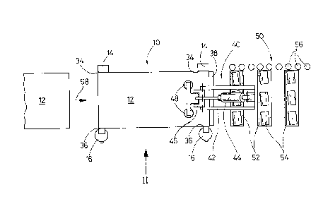
In Figures 1 to 3, a magazine 10 is illustrated
which contains a stack of rectangular sheet-metal members
12, for example of tin plate 0.2 mm thick. The magazine
10 includes two one-piece columns 14 of substantially
rectangular cross-section and two multi-part columns 16
of substantially circular cross-section. All the columns
14 and i6 extend vertically upwards from a common base
plate 18; the two multi-part columns 16 are adjustable
according to the width of the sheet-metal members 12.
Each of the two multi-part columns 16 comprises a
plurality of pressure members 20, ten in the example
illustrated, of substantially rectangular cross-section,
which are disposed one above the other, without any gaps,
in a vertical groove 22 and are displaceable horizontally
in this groove, towards and away from the one-piece
l~7s66a
column 14 situated opposite. Two radial bores 24
disposed vertically one above the other lead into the
vertical groove 22 behina each of the pressure members
20; guided in each of these bores is a screw 26 which is
screwed to the associatea pressure member 20 and limits
its movement towards the opposite column 14.
~ ach of the screws 26 is surrounded by a helical
compression spring 28 which is installed, with
preloading, between the associated pressure member 20 and
a shoulder 30 of the associated bore 24. Thus each pair
of associated compression springs 28 tends to urge the
associated pressure member 20 as far as possible out of
the vertical groove 22 in the multi-part column 16 in
question towards the opposite one-piece column 14.
The pressure members 20 are stepped at their ends
situated one above the other in such a manner that there
they each comprise a vertical face 32 which lies in the
common plane of the axes of the screws 26, as can be seen
from Figure 4. This stepped formation reliably prevents
the sheet-metal members 12 from penetrating into joints
between the pressure members 20 and becoming caught
there. The pressure members 20 are not, however,
prevented by this stepped formation from resilient
movements independent of one another in the axial
direction of the associated screws 26.
~796~8
~.
Ihe magazine 10 is open at its left-hand side in
~igures 1 and 2. In order to facilitate pushing in a
stack of sheet-metal members 12 from the left, the one-
piece columns 14 each have a chamfer 34; a chamfer 36 is
formed on each of the pressure members 20 in a
corresponding manner. At the right-hand side in ~igures
1 and 2, the magazine 10 is closed by a stop 38 in the
form of a vertical plate.
Associated wlth the magazine 10 is a destacker
40; this includes a frame 42 which is movable vertically
up and down and horizontally backwards and forwards in
the longitudinal direction of the sheet-metal members 12.
Pivotally mounted on the frame 42 at the top is the
~ cylinder of a pneumatic piston-cylinder unit 44 and
further down a link 46 in the vertical central
longitudinal plane of the magazine 10, parallel to the
plane of the drawing of Figure 2. Mounted on the link 46
is the piston rod of the piston-cylinder unit 44 to which
a pair of suction devices 48 is secured. In Figures 1
and 2, the destacker 40 is illustrated in a position in
which its two suction devices 48 are in the process of
grasping the uppermost sheet-metal member 12 in the
magazine 10.
The destacker 40 is followed by a roller conveyor
25 50; this includes lower rollers 52 and upper rollers 54
96~;~
7.
each of which can be driven in rotation about a
horizontal axis, the axes of the upper rollers 54
extending obliquely to those of the lower rollers 52.
The roller conveyor 50 i5 bounded towards one side by
lateral rollers 56, the axes of which lie in a vertical
plane parallel to the central longitudinal plane of the
.agazine 10.
In Figure 1/ an arrow 58 indicates that the
magazine 10 is loaded with a stack of sheet-metal members
12 in that this stack is pushed from the left in between
the pairs of columns 14 and 16 as far as the stop 38.
During the introduction of the stack, the pressure
members 20 on the two columns 16 are forced back somewhat
as a result of which the initial loading of the
compression springs 28 is correspondingly intensified.
Ihe sheet-metal members 12 are then urged towards the
opposite, rigid columns 14 by the pressure members 20
held in a precisely predetermined position as a result.
The screws 26 which limit the spring displacement of the
uppermost pressure member 20 on each of the two columns
16 are preferably adjusted so that these two pressure
~embers bear almost, or completely, without pressure
against the upper sheet-metal members 12 of those stacked
or even leave these a very small clearance and so do not
hamper the removal of the sheet-metal members.
~7~66~3
During the destacking, the sheet-metal members 12
are removed individually, during which the suction
devices 48 execute an arcuate movement upwards each time
the piston-cylinder unit 44 moves in and during this the
front edge of the sheet-metal member 12 in question is
moved somewhat away from the stop 38 and is finally
lifted away above this. The separation of the individual
sheet-metal members 12 is promoted by known means, for
example by like magnetization of superimposed edges of
the sheet-metal members 12 and/or by a stream of air
directed against these edges.
Each sheet-metal member 12, which has been lifted
away over the stop 38 by the destacker 40 is subsequently
lowered in such a manner that it comes between the
rollers 52 and 54 of the roller conveyor 50 and is
grasped and conveyed further by these. Thanks to their
precise positioning in the magazine 10, the sheet-metal
members 12 reach the roller conveyor 50 in a precisely
predetermined position in which they have only a very
short spacing from the lateral rollers 56. During the
further conveying, the inclined upper rollers 54 then
have the effect that the sheet-metal members 12 bear
against the lateral rollers 56 after a very short
conveying distance and, as a result, are positioned for
further processing, for example for the provision of
~796~8
~.
longitudinal scorings which define a tear-off strip.