Note: Descriptions are shown in the official language in which they were submitted.
8009~
The present invention relates to the field of luggage and
carriers.
Provided by the present invention is a deviee with which
the effective carrying capacity of a piece of hand luggage, such
as a briefcase, can be substantially increased, without any
structural modification of the luggage. More broadly speaking,
however, the object of the present invention is to provide a
device which may be used -to supplement the carrying capacity of an
existing piece of luggage, or to enable an existing piece of
luggage to be used to carry ob~ects which otherwise it could not
carry.
In one broad aspect, the present invention relates to a
carrier for attachment to a piece of luggage which has a handle,
such as a briefcase or a suitcase, said carrier ineluding: (i) a
-top panel with an aperture through which a said handle can
project; (ii) a back panel, extendin~ from said top panel, and
when in use, at a substantially right angle there-to; (iii) means
associated with sai.d baek pane:l for carrying objects.
In drawings which illustrat~ the present invention by way
of example:
Fig. 1 is a perspective view oE a Eirst embodiment of the
present invention, mounted on a briefcase which is shown in
phantom;
Fig. 2 is a perspective view of a second embodiment of
the present invention, also mounted on a briefcase which is shown
in phantom,
Fig. 3 is a perspective view of a third embodiment of the
--1--
~oo~
present invention also mounted on a briefcase which is shown in
phantom,
Fig. 4 is a perspective view of a modified form of the
embodiment shown in Fig. 1.
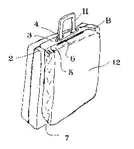
Referring to the drawings in general, and especially to
Fig. 1, the present invention provides a carrier 1 which is used
to augment the capacity of a briefcase B (or other piece of
luggage) which is provided with a handle H. The carrier 1 of the
present invention includes a main back panel 2 which, in use, lies
substantially flat against the side of briefcase s. A top panel 3
is integral with the back panel 2, and is provided with a
substantially rectangular aperture 4 of a size selected to fit
over a standard briefcase handle H. In practice, it has been
found that an aperture size of 15 cm long X 2 cm wide will
accommodate most briefcase handles ~1.
Using top panel 3 with aperture 4 and back panel 2 as a
base, various modifications each re~ultin~ in a different carrier,
and a different embodiment of the pres~nt invention, are possible.
For instance, in Fi~. 1, side panels 7 are provided, and a front
panel 12 continuous along a common hottom area with back panel 2
is provided, so that a rectangular sack carrier is obtained. The
top edge of the front panel 12 defines a closure panel 15 to close
the top of the carrier. The underside of the closure panel 5 is
preferably provided with a velcro strip 6 - either a hook or a
pile surface - and a complementary surface is provided on the top
panel opposite. It should be noted that closure panel 5 can as
easily extend from top panel 3 outwardly, to a closure strip on
* cJe~ r> ~ ~Jc 5 ~r~ ~r~ ' 1 --2--
l;~ao~9~
front panel 12, as in Figure 4.
In the embodimen-t illustrated in Fig. 3, a number of
pairs of elas-ticized straps 8 are provided on the back panel, the
carrier of the present invention thereby being susceptible of use
as a roll carrier for carrying charts, maps, plans, drawings,
umbrellas and the like. Each strap has one end attached to the
back panel, and one free end, which can be looped around a roll.
Opposite ends of each strap are provided with complementary hook
or pile velcro surfaces 9, so that the strap may be securely
wrapped around a roll, yet easily released. Moreover, it will be
understood that similar pairs of straps 8 may be provided on front
panel 12 of the carrier of Figure 1, to obtain a combination type
carrier, useful for carrying, for instance, a quan-tity of notes
and some engineering drawings.
The embodiment of the present invention illustrated in
Figure 2 is a coat carrier. It will be seen that with the
addition of a Eront panel 12 extending upwardly from the lowermost
portion oE the back panel, a slirlg-type arrangement can be
achieved. ~ velcro stri~> ~ is u~ed to keep this carrier closed.
In Figure 4, a variation of the carrier pack shown in
Fig. 1 is illustrated. That is, by constructing the pack with
wider side panels, and providing a zippered racket-pocket 10, a
sports bag type of carrier is obtained.
A further modification which may be applied to any of the
embodiments illustrated is shown in Fig. 3. That is, a pair (or
any desired number) of retaining straps 11 may be provided,
extending from adjacent the side edges of the back panel, around
lX800~4
the briefcase, and into engagement with corresponding retaining
members - such as short straps provided with D-rings - which
extend from the rear mos-t edge of the top panel. If a D-ring
arrangement is used, it is preferred that the outermost surface of
the free end of the strap is provided with two complementary
velcro surfaces. A hook surface is located near its end, and
inwardly from there, a pile surface, so that the end of the strap
may be passed through the D-ring, and then strap may be tensioned
and fastened by pressing the hook surface into the pile surface.
In a preferred embodiment, the carrier of the present
invention is made from a waterproof nylon material, such as Dupont
CORDURATn, which may be treated with ~urther surface finishes, such
as GORTEX'n.
It will be understood that the present invention is not
limited to the embodiments described above. Various modifications
of the present invention, resulting in may diEferent forms of
carrier will be apparent a.~ter consultation of this disclosure.