Note: Descriptions are shown in the official language in which they were submitted.
1~80~38
--1--
PERIMETER SEAL AND SEALING SYSTEM
This invention relates to a perimeter seal and
sealing system, which is particuarly suitable for use in
motor vehicles, and to a method of forming a seal between
two members, such as between a vehicle door and the door
opening.
One type of door seal for motor vehicles has a
fixing portion, from which a sealing portion extends,
which fixing portion is located in a 'C' (shaped) channel
on the perimeter of the door, or possibly the perimeter of
the door opening. Other methods for fixing such seals in
position include using adhesive or two-sided tape, or
plastics pegs engaging in apertures in the base of the
channel, a flange on the door or perimeter of the door
opening; however, such methods suffer from the following
disadvantages:-
a) On assembly the operator tends to damage the
painted surface of the 'C' channel, therefore starting a
rusting cycle.
b) The base of the 'C' channel cannot be
successfully sealed against water ingress therefore
allowing a potential leak situation to exist at all times.
c) When using plastic pegs, the operation of
punching holes is difficult. Furthermore, the frequency
of pegs required to give a reasonable retention is
~5 impractical. Peg mounted seals also tend to ~cross
corners~, therefore reducing the satisfactory functioning
of the seal.
d) Two-sided tape and adhesive give problems on
assembly and the serviceability gives grave problems.
e) Rolled sections of metalwork are expensive to
form and not very rigid and it is preferred to retain the
~meatplate~ approach of door construction to ensure the
best build tolerance situation, i.e.to manufacture the
~.
3~3
door from two spaced dish-shaped components which are
welded together around their edge flanges.
The present invention therefore seeks to provide a
seal and sealing system which overcomes the above
disadvantages, and which gives the opportunity for the
seal to be as far outboard of the aperture as possible
and thereby offer optimum sealing and noise reduction
efficiency. Further, the invention also seeks to
provide a seal which is easy to install onto the vehicle
io and has good retention after fitting, and ensures
minimum damage, in the fitting process, to metalwork and
which also makes the best use of the latest
manufacturing equipment, i.e. robots, for the assembly
of the metalwork areas on the vehicle.
An aspect of the present invention is as follows:
A seal suitable for use as a door seal in a motor
vehicle, said seal having a fixing portion and a sealing
portion and wherein the fixing portion comprises a
resiliently deformable carrier located at least partly
in a polymeric material, said carrier having a plurality
of resiliently deformable limbs extending transversely
of the fixing portion throughout its length, and wherein
a channel is formed in said polymeric material,
extending lengthwise of the seal, and on either side of
said carrier, thereby exposing the carrier in the
location of the channel, and wherein the spacing between
adjacent limbs of said carrier is such that an enlarged
head of a stud may be forced between adjacent limbs
during fitting of the seal ~o that the seal can be
fitted to a part to which the stud is connected, and
secured to the part by engagement between the underside
of the head and said adjacent deformable limbs.
Preferably, the seal is extruded from one or more
polymeric materials, and the carrier is embedded in the
fixing portion, which may be formed of a different
~ . ~.....
38
material from that of the sealing portion. Preferably
also, the carrier extends across substantially the whole
width of the fixing portion, with a region of the
carrier not being embedded in the polymeric material of
the fixing portion so that the studs can be forced
easily between adjacent limbs of the carrier.
It is important that the durometer of the polymeric
material of the fixing portion is sufficiently high to
hold the fixing portion firmly against the vehicle body
(or door) throughout the length of the seal. However,
it should be low enough to allow the seal to be bent
around corners, e.g. of a door opening.
Preferably, the carrier is formed of wire formed
into a zig-zag configuration with generally parallel
limbs, any adjacent pair of which is joined together by
a U-shaped edge portion of the carrier, and which limbs
provide wefts which are held in their generally parallel
configuration in known manner by parallel spaced warps
knitted into the wefts. The carrier may be of the type
disclosed in European Patent Application No. 83303150.3
or 84306335.5.
Preferably, the wire is formed of a highly
corrosion-resistant material such as stainless steel.
Other aspects of this invention are as follows:
A sealing system comprising a sealing member for
forming a seal between two relatively movable parts, and
a plurality of studs having enlarged heads, the studs
being secured to one of the parts between which the seal
is required, with their heads pro~ecting from said one
part, prior to engagement of said sealing member with
said one part, and a sealing member comprising the
fixing portion, a sealing portion and a resiliently
deformable carrier located at least partly in said
fixing portion, said carrier having a plurality of
resiliently deformable limbs extending transversely of
the sealing member throughout its length, said sealing
~ ..
i~()l3~
3a
member being engaged with said studs with said studs
being entrapped between adjacent limbs of said carrier.
A method of attaching a seal to a member, said seal
incorporating a carrier therein, which has a plurality
of exposed resiliently deformable limbs extending
transversely of said seal throughout its length,
comprising the steps of attaching a plurality of studs
with enlarged heads to said member, and then attaching
said seal to said studs by passing said heads of said
studs between respective adjacent pairs of limbs of said
carrier, the spacing between adjacent ones of said limbs
being such that the heads of said studs may be forced
between adjacent ones of said limbs during fitting of
said sealing members to said one part, said seal being
secured to said member by the underside of said heads
engaging said limbs.
The invention is now described by way of example
with reference to the accompanying drawings, in which:
FIGURE 1 is a typical transverse section through a
seal; and
FIGURE 2 is a section on the line II-II of Figure 1
1~8()138
--4--
with some of the material of the seal omitted for the sake
of clarity, and showing the position which a head of a
stud would occupy when the seal is fixed in position as
shown by the chain line outline in Figure 1.
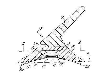
Referring to the drawings, 1 represents the surface
of a flange, e.g. around a door opening in a motor
vehicle, to which a plurality of enlarged headed studs 3
have been welded, by means of which a seal 4 may be
attached to the vehicle around the door opening. A
particularly suitable make of stud is that produced by
Tuc~er Fasteners. The stud is T-shaped and is made from
stainless steel thus reducing the possibility of corrosion
if slightly damaged on assembly. The stud is welded onto
the metalwork of the vehicle with the use of an automatic
welding system carried by a robot. This means that the
stud can be orientated in any required position, the only
restriction being the size of the welding head which at
the present time is 18mm in diameter. The dimension
between the base of the stud head and the surface of the
vehicle metalwor~ can vary,a typical dimension being from
2.5mm to 2.3mm. The diameter of the head and the shank of
the stud are important, as will be described, but
typically the head diameter could be 5.05mm ~/- O.5Nm and
the shank diameter 3.Omm +/- 0.5mm. The overall design of
the head of the stud may include a tapered condition to
ease assembly.
The seal 4 is extruded from one or more polymeric
materials and has a fixing portion 5, a sealing portion 7
and partially embedded in the fixing portion 5 is a
knitted wire carrier 9.
The wire carrier 9 acts as a reinforcement for the
fixing portion 5 or base of the seal 4 to malntain the
integrity of the seal when negotiating complex or sharp
radii, e.g. around door openings, and is also the prime
means for fixing the seal 4 to the flange 1 of the
vehicle. The wire carrier 9 is shown in Figure 2, and
comprises wire bent into a zig-zag formation 80 as to have
a plurality of generally parallel limbs or wefts 11,
connected together at their ends by U-shaped edge
~80138
--5--
portions 12. Obviously, the opposite ends of each limb to
those illustrated in Figure 2 will be connected not to the
ones illustrated but to its adjacent limb on the opposite
side of the one shown as being joined by a U-shaped edge
portion 12 (see top right hand corner of Figure 2). The
wefts 11 are maintained in their illustrated position by
means of a plurality of generally parallel warps 13, only
one of which is shown in full, connected by a known
knitting or knotting process to each limbs 11. Other
warps are represented by the broken lines 15.
As can be seen from the drawings, the polymeric
material of the fixing portion is extruded only over the
edge regions of the carrier 9, leaving a rectangular
sectioned central channel 17 across which the carrier 9
lS extends. This channel is somewhat wider than the heads of
the T studs 3, so that the shanks 19 of the studs can be
located between adjacent limbæ of the wire, with the heads
21 holding the seal on the studs 3. The wire carrier can
include ~phantom warps~ 23 to allow the centre section of
the wire to be warp-free when the section is extruded and
thus allow the studs to be inserted freely between the
limbs 11. This can be achieved by forming these of a
material which melts during extrusion of the seal (such as
polypropylene). It will be appreciated that the frequency
of limbs 11, i.e. their spacing, is determined by the size
of the T stud to be used and for studs of the
above-mentioned diameter, there are about six limbs 11 per
inch.
The material of the wire should be corrosion
resistant to ensure that no corrosion takes place in
service because the wire will be the only fixing medium so
a failure would be unacceptable. The wire must be
malleable enough to be formed easily but on application
have sufficient resistance to bending to produce the
required retention characteristics.
A typical diameter for the wire is 0.76mm but this
1~30`138
--6--
may be varied, and the width of the wire carrier is about
22mm, but obviously the width can be varied according to
the actual requirement.
In the illustrated seal, the wire carrier is
encapsulated by an elastomeric polymer compound (possibly
based on EPDM rubber) which forms the base or fixing
portion 5 of the seal. This provides a good seal against
the face of the flange. The seal is improved by having
sharp edges 25 on each edge of the fixing portion 5. The
grade of polymeric compound must exhibit sufficient
flexibility to negotiate corners. Ideally, the compound
should have a durometer which iæ sufficiently high to hold
the seal throughout its length against the vehicle body
(with the aid of the carrier 9). In many instances the
seal will have to be bent around corners of door openings,
and for such seals, the durometer of the compound should
be low enough to permit such bending without detracting
from the other requirements of the seal.
The sealing portion 7 is illustrated in the form of
a polymeric sponge flip, but it will be appreciated that
many other different constructions could form the sealing
portion to seal between the two moving parts of the
structure of the vehicle, i.e. door and body. This part
of the seal needs to be flexible enough to conform to the
variations experienced in practice, e.g~ (a) a nominal
door gap of 16mm, (b) an unpainted body build tolerance of
+/- 2mm, (c) a high speed ~suck out~ condition of +3mm,
i.e. the seal must be sufficient to maintain a seal
between vehicle door edge and door opening even at high
speeds when there can be a tendency for the door to move
outwards around its periphery by up to 3mm.
The sealing portion 7 is co-extruded with the fixing
portion 5 and the wire carrier 9 and has to be of
sufficient softness to conform easily to the body
variations and give acceptable door shut efforts but have
sufficient modulus to provide a seal.
Obviously, the above described seal is just one
1~0138
--7--
possible example incorporating the invention. The shape
and size of the sealing and fixing portions 7 and 5 could
be quite different, as could their relative positions.
Likewise, the studs could be of a different shape.
Furthermore, it is envisaged that non-extruded seals could
be used, e.g. the carrier 9 could be covered with textile
or other material, or uncovered, and hidden, for example
by a textile or pile sealing portion. Furthermore, it is
not essential that the studs 3 should engage a central
region of the carrier 9.
It is also envisaged that the carier 9 could be of a
different construction to that illustrated. While it is
preferably formed of knitted wire, it might be possible to
use some constructions of slotted metal carrier, for
example.
The seal of the present invention allows vehicle
manufacturers to fix the T studs 3 to the vehicle with
robots to allow flexibility of design, ease of manufacture
and consistency of process. Furthermore, the invention
allows the use of current wire carrier technology in a
novel form to allow ease of seal fitment with good
retention characteristics for the seal, i.e. the wire
carrier has the new task of holding the seal on the studs.
Another advantage is the elimination of the
recurring corrosion problems experienced by traditional
methods of seal fixing systems, and yet a highly flexible
seal is provided, which is easy to fix in position.
It will of course be understood that the present
invention has been described above purely by way of
example, and modifications of detail can be made within
the scope of the invention.