Language selection

Search

Patent 1280337 Summary

Third-party information liability

Some of the information on this Web page has been provided by external sources. The Government of Canada is not responsible for the accuracy, reliability or currency of the information supplied by external sources. Users wishing to rely upon this information should consult directly with the source of the information. Content provided by external sources is not subject to official languages, privacy and accessibility requirements.

Claims and Abstract availability

Any discrepancies in the text and image of the Claims and Abstract are due to differing posting times. Text of the Claims and Abstract are posted:

  • At the time the application is open to public inspection;
  • At the time of issue of the patent (grant).
(12) Patent: (11) CA 1280337
(21) Application Number: 1280337
(54) English Title: METHOD AND APPARATUS FOR DIVIDING AND UNITING THE FLOWS OF HIGH-CONSISTENCY FIBRE SUSPENSIONS
(54) French Title: METHODE ET DISPOSITIF POUR DIVISER ET CONJUGUER DES DEBITS DE MELANGES FIBREUXEXTRA-DENSES
Status: Expired and beyond the Period of Reversal
Bibliographic Data
(51) International Patent Classification (IPC):
  • D21F 1/02 (2006.01)
  • D21F 1/06 (2006.01)
(72) Inventors :
  • NISKANEN, TOIVO (Finland)
  • REPONEN, VOITTO (Finland)
(73) Owners :
  • AHLSTROM MACHINERY OY
(71) Applicants :
  • AHLSTROM MACHINERY OY (Finland)
(74) Agent: GOWLING WLG (CANADA) LLPGOWLING WLG (CANADA) LLP
(74) Associate agent:
(45) Issued: 1991-02-19
(22) Filed Date: 1986-01-24
Availability of licence: N/A
Dedicated to the Public: N/A
(25) Language of filing: English

Patent Cooperation Treaty (PCT): No

(30) Application Priority Data:
Application No. Country/Territory Date
850307 (Finland) 1985-01-24

Abstracts

English Abstract


Abstract
A method and an apparatus for dividing and uniting flows
of high-consistency fibre suspensions. To prevent
clogging of the distributor the fibre suspension is
caused to flow into a space uniting the inlet and the
outlet flows, where a turbulent flow extending to the
valves regulating the discharge flow created. The
distributor comprises a vortex chamber provided with an
inlet and outlets and with regulating valves connected to
the outlets and disposed at a short distance from the
outlets. According to a preferred embodiment of the the
invention, a rotor provided with vanes is disposed in the
vortex chamber,


Claims

Note: Claims are shown in the official language in which they were submitted.

The embodiments of the invention in which an exclusive
right or privilege is claimed are defined as follows:
1. A method of dividing and/or uniting flows of high-
consistency fibre suspensions in a pipeline said suspensions
having a consistency of between 8% - 15% comprising supplying
the fibre suspension to a vortex chamber having either one
inlet and a plurality of outlets for dividing or a plurality
of inlets and one outlet for uniting inlet and outlet flows
through the vortex chamber, subjecting the high-consistency
suspension to an intensive shear force field sufficient for
breaking the bonds between the fibres of the fibre network
and thus making the high-consistency fibre suspension
flowable.
2. A method a recited in claim 1, wherein the fibre
suspension is caused to flow into the space uniting the inlet
and the outlet flows, in which space a turbulent flow
extending to the valves regulating the discharge flow is
created for preventing the fibres from forming a solid
blockage in front of a valve.
3. A method as recited in claim 2, wherein some of
the valves regulating the flow are closed.
4. A method as recited in claim 1, wherein the
turbulent flow is created by a rotor.
5. An apparatus for location in a pipeline and for
dividing and uniting flows of high-consistency fibre
suspensions, having the consistency of between about 8%-
15%, comprising a vortex chamber having either one inlet and
a plurality of outlets or a plurality of inlets and one
outlet connected to said vortex chamber and means in said
vortex chamber for subjecting the high-consistency suspension
to an intensive shear force field for breaking the bonds
between the fibres of the fibre network and thus making the
high-consistency fibre suspension flowable.

6. An apparatus as recited in claim 5, comprising
regulating valves connected to the outlets and disposed at a
short distance from the outlet openings.
7. An apparatus as recited in claim 5, wherein the
vortex chamber is provided with a rotor for creating a strong
shear force field.
8. An apparatus as recited in claim 7, wherein the
rotor is provided with vanes.
9. An apparatus as recited in claim 5, wherein said
valves are positioned to be less than one half of a diameter
of said outlet openings away from the inner surface of the
vortex chamber.
10. An apparatus as recited in claim 5, wherein one
or more regulating valves are connected to the outlets and
disposed at a short distance from the outlet openings or
positioned to be less than one half a diameter of said outlet
openings away from the inner surface of the vortex chamber in
order that the turbulence field created in the flow extends
to the valves.
11. An apparatus for dividing and uniting flows of
high-consistency fibre suspensions, having the consistency of
between about 5% - 20%, comprising:
a vortex chamber for distributing said fibre
suspension, said vortex chamber including at least one inlet
opening and a plurality of outlet openings, said inlet and
outlet openings all being spaced from each other;
an inlet channel connected to said at least one inlet
opening and extending outwardly from said vortex chamber;
a plurality of outlet channels each connected to one
of said outlet openings and extending outwardly from said
vortex chamber;
inner surfaces of said vortex chamber around each of
said outlet openings forming a sharp angle with each of said

outlet channels, edges between said surfaces and said outlet
channels being non-rounded so that a major part of the
kinetic energy of the suspension flowing through said vortex
chamber is converted into turbulent energy; and
a regulating valve connected to each of said outlet
channels at a short distance from each respective outlet
opening, selected ones of said regulating valves being closed
for regulating the flow of the suspension through said vortex
chamber, a rotor mounted for rotation about an axis in said
vortex chamber for increasing the turbulence of the
suspension in said vortex chamber, said rotor includes a
plurality of vanes extending radially of said axis, said axis
extending substantially transversely to each of said outlet
channels, said axis of said rotor extends axially of said
vortex chamber, each of said valves are positioned less than
one-half the diameter of a respective outlet opening, away
from an inner surface of said vortex chamber.
12. An apparatus according to claim 11, wherein each
vane of said rotor has a radius from an outer tip of said
vane to the axis of said rotor, said rotor having an axial
length equal to about six times the radius.
13. An apparatus for dividing and uniting flows of
high-consistency fibre suspensions, having the consistency of
between about 5% - 20%, comprising:
a vortex chamber for distributing said fibre
suspension, said vortex chamber including at least one inlet
opening and a plurality of outlet openings, said inlet and
outlet openings all being spaced from each other;
an inlet channel connected to said at least one inlet
opening and extending outwardly from said vortex chamber;
a plurality of outlet channels each connected to one
of said outlet openings and extending outwardly from said
vortex chamber;
inner surfaces of said vortex chamber around each of
said outlet openings forming a sharp angle with each of said
outlet channels, edges between said surfaces and said outlet

channels being non-rounded so that a major part of the
kinetic energy of the suspension flowing through said vortex
chamber is converted into turbulent energy; and
a regulating valve connected to each of said outlet
channels at a short distance from each respective outlet
opening, selected ones of said regulating valves being closed
for regulating the flow of the suspension through said vortex
chamber, each said valve is positioned at a location which is
less than one-half the diameter of an outlet opening away
from an inner surface of said vortex chamber.
14. A method for dividing and uniting flows of high
consistency fibre suspensions, comprising:
supplying the fibre suspension, having a consistency
of between 5% - 20% to a vortex chamber having a distributor
space therein with at least one inlet opening and a plurality
of outlet openings for uniting inlet and outlet flows through
the distributor space, said inlet and outlet openings being
spaced from each other;
providing a plurality of outlet channels each
connected to one of said outlet openings and extending
outwardly from said distributor space;
providing said distributor space with an inner surface
around each outlet opening which forms an edge in said
surface between said outlet opening and said outlet channel
connected to that outlet opening which is sharp and
substantially non-rounded;
creating turbulent flow by means of angularly
disposed interior surfaces in the distributor space so that
the fibre suspension is subjected to shear forces for
dividing the fibre suspension for flow out of said outlet
openings, and
positioning each valve at a distance of less than one-
half the diameter of an outlet opening away from said
distributor space.

Description

Note: Descriptions are shown in the official language in which they were submitted.


~ ~ul
~8~3~
M:E:THO~ AN~ APPAR~TUS ~OR ~IVIDING AN~ UNITING THE ~LOWS
t:~ HIGH-Ct~NSIS~EN~Y FI~R~ SU~PEN8IONS
~rhe pr~enc lnven1:ion relA~e~ to a method ~nd ~
appa~atus for di~rid~slg ar~d uni~lng ~he flows Oæ h~gh-
con~igtençy fi~r~ ~u~pension~. I
Th~ pulp indu~ry o:~ten requires that f~bre ~uape~lon i~oon~re~ed ~rom a vsssel o~ a pipe aon~inuou~ly or inter-
n~ltten~ly div1 ded evenly or in a de~aire~ ma~n~r ~
several di~erent place t e,g. ~rom A 3tora~e ~ank ~o ~wo
or more pro~e~sing devices. When the consist~ncy o~ the
su~pen~ ion ~ ~ low, i . e . up ~o approx . 5 per cent, no
pxoJ~lem6 ari~e, bu~ whan the ~o~ tency i~ higher ther~
i~ lit~le free liquid between the ~ibre~ ~n~ e flbres
~or~ re network the ~ituat~on i~ ~uit~ differ~n~.
Wh2n ~h~ consi~teno~ 1 s high, ~g. ~rom ~ to 15 per c~n~,
~he fibre ~u~pen$10n ~rm~ ~ stron~ fibre network an~
dividing and ~lniting fibre sugpenslon~ in a pipe Line i~
often impossible without spocial mea~re~. When ~
h' ~h-~on i~tency fibr~ s~l~pension arri~r~s a~ a junction
poin~ in the plpe lln~, ~he Pibre ne~worlc may ~Q l~C~O
~trong ~o be disper~ed. I~ iB po~sibJ ~ th~t th~ fi~rQ
network ~ick~ to a par~ of the pipe whl~h re~ul~ in
p~c~pitation a~ clogging of the p:lpe llne~ When one
branch o~ ~h~ pip~ 1~ n~ is not irl u~e and i~ closed l~y a
v~lv~, the p~tlor, of the pipe pr~3cedlng ~he valve i~
~asily clogge~ ~ncl cloes not s;~pen when the ~alve i~
opena~ .
I
B~cau~ of the ~t~n~ ~ib~e ne~o~k~, high~con~ist~ncy
pulp ~lows from l~r~n~h pipe~ ~an not be ~ombine~ in a
pipe lina. Wlthout spe~ial mea~ure~ th~ e n~twork~
pr~ven~ t~70 ~lows of A ~maller dl~me~er from ~orm ng a
.,. I

FRt
33~7
flow with a lar~er diameter.
Th~ ~bo~e proble~3 in dividing ~nd unlting the 9~1uw~ ~xe
~olded by ~ubject~n~ kh~ :Clow ~o ~uch an ~'cen~i~e
o~ ~hear force~ tha~ he l~onds betwe~n th~ res ~r~
brok~n ~nd a turbulent flow i~ crea~ed w~exe no fibre
networXs pr~entlng the division an~ ~ombina~lon of ~h~
6uspen~ion~ e:~ig~ ~he ~hear forae~ ~an be c~a~ed by
the geometry o~ the ~una~ion point or by a ro~or.
~he o~je~t of the pr~ent lnventlon i~ ~o provide a
me~hod and an appar~tu~ by wh~ ~h ~he Plow o~ a fil~re
~usp~n~i.on of the oon~ enay of 5 to 2~ per ¢en~ can be
dlvide~ a~d united in a ~on~roll~d manner"
~h~ e o turbulence to disrupt fi~re bon~
pret~iously ~i~clo~ed e~g. ln ~inni~l~ pAtent no. 51116 ~nd
~inni~h pat~nl; ~liaatlon no. 7810710
The ~orrn~r o~ the~e publioatlon~ di~lo~ a pulp
di3'crib~ltor ~onnec~ed ~o a ~he~ ~or~a~ion device in
whiah the ~ow i~ aoc~slerat~ in a taperin~ por~ion o~ a
pipe and ig c~uæed ~o implnge at high speea ~gain6 a wall
whl~h forces th~ ~1QW radially outward~ to the ou~let~
~ pos~d around t~e impln~emen~- a~ea.
The latter o~ ~hR publicatiQns di~lClCIBe!E~ a ~e~ice or
~emo~ing pulp from a v~s~el ln whiah a pump connecte~l ~o-
the c~utlet of the pulp ves~el i~ provlded with a ro~or
~xtending into the v~sel.
Th~ main ahar~eri~:i a fea~cuxe of ~ho pra~ent lnvention
i~ that the ~ibre ~u~pension is c~u~ed to flow int~ ~
space unl~ing the ~nle1: and tl~e ou~let ~low~ in ~hich
~pace a ~ortex flow i~ created to prev~nt a ~ill pocket-
!
!

337
like state o~ the ~ pension .
~he vc~r~x flow i~ pre~erably &reate~l by a ~tor,
The ~pparR~U~ fox carr~ing ou~ ~he invent~on 1charac~erl~ed by a ~rortex ohamber pro~idod with irl~ts
and outlets.
The ln~en~ion i9 d~seri~ed in detail b~lo~ wi~h re~exen~e
to ~e ac~ompanying dxawing6 whi~h 1 11UB~rAte preferred
~mbo~iment~ of ~he appar~tuses ~Qr ~rryin~ ou~ the
method o~ ~he inv~ntion.
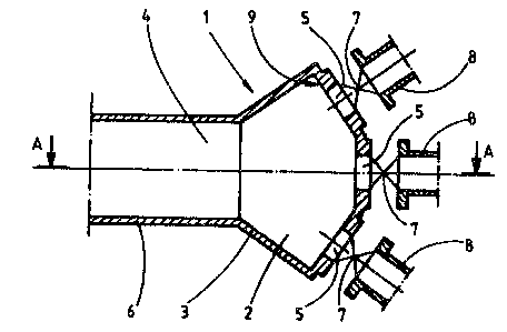
Fig. 1 i~ a longitudinal aros~ section along ~ e E~-B C~
~he distr1butor o~ fig. ~.
Fig. 2 i~ a ~ec~`on along lin~ of fig. 1.
~ig. 3 1~ a se~tion along line D-E~ o~ fig. 4 ill~l tratin~
an o~her embodiment of a di~tribu~or~
Fi~ . 4 i6 a se~tion ~ l~ng line C~C r~f Fig . 3 ~
~ig~ 5 i~ a ~ection alon~ e ~-F o~ ~ig. ~ illust:r~ting
a thi.~d al~ernatitre ~mbodiment of 2 di~ributor~
~ig. 6 i~ a 6e~tion along line E-E o~ . 5.
~ig. 7 i~ a ~ec~ion along line f~-H of ~ , 8 ~llu~tra~:ing
~ ~ourth embodiment of a di~ril~utor.
Fig, 8 i~ ~ s~otion along line G-G o~ ~lg~
In the di~tribu~r 1 illu~tra~ced ln ~ureQ 1 ~nd ~, the
numaral 2 re~r~; 'co a ~Jortlax ch~mber ~ w~ o~ whi~h

FR
~ao~37
proviasd with an inle~ 4 an~ outlets 5. An inlet plp~
6 i Q connec~d to the inle~, th~ ou~ re p~ovi~
with r~gulatinq ~7alve~ 7 tc whi~h ou~let plpe~ B B~t
~onne~ted. The re~ul~ing valve~ ~re di~po~d at d shOrt
d~ nce from the lnner sur~e ~ of the vort~ax chamher
(Cd/~, where d i s th~ diarneter o~ ~he ou~let 5~
~uspension is supplied ~ he inle~ pipe 6 at a hi~h
velocity (~3~n/s) to ~he vort~x ~hamber ~ in which
tur~ul~n~ p~evenl:ing the formation o~ ~ibre networks i~
~ated l~y the ch~nge6 of ~ r~ct.ion ~au~ by the ~mall
~rol~ms, the expan~ion o~ ~low and the angul~ ~hape of
the chamber even i~ some of ~he valves were ~lo~ed. A
nlajor part of the kinetic ener~y ~ th~ flbre ~u~pen~ion
is ~ran~or~ned i~to turbulent ~ner~y. . ~he higher th~a
veloci~y o~ ~he isllet flo~ and ~he ~mallex ~he V~rt~3x
ch~mher i~, the gr~ater i~ the intensity of the
turhul~nce and it~ di~uptinçt effect on the ~ibr~3 bond~,
The fibre ~uspension i9 removad ~om the vor~ex chamber
through t:he regulatin~ valve~ and a~ suppliad ~hrough the
branch pi.pes 8 to pro~s~ device~ which are not
ilîustrated. Tne valves c~n be u~ed ~o~ ul~ing th~
fibre ~uspensions ~low~ to the process devi~es
required. The diame~er o~ ~he bran~h pipe~ can ~e equ~l~
as illu~ate~ in the drawin~s, or une~ , The ~o~tex
~lo~ exten~lln~ to the inle~ of ~h~ valvas p~even~ plu~R
from b~ g formed in f~ont of ~he valv~3 ~h~n ~hey a~
~lo~ed .
The di~rubu~or 11 illu~traéed in figures ~ and 4 i~
equsl to 'che em~odiment o~ ~igu~e~ 1 and 2 with ~he
excep~ n of 1~ vortex chambe~ 12 ~h~ ~hape o~ wliiçh i~
~ifferen~ .
The di~ibutor 1 illu~tra'ced in ~i~ures S A~

FF~
;~ 8 0 3 37
compri~es a ~ylindri~al vortex chamber ~ provid~ wl~h
an inlet 24 to whi~h an lnl~t pipa 26 i~ corlnec~. A
vortex chamber w~Ll 23 shows fotlr otltlet~ 25 dl~po~d at
an eqllal ai~tance rom each o'ch~r, to whi~h the ou~
pipes 28 ~e connec~ed through r~ulatlng ~al~e~ ~7~ A
rotor 30 pxovi~e~ wl~}~ v~ne~ d~ ~posed in the vurtex
ch~nlber. ~he sha~t ~g o the roto~ 18 mounte~ on
be~rings ~nd the rotor ro l:ated by known ~ethod~ .
rhe aesired turbulont flow 18 cr~Ated by rotating the
rotor. `rhe r~nge of the rotor is ~pp~ox,. 6 R ~7he~e R i~
the distance o the vane outex edge ~om th~ sh~t ~en~er
line.
ln the d~ ~ributor 41 illu~trate~ in ~i~ures 7 ~nd g the
~o~itiorl of tha inlet pipe 46 and the outlet plpe 48 in
rel~lon ~o the ro1:or 50, ~nd the shape of ~he voxtex
ch~7nher 42 and the ro~or are di~ar~n~ ~rom those of the
embodimen~ illu~trated in f~g~lre 5 an~ Ç, b~
oper~tl~n prin~iple 18 the 6ame.
The lnvention is al60 appll~a~le for feeding se~eral
f ibr~ suspen~ion ~low~ in~o ~ vort~x eha~ber asl~i
di~charging ~hem as ona g~low.
~he invention ls not li~nited by the embo~imerl~s
~ llu~ra~ here a~ e~amples only, but lt c~an b~ applied
and modl4ied wi~hln the ~cope of protec~ion defir~ed by
thQ patent clalm~. E.g. an appara~cu~ accoraing ~o ~h~
inven~io~ may compri~e a p~urallty o~ inl~ pipes ~nd c
plurality o outlet pipes,

Representative Drawing
A single figure which represents the drawing illustrating the invention.
Administrative Status

2024-08-01:As part of the Next Generation Patents (NGP) transition, the Canadian Patents Database (CPD) now contains a more detailed Event History, which replicates the Event Log of our new back-office solution.

Please note that "Inactive:" events refers to events no longer in use in our new back-office solution.

For a clearer understanding of the status of the application/patent presented on this page, the site Disclaimer , as well as the definitions for Patent , Event History , Maintenance Fee  and Payment History  should be consulted.

Event History

Description Date
Time Limit for Reversal Expired 2005-02-21
Letter Sent 2004-02-19
Letter Sent 2000-07-21
Grant by Issuance 1991-02-19

Abandonment History

There is no abandonment history.

Fee History

Fee Type Anniversary Year Due Date Paid Date
MF (category 1, 7th anniv.) - standard 1998-02-19 1998-01-20
MF (category 1, 8th anniv.) - standard 1999-02-19 1999-01-13
MF (category 1, 9th anniv.) - standard 2000-02-21 2000-01-17
Registration of a document 2000-05-19
MF (category 1, 10th anniv.) - standard 2001-02-19 2001-01-15
MF (category 1, 11th anniv.) - standard 2002-02-19 2002-01-16
MF (category 1, 12th anniv.) - standard 2003-02-19 2003-01-15
Owners on Record

Note: Records showing the ownership history in alphabetical order.

Current Owners on Record
AHLSTROM MACHINERY OY
Past Owners on Record
TOIVO NISKANEN
VOITTO REPONEN
Past Owners that do not appear in the "Owners on Record" listing will appear in other documentation within the application.
Documents

To view selected files, please enter reCAPTCHA code :


To view images, click a link in the Document Description column. To download the documents, select one or more checkboxes in the first column and then click the "Download Selected in PDF format (Zip Archive)" or the "Download Selected as Single PDF" button.

List of published and non-published patent-specific documents on the CPD .

If you have any difficulty accessing content, you can call the Client Service Centre at 1-866-997-1936 or send them an e-mail at CIPO Client Service Centre.


Document
Description 
Date
(yyyy-mm-dd) 
Number of pages   Size of Image (KB) 
Abstract 1993-10-19 1 18
Claims 1993-10-19 4 177
Drawings 1993-10-19 4 118
Cover Page 1993-10-19 1 14
Descriptions 1993-10-19 5 186
Representative drawing 2002-01-02 1 17
Courtesy - Certificate of registration (related document(s)) 2000-07-21 1 114
Maintenance Fee Notice 2004-04-15 1 173
Fees 1997-01-16 1 56
Fees 1996-01-15 1 48
Fees 1994-01-17 1 36
Fees 1995-01-13 1 92
Fees 1993-01-18 1 58