Language selection

Search

Patent 1280951 Summary

Third-party information liability

Some of the information on this Web page has been provided by external sources. The Government of Canada is not responsible for the accuracy, reliability or currency of the information supplied by external sources. Users wishing to rely upon this information should consult directly with the source of the information. Content provided by external sources is not subject to official languages, privacy and accessibility requirements.

Claims and Abstract availability

Any discrepancies in the text and image of the Claims and Abstract are due to differing posting times. Text of the Claims and Abstract are posted:

  • At the time the application is open to public inspection;
  • At the time of issue of the patent (grant).
(12) Patent: (11) CA 1280951
(21) Application Number: 1280951
(54) English Title: DEVICE AT PNEUMATIC CYLINDERS
(54) French Title: DISPOSITIF SUR CYLINDRES PNEUMATIQUES
Status: Expired and beyond the Period of Reversal
Bibliographic Data
Abstracts

English Abstract


Abstract
A device for pneumatic cylinders where the piston
is provided with a lateral carrier means (2) extending
through a slot in the cylinder wall, said slot being
sealed by means of a sealing band (3). On the outside of
the cylinder (1) there is provided at least one undercut
groove (4) extending along the cylinder and in parallel
with its axis. A strip (6) corresponding to the length
of the cylinder is further arranged to comprise at least
two profiles (8) lying in a common plane, turned in op-
posite directions and having a cross-sectional form cor-
responding to that of the undercut groove (4).


Claims

Note: Claims are shown in the official language in which they were submitted.

THE EMBODIMENTS OF THE INVENTION IN WHICH AN EXCLUSIVE PROPERTY
OR PRIVILEGE IS CLAIMED ARE DEFINED AS FOLLOWS:
1. Device at such pneumatic cylinders where the piston is
provided with a lateral carrier means extending through a slot
in the cylinder wall, said slot being sealed by means of a
sealing band, characterized in that there are two parallel
cylinders each having a substantially square cross section and
each having a side provided with two undercut grooves extending
along the cylinder and in parallel with its axis and that a
strip corresponding to the length of the cylinders is arranged
in each groove, each strip comprising at least two profiles
lying in a common plane, turned in opposite directions and
having a cross-sectional form corresponding to that of the
respective undercut groove, the strips being fixed to each other
by means of screws acting between the two strips.
2. The device of claim 1, characterized in that three sides
of the cylinder are each provided with two undercut grooves.
3. A piston and cylinder assembly comprising:
at least two adjacent, separate side-by-side, parallel piston
and cylinder units in each of which the piston is provided with
a carrier projecting laterally through a slot in the cylinder
wall, said slot being sealed by a sealing band, and the wall of
each cylinder which faces the wall of the adjacent cylinder
having two undercut grooves extending the entire length of the
cylinder parallel to the axis of the cylinder; two connecting
strips connecting the two cylinders together and maintaining
them in parallel relationship, each strip having a body portion
extending the length of the respective strip, the body portion
having opposite surfaces which are complementary to and engage
the outside surfaces of the two cylinders, and each strip having
two flanges extending the length thereof, each flange projecting
into one of said grooves and having a cross-sectional shape
complementary to the respective groove, and screws connecting
the two strips.

Description

Note: Descriptions are shown in the official language in which they were submitted.


5~
Device at pneumatic cylinders
This invention relates to a device for pneumatic
cylinders, "Origa cylinders", where the piston is pro-
vided with a carrier means extending laterally through a
slot in the cylinder wall and moving along the slot by
the pneumatic pressure. This is sealed and seals against
the interior of the cylinder by means of a sealing band.
Sometimes it is desired to interconnect several such
cylinders beside each other, a greater force being ob-
tained as compared with a simple cylinder. Alternatively,
ln cylinders of a smaller diameter can be used for obtain-
ing the same force. Due to the fact that the end fittings
of the weaker cylinders provided with valves are shorter
than those of the coarser cylinders a shorter built-in
length is obtained at the same time when using several
weaker cylinders than what should have been the case
using a single corresponding coarser cylinder.
At parallel connection of several piston-cylinder de-
~ices beside each other there are great problems in mount-
ing the cylinders exactly parallel and preventing each
2û type of the drawer effect in the work of the cylinders.
It is possible by means of the present invention
- such as this is apparent from the characterizing portions
oF the claims to interconnect in a very simple and ef-
ficient way two or more "Origa cylinders", an exact pa-
~5 rallelism between the cylinders being automatically ob-
tained simultaneously as these are stiffened, which is
very important using long cylinders.
According to a broad aspect, the invention relates to a
device at such pneumatic cylinaers where the piston is provided
with a lateral carrier means extending through a slot in the
cylinder wall, said slot being sealed by means of a sealing
band, characterized in that there are two parallel cylinders
each having a substantially square cross section and each having
a side provided with two undercut grooves extending along the
\ ~
.

1(a)
cylinder and in parallel wi-th its axis and that a strip
corresponding to the length of -the cylinders is arranged in each
groove, each strip comprising at least two profiles lylng in a
common plane, turned in opposite directions and having a cross--
sectional form corresponding to that of the respective undercut
groove, the strips being fixed to each other by means of screws
acting between the two strips.
According to a further aspect, the invention relates to a
piston and cylinder assembly comprising: at least two adjacent,
separate side-by-side, parallel piston and cylinder units in
each of which the piston is provided with a carrier projecting
laterally through a slot in the cylinder wall, said slot ~eing
sealed by a sealing band, and the wall of each cyllnder which
aces the wall of the adjacent cylinder having two undercut
grooves extending the entire length of the cylinder parallel to
the axis of the cylinder; two connecting strips connecting the
two cylinders together and maintaining them in parallel
relationship, each strip having a body portion extending the
length of the respective strip, the body portion having opposite
surfaces which are complementary to and engage the outside
surfaces of the two cylinders, and each strip having two flanges
e~tending the length thereof, each flange projecting into one of
said grooves and having a cross-sectional shape complementary to
the respective groove, and screws connecting the two strips
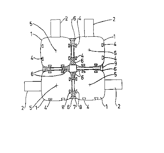
The invention will be described more closely in the
form of an example with reference to the drawing, in which
Fiq. 1 shows schematically a section of four cylinders
mounted in parallel and Fiq. 2 shows schematically a par-
tial lateral view of the interconnected cylinders.
1 designates each of the four cylinders which are

shown in Fig. 1 only with their outer contours. 2 desig-
nates the carrier means attached to the respective piston
(not shown), extendlng in known manner in a slot arranged
along the cylinder, covering and sealing the interior of
the cylinder by means of a band designated ~ in Fig. 2.
This type of cylinder is known per se and is here no part
of the invention.
In the example shown each cylinder is given a sub-
stantially square profile and has twD undercut grooves 4
lû on three sides. These grooves are preferably manufactured
at the same time as the cylinder and extend exactly in
parallel with the center axis 5 thereof. The shape of
the undercut groove 4 can of course vary and according to
the example the grooves have a profile of a substantial-
ly rectangular form.
For the interconnection of the four cylinders shownin the example eight strips 6 are used which each have in
profile a main portion 7, the opposite sides of which having
a form connecting to the outside of the cylinder. The strip
2û has further prQfiles 8 lying in a common plane, turned in
opposite directions and having a cross-sectional form cor-
responding to that of the untercut groove 4. The strip 6
has a length corresponding to that of the cylinder 1. The
strips 6 are fixed in pairs between two cylinders by means
oF screws 9, as shown in the figures.
Of course it is to be understood that an optional
number of cylinders can be interconnected in this way.
The interconnection can be made with the cylinders placed
in an optional pattern which will be easily realized.
Within the scope of the invention it will be apparent
to one skilled in the art that the cross-sectional forms
of the cylinder, the undercut grooves 4, the strips 6 and
the profiles 8 can be varied attaining the set aim.
. .~ ` : `
:: . . :
~ ' .

Representative Drawing
A single figure which represents the drawing illustrating the invention.
Administrative Status

2024-08-01:As part of the Next Generation Patents (NGP) transition, the Canadian Patents Database (CPD) now contains a more detailed Event History, which replicates the Event Log of our new back-office solution.

Please note that "Inactive:" events refers to events no longer in use in our new back-office solution.

For a clearer understanding of the status of the application/patent presented on this page, the site Disclaimer , as well as the definitions for Patent , Event History , Maintenance Fee  and Payment History  should be consulted.

Event History

Description Date
Inactive: Reversal of expired status 2012-12-05
Time Limit for Reversal Expired 2008-03-05
Letter Sent 2007-03-05
Grant by Issuance 1991-03-05

Abandonment History

There is no abandonment history.

Fee History

Fee Type Anniversary Year Due Date Paid Date
MF (category 1, 7th anniv.) - standard 1998-03-05 1998-02-19
MF (category 1, 8th anniv.) - standard 1999-03-05 1999-02-19
MF (category 1, 9th anniv.) - standard 2000-03-06 2000-02-18
MF (category 1, 10th anniv.) - standard 2001-03-05 2001-02-19
MF (category 1, 11th anniv.) - standard 2002-03-05 2002-02-19
MF (category 1, 12th anniv.) - standard 2003-03-05 2003-02-19
MF (category 1, 13th anniv.) - standard 2004-03-05 2004-02-19
MF (category 1, 14th anniv.) - standard 2005-03-07 2005-02-17
MF (category 1, 15th anniv.) - standard 2006-03-06 2006-02-17
Owners on Record

Note: Records showing the ownership history in alphabetical order.

Current Owners on Record
HYGRAMA AG
Past Owners on Record
BO GRANBOM
Past Owners that do not appear in the "Owners on Record" listing will appear in other documentation within the application.
Documents

To view selected files, please enter reCAPTCHA code :


To view images, click a link in the Document Description column. To download the documents, select one or more checkboxes in the first column and then click the "Download Selected in PDF format (Zip Archive)" or the "Download Selected as Single PDF" button.

List of published and non-published patent-specific documents on the CPD .

If you have any difficulty accessing content, you can call the Client Service Centre at 1-866-997-1936 or send them an e-mail at CIPO Client Service Centre.


Document
Description 
Date
(yyyy-mm-dd) 
Number of pages   Size of Image (KB) 
Abstract 1993-10-18 1 15
Claims 1993-10-18 1 46
Drawings 1993-10-18 1 25
Descriptions 1993-10-18 3 112
Representative drawing 2001-07-11 1 15
Maintenance Fee Notice 2007-04-15 1 172
Fees 2003-02-18 1 31
Fees 2002-02-18 1 29
Fees 2001-02-18 1 28
Fees 1998-02-18 1 32
Fees 1999-02-18 1 35
Fees 2000-02-17 1 29
Fees 2004-02-18 1 31
Fees 2005-02-16 1 28
Fees 2006-02-16 1 33
Fees 1997-02-18 1 34
Fees 1996-02-19 1 31
Fees 1995-01-19 1 36
Fees 1994-02-17 1 31
Fees 1992-08-20 1 31