Note: Descriptions are shown in the official language in which they were submitted.
CE~LUL~R DATA TELEPHONE SYSTEM
AND CELLULAR ~ATA TELEPHONE THEREFOR :
Backqround of the Invention ~:~
The present invention is generally related to
cellular telephone systems and more particularly to an -~
improved ce}lular data telephone system and cellular data
telephone for providing data and telephone services.
In the prior art callular telephone systems, ~:
telephone calls between two parties continue until their
discussions are completedO Since both partie~ are
continuously listening, either can ascertain that the
discussions have been terminated and hang up. However,
when making data calls on cellular telephone systems, the
user is not continuously listening and, as a result,
there may be long periods of time when there is no data
activity. Since tha user i9 billed for the actual air
time used, th~ user is being charged at a reIatively high
rate for such long periods of inactivity. Furthermore,
the cellular telephone system iq needlessly tied up with
data calls that could be disconnected during the long
periods of inactivity. Accordingly, thera is a need for
an improved cellular data telephone system and cellular
data telephone that maintain data calls only as necessary
to communicate data, thereby substantially eliminating
long periods of inactivity~
- . . . . : ~ -
.
~8~ 8
- 2 - CEQ0335H
Summary of the Inventlon
Accordingly, it i an ob;ect of th~ present inve~tion
to provid~ an improved cellular data telephone system and
cellular data telephone that maintains data calls only as
necessary to communicatQ data, thereby substantially
eliminating long psriod3 o~ inactivity.
It is another ob~ect o~ the present invention to
provide an improved cellular data telephone system and
cellular data telephone that are responsive to lack of
data activity for disconnecting a cellular telephone call
and maintaining the landline telephono call, and that are
r~sponsive to subsequently occurring data activity for
making another cellular telephono call and reconnecting
the landlin2 telephone call thereto.
Brief Description of tha Drawln~
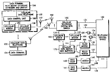
Figure 1 i~ a block diagram of a cellular daka
telephone system that may advantag~ously utilize the
present invention.
Figur~ 2 is a block diagram o~ the cellulax telephone
in the cellular data telephone 102 in Figura 1.
Figure 3 is a blo~k diagram of the c~llular data
switch 170 in Figure 1.
Figure 4 i~ a block diagra~ o~ the data control unit
in th~ c~llular data telephone 102 in Figure 1.
Figure 5 i9 a flow chart ~or tha process used by the
cellular t~lephone 108 in Fi~ures 1 and 2 for controlling
voica and data calls.
Figure 6 is a flow chart ~or tha process ussd by the
data control unit in Figure 4 ~or controlling a data
call.
Flgure 7 is a flow chart for th~ process used by the
cellular data switch 170 in Figures 1 and 3 for
controlling a data call.
, . . . .
- ~
' ' : ~; .
- 3 - ~ Z ~ 0 78 CEo0335H
Descri~tion o~ the Preferred Embodiment
In Figure 1, there is illustrated a cellular data
telephone system for providing both voice and data
telephone services to portabla and mobile callular data
telephones (CDTs) 102, 122 loca~ed anywhere in a large
geographical area. A cellular telephone system (CTS) 150
including antennas 152, 153 located at correspondlng base
site throughout the geographical area is coupled to
telephone central o~ice 130 ~or providing cellular
telephone service~ to CDT~ 102, 122. CTS 1~0 may be any
commercially available cellular telephone system such
that described ln U.S. Patant No~. 3,906,166 and
4,268,722. Cellular data switch (CDS) 170 i coupled by
cellular ~odem~ 163, 164 to CTS 150 and by telco modem~
181, 182 to telephone central office 130 for providi~g
data services to CDTs 102, 122. Telephone central office
13 0 i9 a conventional landlin~ swltching systs~ ~hat is
coupled by telephone trunk~ 131, 13~ to CT5 150:
telephone line~ 134, 135 to landline telephones 126, 127:
by t~lephana line~ 136, 137 to telco mod~ms 181, 182: and
by telephona lines 1~8, 139 to modems 146, 147.
Telephone central o~ice 130 may also be interconnected
to other conventional telephona aquipment and syskems.
Each o~ th~ CDTs 102, i22 includes a data control
unit 106, a cellular modem 162 and a cellular telephone
108 and as~oclated antenna 110, and connects to a data
terminal/per~on~l computer 104, 124 with a Xeyboard and
di~play. Data terminal 104 may bo, ~or instance, any
commercially available por~able personal computer
including a modem interface, keyboard and display.
Cellular modem 162 may be any commercially available
modem which includes error correcting capacity for
accommodating a noisy and sometimes interrupted
environment, ~uch as that encountared in cellular
telephone systems. For examplo, cellular modem 162
.. ~ .
.
.. . .
, ~
,
_ 4 ~ 8~ CEo0335H
may be a modem such as that descrlbed in U.S. patent no.
4,697,281, or a commercially available modem referred to
as the "BRIDGE" which is manufactured and ~old by
Spectrum Cellular Communications Corporation, Inc.,
Dallas, Texas.
Referring next to Figure 2, there is illustrated in
more detail cellular telephone 108 in Figure 1. Cellular
telephone 108 may include a conventional cellular
tran~ceiver 202, telephone handset with keypad 204 and
modem interface unit 206. Cellular transceiver 202
typioally accommodate~ ~ultiple ~lephone nu~bers, and in
the pre~erred environment, may be assign~d a data
telephon~ number 209 and a voic~ telephon~ num~er 210.
The data telephone number 209 is associated with modem
intQxface unit 206, whil~ the voice telephone number 210
i~ a sociated with t~lephone handset 204. When data
telephon~ number 209 i~ callad, the call i~ directed by
c~llular trans~iver 202 to ~ode~ interfac~ unit 206.
Simllarly, when voic~ telephone number 209 i9 called, the
call is direct~d by c~llular transceiver 202 to telephone
handset 204. Cellular t~lephon~ 108 may be any
comm2rcially availabl~ cellular telephone that inc1udes a
mode~ in~rfac~ unit 206. For example, cellular
telephone 108 may be a l'~YNATAC" Cellular Mobile
Telephone which is commercially available from Motorola,
Inc. and d~cribed in detail in Motorola Instruction
Manu~l 68P81070E40, together with an intelligent RJllC
interfac2 idantifi2d a~ "THE CEhLULAR CONNECTION" which
i9 commercially available from Motorola, Inc. and
de~cribed in ~urther detail in Mot~rola Instruction
Manual 68P81071E30. Copies of the foregoing Motorola
Instruction Manuals may be obtained from ~otorola C&E
Part~, 1313 East AlgQnquin Road, Schaumburg, Illinois
60196, U.S.A.
. - , ~ : . .
- .
~ . - ,
~.
_ 5 ~ C~7~ CE00335H
Referring to Fi~ure 4, there is illustrat d in more
detail da~a control unit (DCU) 106 in Figure 1~ DCU 106
include memory 302 for storing a CDS telephone number
and CDT telephone number, microcomputer 304 with internal
memory for controlli~g data communicatians between
cellular modem 162 and data terminal 104 in Figur~ 1, a
dual-tone-multifrequency ("DTMF") encoder 306 for
encoding telephone numbers and conkrol signals, a DTMF
decoder 314 for decoding DTMF telephone digits and/or
DTMF control tones, a bu~fer 312 ~or ~toring transmit
data from data termi~al 104 in Figure 1, and analog
~witcheR 308 and 310 for coupling DTMF encoder 306 and
buffer 312 ta th~ transmit data Td signal to cellular
modem 152 in Figure 1.
DCU 106 interfaces to th~ control si~nals RTS, CTS
and DCS and the data signals Rd an~ Td coupled to
c~llular modem 162 and data terminal 104. The control
signals RTS, CTS and DCS and the data signals Rd and Td
ara conventional interface ~iynals for commercially
availabl~ modem3. That is, wh~n initiating a modem
connection to data host 140, data terminal 104 sets the
r~quest o s~nd signal RT~ = 1. Assuming the data
terminal 104 is connected directly to cellular modem 162,
cellular modem 162 th~n sets the clear to send signal
CTS - 1. Thereafter, data terminal 104 may apply data to
the transmit data signal Td, coded according to the
format acc~pted by cellular modem 162. The data may
i~clude a landl~n~ telephone nu~ber q~ a desired data
ho~t 140, which ia automatically dialed by the cellular
mode~ 162. Assu~lng CDS 170 i~ not pr~sent, CT5 150
connects cellular modem 162 to the de~ired data host 140
via telephone c~ntral office 130. When khe cellular
mode~ 162 d2tect carrier from the modem 146 at the
desired daka host 140, the cellular modem 162 set3 the
data carrier d~tected signal DCD = 1. If at any time
carxier from the modem 146 is lost, the cellular
.. ~ ' '
. .
~Z8~L07~3
- 6 - CE00335H
modem 162 sets the data carrier det~cted signal DCD = 0.
All othex modems 163, 164, 181, 182, 146 and 147 have the
same control and data line~ and operate in a cimilar
manner to that de cribed hereinabove for cellular modem
162 .
Accordinq to the present in~rention, DCU 10~ is
interposed b~tween data terminal 104 and sellular modem
162 for contxolling th~ cellular telephon~ call to CTS
150 and. th~ landline telephone call to data host 140,
141. If data terminal 104 i9 inacti~re for a
predetermin~d time inter~ral, DCU 106 automatically
disconnect the cellular telephone call, while CDS 170
maintains the landline telephon~ calï. Once data is
transmitted again by data tarm~ nal 104, DCU 106
automatically place~ anoth~r cellular telephone call and
i~ raconrlected to CDS 170 and the landlina telephon~ call
via ona o~ th~ cellular mod~m~ 163, 164~
VTMF encoder 306 and DTMF d~codar 314 in DCU 106 are
utilized by microcomput~r 304 to encod~ and decode,
respectiv~ly, DrMF control tone~ and taliaphon~ numbers.
In th~ pre~erred e~odimen~ o~ DCU 106, a DTMF control
tons is used for RF disconnect of the cellular telephone
call, and another DTMF control tone i5 used for call
disconnect 9~ both the c~llular telephone call and the
landline telephone ca}l. The R~ disconnect tone and the
c:all di~connect tone are applied to the Td signal by
enabling analog switch 3G8 and disabling analog switch
310. An P~ disconnect tone or call disconnect tone from
CDS 170 are detected by DTMF decoder 314 which is coupled
to the Rd ~ignal ~rom cellular modem 1620
Micxocomputer 304 receives th2 RTS signal from data
terminal 104 and generates the RTS signal to cellular
modem 162, and likewise receives the CTS and DCD signals
for cellular modem 162 and generates th~ CTS and DCD
- .
:
.
,
. .
_ 7 _ CE00335H
()7~3
signals to da~a terminal 104 for placing and controlling
tha cellular telephone call and landline telephone call
between data terminal 104 and a desired data host 140,
141. The ~d signal from cellular modem 162 is coupled to
the Rd signal to data terminal 104, while the Td signal
~rom data terminal 104 is coupled to buffer 312, whose
output is coupled via analog switch 310 to the Td signal
to cellular modem 162.
A call is initiated by daka terminal 104 by setting
RTS = 1. Microcomputer 304 detects RTS = 1 from data
terminal 104 and sets RTS a 1 to the cellular modem 162.
In response to R~S - 1, the c~llulax mod~m 162 sets
CTS - 1 and prepares to place a cellular tel~phone call.
Microcomputor 304 detect~ CTS = 1 from the cellular modem
162, reads th~ CDS and CDT telephone numbers from memory
302, and applies the CDS telephone number to the Td
signal to cellular modem 306 via DT~F encoder 306 and
analog switch 308. Analog ~witch 310 is off at this
point in time. When cellular modem 162 detects carrier
from cellular modem 163, cellular modem 162 sets DCD = 1.
Microcomputer 304 detect~ DCD - 1 from the cellular modem
162 and applie~ the CDT telephone number to khe Td signal
to cellular modem 306 ~ia DTMF encoder 306 and analo~
switch 308.
Next, Microcomputer 304 sQt5 CTS = 1 and DCD - 1 to
data terminal 104, turns off analo~ switch 308, and turns
on analog switch 310. When CTS = 1 from the cellular
modem ~62 and CTS=l from microcomputer 304, buffer 312 is
enabled to apply data to its output. When CTS = 1 from
microcomputer 304, data terminal 104 can manually or
automatically dial the landline telephone number of the
desired data host, e.g. 141. CDT 102 is switched to a
telco modem 136, 137 by CDS 170, and telephone central
office 130 receives the dialed landline telephone number
of host 141 and switches in modem 147 and corresponding
. :.
' . ~
, ' '
.
8 lZ 8~ 07 CE00335H
data host 141, thereby completing the landline telephone
call. At this point, both the cellular telephone call
and the landline telephon@ call are connected. The :
landline telephone call continues until CDT 102 or data
host 141 hangs up, while the cellular telephone call may
be disconnected and reconnected depending upon data
activity from data terminal 104. I~ data host 141 hangs
up, CDS 170 sends a call disconnect tone to DCU 106. I~ :
data terminal sets RTS - 0, DCU 106 sends a call ~ ~
disconnect tone to CDS 170. If data terminal 104 is ~:
inactiva for a predetermined period of time, DCU 106
sends an RF disconnect tone to CSD 170 and disconnects
the cellular telephone call. When buffer 312 is full,
DCU 106 makes another cellular telephone call and is
reconnected by CDS 170 to data host 141. A detailed
description o~ the call processing by DCU 106 is providecl
hereinbelow with respsct to Figure 6.
Re~erring to Fiqure 3, there is illustrated in more
detall cellular data switch ~CDS) 170 in Figure 1. CDS
170 include~ a computer 172 for controlling cellular
modems 163, 164 and telco modems 181, 182; switch 174 :
with DTMF code .for intercoupli~g cellular modems 163,
164 and telco modems 181, 182; and buffers 176 for each
telco modem 181, 182. Cellular modems 163, 164 are
similar to cellular modem 162 in CDT 102, while modems
181, 182 may be any con~entional telephone modem. Switch
174 may of course be implemented with either
circuit-switched or packet-switched techniques. Buffer
176 atores data ~rom the Rd signal of telc~ modem 181 :
when the cellular telephone call has been disconnected
and the landlin~ telephone call is being maintained. CDS
170 may be any suitable commercially available data
switch, such as, ~or example, the data switches
manufactured and sold by Tandem Computers, Inc., 19333
Vallco Parkway, Cupertino, California, 95014, U.S.A.
'
. . . . . - . - . . . .
: .: . : , : .
, , . '.
,: . ' ' ;
.
9 ~2~1~7~ CE00335H
Computer 172 of CDS 170 detects an incoming call from
cellular modem 164 or telco modem 181 when either sets
DCD ~ ssuming cellular modem 164 is the inltiating
modem, computer 172 set~ RTS = 1 and monitors the Rd
signal to receive the CDT telephone number. If the
received CDT telephon~ number corr~sponds to that for a
call in progress, computer 172 reconnects cellular modem
164 to the corresponding telco modem 181, 182.
Otherwise, computer 172 connects cellular modem 164 to
one of the te~co modems 181, 182 not in use. If telco
modem lal is the initiating modem, computer 172 sets
RTS a 1 and connects telco modem 181 to one of the
cellular modems 163, 164 not in use. A detailed
descxiption of the call processing by CDS 170 is provided
hereinbelow with respect to Figure 7.
Referring to Figure S, there is illus~rated a flow
chart for the process used by the celLular telephone 108
in Figures 1 and 2 for controlling voice and data calls.
Cellular transceiver 202 is as~igned two telephone
numbers, a data telephone number 209 for modem interface
unit 206 and a voice telephone number 210 for handset
204. However, only one telephone number need be used in
pr~cticing the present in~ention. For example, upon
receipt o~ a telephone call from CD5 170, the user, upon
hearing the modem carrier signal, may manually switch out
handset 204 and switch in modem interface unit 206.
Entering at th~ START block in Figure 5 and
proceeding to decision bloc~ ~00, a check is madè to
determine if a data telephone number page has been
received. If so, Y~S branch is taken to blocX 508 where
the incoming call is terminated to modem interface unit
206. If not, NO branch i9 taken from decision block 500
to decision block 502. At decision block 502, a checX is
made to determine if a voice telephone number page has
'' ' ' ~ ............ .~ ~ - ,
.
.
78
- 10 - CE00335H
been received. If so, YES branch is taken to bloc~ 510
where the incoming call is terminated to handset 204. If
not, NO branch is taken from decision block 502 to
decision block 504.
At decision block 504, a check is made to determine
if handset 204 has been taken off hook to initiate a
voice call. If so, YES branch is taken to block 512
where the outgoin~ call is originated with voice
telephone number ~10. If not, NO branch is taken from
decision block 504 to decision block 506. At decision
block 506, a check is made to determine i~ modem
interface unit 206 has originated a data call. If 50,
YES branch is taken to block 514 where the outgoing call
is originated with data telephone number 209. If not, NO
branch is taken from decision block 506 to the RETURN
block to return to oth2r tasks.
Referring to Figure 6, thers is illus~rated a flow
chart far the pxocess used by microcomputer 304 o~ DCU
106 in Figure 4 ~or controlling a data call. Entering at
the START block in Figure 6 and proceeding to decision
block 602, a check is mad~ t~ determine if an incoming
call is being processed. If not, NO branch is ta~en to
block 604 wh~r~ cellular modem 16~ is connected. Next,
at block 606, the CDS telephone number is sent. Then, at
decision block 608, a check is made to determine if a
modem carrier ~ignal has been received from CDS 170. If
not, NO branch is taken to wait a predetermined time
interval for a modem carrier signal. If a modem carrier
signal is not received in the predetermined time
interval, DCU 106 returns t~ other tasks If a modem
carrier signal is received, YES branch is taken from
decision block 608 to block 610, where the CDT telephone
number from memory 302 is sent. Next, at block 612, data
terminal 104 is connected and the data, if any, in buffer
312 is sent.
'' . ':
.
.
~ 28~078 CE00335H
At block 614, the data call is connected and a data
timer is started. At this point, data terminal 104 may
dial the landline telephona number of the desired data
host, e.g. 141. During periods of data inactivity from
data terminal 104, the data timer counts down over a
predetermined time interval until expired. Next, at
decision block 618, a check is made to determine if the
data call should end. A data call may end by receipt of
a call disconnect signal from CDS 170, or by data
terminal 106 setting RTS - 0, of i~ the variable END is
set to one. If the call i3 to end, YES branch is taken
from dacision block 616 to block 642, where a call
disconnect signal i~ sent to CDS 170. Next, cellular
modem 162 is disconnected at block 644. Then, at block
646, data terminal 104 is disconnected and microcomputer
304 r~turns to oth~r task~ at the RETURN block,
I~ the call i~ to conkinue, N0 branch is taken from
decision block 616 to decision block 618, where a check
is made to determine if there has heen any data activity
~rom data tarminal 104~ Microcomputer 304 is coupled to
the Td signal from data terminal 104 for checking for
data activity. If data is b~ing transmitted by data
terminal 104, YES branch is tak~n back to block 614 to
restart the data tim~r and repeat blocks 614, 616 and
618. If data is not being transmitted by data terminal
104, NO branch is taken from decision block 618 to
decision block 620, where a check i~ made to determine if
the data timer has expired. If not, N0 branch is taken
back to decision block 616.
Returning to decision block 602, if data terminal 104
is receiving a data call, ~ES branch is taken to bloc~
636 where cellular modem 162 i~ connected. Next, data
terminal 104 is connected at block 638. Then, at block
640, an alerting signal, such as an audible tone or a
message in the data terminal display or both, is
- . . . .
.. . .
- , . . . :
: ~ .
~, , .
'
: .
.
- 12 - ~ X ~ O ~ CE00335H
generated to advise the user that a data oall has been
received. Data terminal 104 may answer tha incoming data
call by either automatically setting RTSal, or by setting
RTS=l in response to data entered by the user. Next, at
block 614, program control proceed~ as de~cribed
hereinabove.
Returning to deci~ion block 62Q, if the data timer
has expired, YES branch is taken to block 622 where an RF
disconnect is sent to CDS 170 ~or disconnecting the
cellular telephone call and maintaining th~ landline
tolephone call. According to an important feature of the
present invention, the cellular telephone call is
maintained only a3 necessary for data communications.
When data terminal 104 ha~ not transmitted data for a
predetermin~d tims int~rval determlned by the data timex,
the cellular talephone call i~ automatically disconn6!cted
by microcomputer 304.
Next, at block 624, cellular modem 162 ic
disconnected. Then, a reconnect timer is started at
block 626. During the timo period when the cellular
telephone call is disconnacted, tha reconnect timer
count~ down over a predetermined time interval until
expired. ~he Iandline telephone call is maintained at
least for the pr~determined time interval of the
reconnect timer. Once the reconnect timer has expired,
the landline telephone call is di~connected. Next, at
decision block 628, a check is made to determine if the
data call sh~uld end. If ~he call is to end, YES branch
is taken froM decision block 628 to block ~34, where the
variable END is set to one and program control returns to
block 604 to disconnect the data call.
If the call is to continue, NO branch is taken from
decision block 628 to deci~ion block 630, where a check
is mada to determine i~ buffer 312 is full. If buffer
312 is full, YES branch is taken back to block 604 to
-~ . . . , . ~ . . ,
'
: - ' :,
.
7~3
- 13 - CE0033sH
reconnect the data call. If buffer 312 is not full, N0
branch is taXen from decision block 630 to decision block
631, where a check is made to det~rmine if there has been
~ny data activity fram data terminal 104. If data is
being transmitted by data terminal 104, YES branch is
taken back to block 626 to restart the reconnect timer.
If data terminal 104 i5 not transmitting data, No branch
is taken ~rom decision block 631 to decision blocX 632,
where a check i5 made to determine if the reconnect timer
has expired. If not, N0 branch is taken back to d~cision
block 628. If the raconnect timer has expired, YES
branch is taken from decision block 632 to block 634. At
block 634, the variable END is set equal to one and
program control returns to block 604 to disconnect the
data call.
Upon returning to block 604 ~rom either block 630 or
634, according to the present invention, anoth~r cellular
telephone call is made to CDS 170. If END = 1, both the
cellular telephone call and landline telephone call are
disconnected. If END 3 0 t data terminal 104 is
reconnect~d and the data in bu~er 312 is transmitted to
CDS 170. Similarly, the data in buffe~ 176 in CDS 170 is
transmitted to data terminal 104 ~hen da~a host 141 is
reconnected. Thexeafter, data commu-nications take place
as described hereinabove with respect to blocks 616, 618
and 620.
Referrlng to Figure 7, there 1~ illustrated a flow
chart for th~ process used by the CDS 170 in Figures 1
and 3 for controlling a data call. Entaring at the
START block in Figure 7 and proceeding to decision block
702, a check is m~de to determine if a data call has been
initiated by a cellular modem 163, 164. If not, NO
branch is taken to block 704 where the initiating telco
modem, e.g. 181, is connected~ Next, at block 706, the
CDT telephone number is recei~ed. Then, a non-busy
' ' ' '', ' . '
, . ,
~8~ 7~
- 14 - CE00335
cellular modem, e.g. 164, is connected at block 70~.
Next/ at bloc~ 710, the C~T telephone number is sent to
CTS 150. CTS 150 uses the received CDT telephone number
to page the desired CDT 102, 122.
Returning to decision block 702, if a celluar modem,
8 . g. 164, has initiated the data call, YES branch is
taken to block 734 where the initiating cellular modem
164 is connected. Next, the CDT telephone number is
received at block 736. Then, at blocX 73~, a non-busy
telco modem, e.g. 1~1, is connected if the CDT telephone
number is not associated with a call in proce~s. I~ the
CDT telephone numb~r is a3soci9ted with a data call in
process to a tP.lco modem, e.g. 181, a non-busy telco
modem, e.g. 182, is not connected.
From blocks 710 and 738, program control proceeds to
block 712, where cellular modem 164 and telco modem 181
are interconn@cted by switch 174 and data, if any, in
bu~fer 176 is transmitted. Next, at decision block 714,
a check i9 made to determine i~ the data call should end.
A data call may end by r ceipt of a call disconnect
signal from CDT 104, or by telco modem 181 setting
RTS = 0. If the call is to end, YES branch is taken from
decision block 714 to block 740, where a call disconnect
signal is sent to CDT 104. Next, cellular modem 164 is
disconnected at block 742. Then, at block 744, telco
modem 181 i8 disconnected and computer 172 return~ to
~ther tasks at the REqURN blocX.
I~ the call is to continue, N0 branch is taXen from
decision bloc~ 714 to decision block 716, where a check
is made to determine if an RF disconnect signal has been
received. If not, N0 branch is taken to return to
decision block 714. I~ an RF disconnect signal has been
received, YES branch is taken from decision block 716 to
block 718, where cellular modem 164 is disconnected.
Next, at block 720, bu~er 176 is enabled and a reconnect
~ ~ ' ' ' ' ''
.
~21~07~3
- lS - CE00335H
timer is started. During the time period when the
cellular telephone call is disconnected, the reconnect
timer counts down over a predetermined time interval
until expired. The time interval of the reconnect timer
in CDS 170 is preferably set to be greater than the time
interval o~ the reconnect timer in DCU 106. In the
preferred embodiment, the time interval of the reconnect
timer .in CDS 170 is two minutes, and the ~ime interval of
the reconnect timer in DCU 106 is one minute. The
landline telephone call is maintained by CDS 170 at leact
~or the predetermined time interval of the reconnect
timer. once the reconnect timer has expired, the
landline telephone call i~ disconnected. Next, at
decision block 722, a check is made to determine if the
data call should end. If the data call is to end, YES
branch i~ taken from decision block 722 to block 744,
where the telco modem 181 is disconnected, and program
control returns to other task~ at the RETURN block.
If the data call is to continue, NO branch is taken
from decision block 722 to decision block 724, where a
check is made to determine i~ bu~fer 176 is ull. If so,
YES branch is taken to b}ock 708 to reconnect the data
call. If buffer 176 is not full, NO branch is taken ~rom :-
decision block 724 to decision block 726, where a check
is made to determine if there the CDT telephone number
has been received ~or reconnecting data terminal 104. I~
so, YES branch is taken back to block 712 to reconnect
telco modem 181 to the cellular modem 163, 164 that
received the CDT telephone number. If the CDT telephone
number has not been received, No branch is taken ~rom
decision block 726 to decision block 728, where a check
is made to determine if the reconnect timer has expired.
If not, N0 branch is taken back to decision block 722.
I~ the reconnect timer has expired, YES branch is taken
from decision block 632 to block 744 to disconnect the
data call, as described hereinabove.
.
. . . .
. . .
:
. . .
16 - ~Z8~c~78 CE0033SH
Upon returning to block 708 from block 724, acoordin~
to the present invention, another cellular telephone call
is made to data terminal 104. Data terminal 104 is
reconnected and the data in bu~fer 176 Ls transmitted to
data terminal 104. Similarly, the data in buffer 312 in
DCU 106 is transmit~ed ~o CDS 170. Thereafter, data
communicatlons take place as described hereinabove with
respect to blocks 714 and 716.
The flow chart in Figures 5, 6 and 7 pro~ide a
detailed description of the proces~ steps executed ~y the
corresponding computing circuitry o~ the cellular
telephone 108~ DCU 106 and CDS 170, reqpectively. ~y way
of analogy to an electrical circuit diagram, the flow
charts in Figures 5, 6 and 7 are equivalent to a detailed
schematic of an electrical circuit where provision of the
part values for electrical circuit componants in th~
electrical qchematic correspond~ to provision o~ computer
instructions fox blocks of the flow charts. Thus, the
coding o~ the proces~ s~p~ o~ the3e flow charts into
instructions o~ suitable commercially available computers
is a mere mechanical step ~or a routineer skilled in the
programming art.
In summary, a unique cellular data telephone system
and cellular data tolephone are responsive to lack of
activity for disconnecting a cellul-ar telephone call and
maintaining a landlin~ telephone call to a data host, and
are respon~ive to 3ubs~uently occurring activity for
making anoth~r csllular telephon2 call and reconnecting
the landline telephone call thereto. The cellular data
telephone of th~ present in~ention may be adva~tageously
utilized in any cellular telephono syste~ where data
services are desired. Therefore, while a particular
embodiment of our invention has been shown and described,
it should be understood that our invention is not limited
thereto since other embodiments may be made by those
lZ~ 37~3
- 17 - CE00335H
skilled in the art without departing from the true spirit
and scop~ of our invention. It is thus contemplated that
our paten~ encompa9ses any and all such embodiments
covered by the ~ollowing claim~.
~,,, - '
- , ~, ......... . :. . ~ ,
' .