Note: Descriptions are shown in the official language in which they were submitted.
--1--
DUAL FRONT HEADLIGHT ASSE~LY
Technical Field of the Invention
The present invention relates generally to
headlights for use in tractors and like agricultural
and industrial equipment, and more particularly to
dual or twin headlights attached to such equipment.
Background of the Invention
Tractors and other like equipment are
essential to industry. Traditionally, tractors and
other mobile equipment have had headlights installed
for a variety of reasons including movement in the
dark on public roads and for operating the equipment
without adequate natural :Light. In fact, in peak
farming seasons equipment is often operated around
the clock, thus creating the need for illumination in
the work area.
The illumination must provide quality
lighting to all 360 surrounding the equipment. The
- light provided must be well distributed in order to
avoid blindspots. Blindspots occur when an area
registering a high number of lumens is situated next
to an area of a low number of lumens. If the number
and size of these blindspots are too great the
operator is unable to monitor implement performance.
In addition to providing good quality
lighting, headlamps on farm equipment must be durable
and reliable but when necessary, easily serviced.
Also, in order to remain competitive the cost must
not be excessive.
To this end, the present invention concerns
an improved headlight assembly for agricultural or
industrial equipment which provides superior lighting.
Summary of the Invention
The present invention concerns the lighting
on agricultrual or industrial equipment and ~i
"
'
:
~2~2~3~2
particularly a dual headlight is disclosed which
provides superior lighting, in a durable, easily
manufactured, easily serviced configuration.
The dual headlight assembly has an outer
transparent lens element. The lens element may be
made of impact resistant plastic or glass or any
other suitable material. The inner surfaces of the
lens element have been cut to include corrective
prismatics. The external surfaces, in the preferred
plastic form have to be treated to ensure scratch
resistance.
The present invention further includes an
intermediate lamp reflector member defining a pair o~
generally adjacent reflective cavities. The dual
cavities of the single member provide the reflecting
surfaces for the forward and lateral lighting,
thereby minimizing the number of parts. In the
illustrated embodiment the cavities in the reflector
member are positioned to provide even distribution of
light around the tractor. The reflector members
provide apertures to support and direct the light
source.
Each lamp assembly is respectively
positioned at the rear of the adjacent reflecting
cavities. In the preferred form, the wiring for the
lateral bulb will be encased in an extension tube to
facilitate installation.
The rear enclosure member is positionable to
generally enclose a reflector member and a lamp
assembly when the reflector member is positioned
between the lens element and enclosure member. The
rear enclosure member includes 3 recesses
contemplated for receiving iso-mounts and mounting
hardware.
- , : .
3 12~313~
The rear enclosure member includes a
removable access cover for easy installation and
servicing. The removable access cover includes an
electrical coupling to capture the lamp assemblies
wiring. Once the access cover is replaced, the
coupling is available for attachment from the
exterior of the rear enclosure member.
The rear enclosure member is interposed in
the transparent lens such that the peripheral lens
lip encases the rear enclosure member. The
contacting surfaces of the transparent lens and the
rear enclosure shall be coated with an epoxy or
silicone-based adhesive or similar material, thus the
two members will be joined creating an air tight seal
to prevent moisture and dust ingress.
Other advantages and features of the present
invention will become readily apparent from the
following detailed description, the accompanying
drawings, and the appended claims.
Brief_Description of the Drawin~
FIGURE 1 is a perspective view of a front
end of typical agricultural application, illustrated
as a tractor with a representative dual headlight
installed.
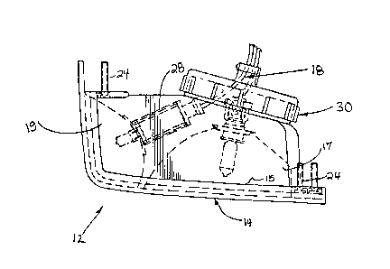
FIGURE 2 is an exploded view showing the
component parts of the dual headlight assembly.
FIGURE 3 is a top view of a fully assembled
dual headlight.
FIGURE 4 is a back view of the rear
enclosure member illustrating the access cover in its
installed position.
Detailed Descrip__on of the Preferred Embodiment
While the present invention is susceptible
- of embodiment in various forms, there is shown in the
drawings and will hereinafter be described a
: ' . ' , ~ '- ' :
- , .
- . ~ .
:. . '
-4- ~ ~ 8~ 2
presently preferred embodiment, with the
understanding that the present disclosure is to be
considered as an exemplification of the invention,
and is not intended to limit the invention to the
specific embodiment illustrated.
Referring first to FIGURE 1, therein is
illustrated a tractor 10 having a dual headlight
assembly 12 installed in the front of tractor 10
whereby the dual headlight provides illumination for
the tractor while performing a wide variety of tasks.
In accordance with the present invention,
the dual headlight 12 inc]udes a transparent dual
lens element 14 which provides protection and
dispersement for both the forward and lateral halogen
light bulbs 26. The transparent lens include
prismatics on the body inner surface of the lens
element 14. The external surfaces of the lens have
been treated with a glass resin to protect it from
abrasions and affects of hydrocarbon fuels, oils and
solvents. The lens element 14 itself is
impact-resistant plastic or glass.
The intermediate lamp reflector 16 includes
a pair of generally adjacent reflective cavities 17,
19. The cavi~ies 17, 19 are joined such that the
intersection occurs sufficiently far from the corner
of the transparent lens element 14. This
configuration allows the lateral cavity 19 to reflect
not only laterally but also directs a portion of its
light forward. The cavities 17, 19 are areanged to
distribute light evenly over a broad area.
The cavities 17, 19 shown are part of a
single lamp reflector member 16, thus reducing the
number of piece parts.
In its preferred form, the lamp reflector
member 16 is a mineral-filled polyester material to
- ~; , ' :
' ' " ~
' " ,' ~ ' .:
'
'. ~ ',
-s- ~L213~312
provide durability under exposure to ultra-violet
rays and high temperature conditions. The lamp
reflector member 16 will be coated or sprayed with a
reflective surface like chrome.
The lamp assembly 18 includes 2 halogen
bulbs 26, and the electrical sockets and wiring to
support their operation.
The lamp assembly 18 is installed in the
reflecting cavities 17, 19. The lateral cavity's
bulb installation is facilitated by an extension tube
28 which enables the assembler to easily manipulate
the bulb 26 into place through the tube 28 into the
cavity 19. After acting as a guide for the bulb, the
extension tube 28 remains in place as a protective
casing for the lamp assembly's wiring.
The rear enclosure member 20 is positionable
to generally enclose the reflector member 16 and the
lamp assemblies 18 when the reflector member 16 is
positioned between -the lens element 14 and the
enclosure member 20. In the preferred form, the
enclosure member includes 3 recesses 21 for capturing
iso-mounts 22 and mounting hardware 24. The iSQ-
mounts 22 are employed to cushion and isolate the
sensitive filaments of the halogen bulbs 26. The
iso-mounts 22 are designed to protect through the
range of velocities experienced by the vehicle.
In the preferred embodiment, the rear
enclosure member 20 includes a removable access cover
30. The access cover 30 provides a method for quick
access to repair or replace the lamp assembly 18 or
halogen bulbs 26. The removable access cover 30,
contains a gasket 34 to maintain an air tight seal
and preferably employs an eighth-of-a-turn locking
mechanism to provide quick and easy access. The
removable access cover 30 has an electrical coupling
. , .
. , ~ , , .
: ' :
- ~
. ~
' ' : '
,
-61;~3~
socket attached thereto, this preferred feature
improves durabilit~ and prevents loss when access
cover 30 is removed for servicing~
The said rear enclosure member 20 is
positioned in the transparent lens 14 such that the
lens peripheral lip 15 encompasses the rear enclosure
member 20. The contacting surface of the transparent
lens lip 15 and the rear enclosure member 20 are
sealed with silicone-based adhesive or epoxy. Thus,
the two members, ~0 and 14 are joined, creating an
airtight seal to prevent moisture and dust ingress.
From the foregoing, it will be observed that
numerous modifications and variations of the present
dual headlamp assembly can be effected without
departing from the true spirit and scope of the novel
concept of the present invention. It will be
appreciated that no limitation with respect to the
specific embodiment disclosed herein are intended or
- should be inferred. The d-isclosure is intended to
- 20 cover by the appended claims all such modifications
as fall within the scope of the claims.
- : ,' - . ~ . , -:
.
: