Note: Descriptions are shown in the official language in which they were submitted.
93~1
707~
Title: COPY ACCESSORY FOR AN INSTANT CAMERA
BACKGROUND OF THE_INVENTION
The invention relates to a photographic copying
accessory and, more particularly, one for use with
photographic apparatus of the self-developing type for
providing photographic reproductions of photographic
prints and the like.
Various apparatus exist which facilitate the
copying of photographs and other planar images. It is
desirable to obtain high quality photographic reproduc-
tions in the least expensive manner.
One type of copying apparatus is characterizedby a camera enclosed permanently within the photocopying
apparatus. This tends to be expensive, and the high cost
factor~ is a significant drawback in the amateur camera
market. Aside from this drawback, such a photocopying
apparatus is relatively heavy and more cum~ersome to use
than~is desirable. Furthermore, there is provlded a
separate artificial illumination system which must be
compatible with the camera used. Examples of such
20 apparatus are disclosed in U.S. Patent Nos. 3,065,667;
4,200,392; and 4,300,827.
Another amateur photocopying apparatus is an
accessory which releaseably cooperates with a camera.
This accessory may be less expensive than the apparatus
noted previously. Such accessory when coupled with a
--1--
:
7074
~;~8~93~
camera of the instant developing type facilitates
reproduction of prints in a relatively quick and easy
manner. Accessories of this type are described in U.S.
Patent Nos. 2,866,380, 3,697,175 and 3,653,760. To
5 function in a manner providing acceptable prints, these
apparatus must provide exposures in a manner which allows
faithful reproduction of prints. For copying reflection
type prin~s, such as described in the first two patents,
an internal source of artificial illumination is provided
l0 in the accessory itself which constitutes an added
expense. For copying transparencies, the light source of
the camera is utilized, such as described in the last
noted patent.
The last noted accessories are also limited
15 insofar as they cannot be used with cameras having
automatic ranging systems and fill flash exposure systems
such as that described in U.S. Patent No. 4,526,444.
? SUMMARY OF THE INVENTION
In accordance with the present invention, there
20 is provided an improved photographic accessory for use
with photographic apparatus of the self-developing kind,
especially the more sophisticated versions.
This accessory is for photographically copying
object~s, particularly photographic prints, with reflected
25 light by a photographic apparatus using-its own source of
artificial illumination.
In an illustrated embodiment, the accessory com-
prises a housing assembly, and mounted on the assembly is
a lens assembly. The housing assembly has means for
30 defining an aperture within the field of view of the lens
assembly and for positioning the object to be
photographically copied. The lens assembly provides a
preselected ratio of the size of the image with respect to
the copy so that it can properly size the image of the
35 subject at the assembly aperture to the image area of the
--2
7074
~2~93~)
film format used in the photographic apparatus. The
housing assembly includes means for removably receiving
and supporting the camera such that the taking lens of the
camera and the lens assembly are substantially optically
coaxial. Means are provided for functionally interfacing
with the exposure control means of the camera and the lens
assembly. For illuminating the object to be copied there
is provided an illuminating means which serves to define
light paths so that the object can be illuminated evenly
by the illuminating source of the photographic apparatus.
In a preferred embodiment the illuminating means
includes a system of mirrors which are arranged with
respect to each other and the source of illumination so
that the object to be photographed is generally uniformly
lS illuminated by such source.
In another illustrated embodiment the interfac-
ing assembly includes optical means associated therewith
which diverts a portion of the illumination from the
camera source to the exposure control system of the
camera. This optical means is arranged so as to increase
termination of exposure by the automatic exposure control
means. This provides a better exposure of the object
being copied. In such an embodiment, the optical means
comprises of a generally elongated optical member having
surfaces arranged to transmit light by total internal
reflection between the artificial illumination and the
exposure control means.
In another illustrated embodiment the optical
accessory includes a window which receives in overlying
relationship thereto the sonar transducer of the
rangefinder of the photographic apparatus. Such window
facilitates automatic focusing of the taking lens. The
housing assembly also inclùdes means for redirecting the
acoustic energy to avoid having the energy creating an
interference pattern that could contribute to range
misinformation.
7074
L93~
In another illustrated embodiment the housing is
provided with a movable top cover movable between a closed
position and an open position. When in the closed
position the cover covers the lens assembly, the
illuminating cooperating means as well as the interfacing
means. ~hen in the open position the cover allows the
photographic apparatus to be supported in fixed
relationship to the interfacing means and at the same time
assist in properly maintaining the photographic apparatus
such that its taking lens is optically coincident with the
lens assembly.
Among the other objects of the invention are
therefore, the provision of an accessory for use with a
photographic camera of the instant developing type which
converts the camera into a copying camera; the provision
of an accessory which facilitates easy and correct
installation of the photographic apparatus; the provision
of an accessory of the above type which is inexpensive and
easily operated insofar as there are no operator steps
necessary other than mounting and shooting; the provision
of an accessory of the foregoing type which is compact and
portable; the provision of an accessory for a photographic
apparatus of the above type which is simple and easy to
fabricate; and, the provision of an accessory apparatus
for use with a photographic apparatus of the above type
which takes reflection type photographs using the
illumination source of the photographic apparatus.
The above and other objects and further scope of
applicability of the present invention will become appar-
ent with the following detailed description when read inconjunction with the accompanying drawings wherein like
reference numerals indicate like structure throughout the
several views.
--4--
- .
.
70~4
~RIEF DESCRIPTION OF THE DRAWINGS
FIG. 1 is a perspective view of a photographic
accessory made in accordance with the principles of the
present invention and shown in a closed condition;
FIG. 2 is a perspective view showing the photo-
graphic accessory in an open position wherein a photo-
graphic apparatus of the instant developing type is
mounted therein;
FIG. 3 is a cross-sectional view taken along
section line 3-3 appearing in FIG. 1 and looking in the
direction of the arrows;
FIG. 4 is a cross-sectional view taken along
section line 4-4 appearing in FIG. 3 and looking in the
direction of the arrows;
FIG. 5 is a exploded perspective view showing
some components of the photographic accessory;
FIG. 6 is an enlarged fragmentary view showing in
cross section certain components of the housing assembly
of the photographic accessory;
~0 FIG. 7 is another enlarged fragmentary view
showing in cross section certain features of the present
accessory which receive and position the photographic
print to be copied;
FIG. 8 is a bottom view of the accessory of the
~5 present invention with a photographic print mounted there-
in; and,
FIG. 9 is a perspective view of the photographic
apparatus of the present invention for which the photo-
graphic accessory of the present invention is fabricated
to cooperate witho
DETAILED DESCRIPTION
FIGS. 1 - 8 depict the improved photographic
accessory 10 of the present invention. The accessory 10
is easily and inexpensively fabricated from moldable
plastic.
7074
The accessory lO is adapted ~or use particu]arly
with ~ self-developing camera 12 of the type described in
U.S. Patent No~ 4,526,444 and shown in FIG. 9
As the camera 12 does not form an aspect of the
present invention a detailed description thereof will be
omitted. However, those portions of the camera which are
necessary for purposes of understanding the photographic
accessory lO will be set forth.
The camera 12 shown in FIG. 9 includes a first
housing portion 14 and a second housing portion 16, the
latter of which has one end attached pivotally to the
former. The first housing portion 14 has a leading end
wall 18 which includes an outwardly and rearwardly
slanting portion 20. The slanting portion 20 terminates
before a component module 22 of the camera, the latter of
which is mounted on the second housing portion 16. An
elon~ated exit slot 23 extends along the width of the
leading wall 18 and provides an exit for the photographic
film unit ejected from the camera 12 by a film advancing
means (not shown).
The front face of the module includes a
sonar-type range finder 24, a taking lens assembly 26, a
j photocell assembly 28, a viewfinder window 30 and a source
; of ar~ificial illumination, such as electronic strobe 32.
As shown in FIGS. l - 4 and 8, the copy
accessory lO includes Eront and back housing portions 34
and 36. The front and back portions 34 and 36 are
interconnected at the top by an interface plate or
assembly 38 and at the bottom by a base assembly 40.
A top cover 42 is pivotally mounted by arms 42a
to the front stand 34. The top cover 42 is movable
between a closed position as shown in FIG. l and an open
position as shown in FIGS. 2 and 3. When in the open
position, the cover 42 covers the interface plate 38.
When the top cover 42 is in its open or operative
707~
~2~3~
position, it serves not only to maintain properly the
camera 12 in a desired stable orientation/ but facilitates
passage of the film unit 44 (FIG. 5) from the camera 12
following comple~ion of a photocopying cycle. In this
latter regard, it will be noted that the cover 42 is
formed such that a space 46 extends along the length of
the exit slot 23 when the cover is erect. Accordingly,
the film unit upon exiting the exit slot 23 can fall
downwardly therefrom.
In The front stand 34 defines an opening closable
by a loading door 48. The loading door 48 includes a pair
of opposed pintles 4~ (one of which is shown) which are
received by and between the front stand 34 and the base
assembly 40 (FIGS. 3 and 6). The manner of connection
allows the loading door 48 to move pivotally between open
and closed positions; such as shown in FIGS. l and 2. The
loading door 48 allows articles to be placed in the
accessory lO at an image area defined by the base assembly
40. When the loading door 48 is opened, a user can insure
that the film unit and/or the other material which is to
be copied are properly positioned. The door 48 includes a
flexibly, resilient latch 50 which facilitates the
releaseable latching.
The base assembly 40 includes a generally planar
~5 mask 54 which is attached at respective corners to the
front and back stand members 34,36. As shown in FIGS. 4
and 8, the mask 54 defines a generally rectangular opening
or image area 56 and an overhanging print retaining lip
58. The lip 58 cooperates with the generally planar
aluminum base 60 to form grooves 62 which slidably receive
a film unit 44. The film units ~4 will slide such that
their longitudinal edges cooperate with the grooves 62
formed by and between the mask 54 and the base member 60.
These grooves 62 are dimensioned such that they encompass
the marginal edges of each film unit. In this manner,
7074
~3~33()
image area of each film unit to be photographically copied
is suitably positioned such that the film unit's borders
are not within the image area to be copied. Furthermore,
the base member 60 includes a centrally positioned finger
slot 64 which facilitates insertion and removal of the
film unit 44 into and from the grooves 62. The base 60
when attached by suitable means, not shown, to the mas~ 54
define means for properly positioning the film unit 44 in
a generally planar orientation. Having the print to be
copied in a planar orientation facilitates greatly the
photocopying thereof.
The interface plate 38 is attached, by threaded
members, to the front and back stand members 34 and 36.
The interface plate 38 cooperates with the camera 12.
One important aspect of the interface plate 38
is to insure that the optical system of the self-develop-
ing camera 12 is optically correctly aligned. Towards
that end, there is provided a pair of opposed and
upstanding retaining fingers 64. These serve to laterally
position the camera 12. Integrally formed on the
interface plate 38 are mounting pads 66 which are
constructed and arranged with respect to each other to
properly mount and support the camera 12 in a desired
stable' orientation.
As best shown in FIG. 3, the top cover 42 has
formed on the inside surface thereof a generally smooth
and rounded camera engaging projection 68. The projection
68 is dimensioned to engage the underside surface of the
camera 12 and urges the top surface of the camera into
firm engagement with the inclined retaining surface 70.
By inserting the camera ]2 into the accessory 10 (FIGS. 2
and 5) the lateral retaining fingers 64, mounting pads 66,
projection 68 and retaining surface 70 cooperatively func-
tion to insure that the optical axis of the lens assembly
26 is substantially coaxial with the optical axis of the
lens assembly 72 of the accessory 10.
7074
s3~
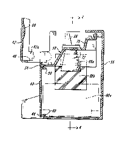
Formed in the interface plate 38 is a transducer
window opening 76, a lens assembly opening 78, a photocell
window 80 and a strobe window 82. Positioned beneath the
top surface of the interface plate 38 is a sonar baffle
plate 84 which has the configuration depicted in FIGS. ~
and 5. The purpose of the baffle plate 84 is to redirect
the path of the sound waves emitted from the camera 12.
By redirecting the sonar ranging waves, there is virtually
no likelihood of damaging interference waves being
established by three-dimensional objects positioned in the
image area 56. Interference waves might cause the sonar
rangefinder to cause the camera lens to misfocus.
Although the baffle plate 84 is shown, it is to be
understood that the present invention can function without
such a baffle plate. Given the fact that the distance
between the sonar rangefinder and the bottom of the
accessory 10 is relatively small the rangefinder 24 will
cause the lens system 26 to focus on its close focus
position.
The lens assembly 72 may be a close-up lens. In
other words, the lens assembly 7 2 provides a slight
magnification of the image area 56. Any print image in
the image area 56 will be slightly enlarged at the camera
focal plane. Thus, the image size-object size ratio is
greater than 1. This is done for purposes of overcoming
slight misalignments between the optical axes of the lens
system 26 and the lens accessory assembly 72 which would
result in a photocopy including more than the image area
56. Toward the end of achieving this, a close-up lens
system 86 provides for the desired magnification. The
close-up lens 86 is housed within a truncated lens housing
87 which is suitably secured to the interface plate 38. A
portion of the lens housing 87 is accommodated by the
opening 78. The optical axis of the lens assembly 72 is
centered with the image area o~ the print to be
_9_
7074
photographed. The lens assembly 72 i5 sufficiently
corrected for any aberrations which might occur in the
kind of photocopying situation contemplated. The lens
assembly 72 does not, per se, form an aspect of the
present invention. Therefore, details thereof have not
been set forth. However, the lens magnification is for
purposes of correcting for slight misalignments of the
camera lens 26 with respect to the lens assembly 72.
~isalignment may arise from a number of factors including
tolerance differences between cameras and accessories.
Another aspect of this invention is the illumin-
ating means of the photographic accessory 10. The illumi-
nating means includes a plurality of mirrors 88a,b and c.
The mirrors 88a-c are arranged with respect to each other
lS so as to establish folded light paths by which the strobe
light can be directed to the film unit 44 in a generally
uniform manner.
As best seen in FIG. 4, the mirror 88a is firmly
secured to an inclined surface of the interface plate 38.
Attached by suitable mirror mounting pads 90 is a second
mirror 88b which is housed within the handle portions 92
of the front and back stand members 34 and 36. The handle
portions enhance portability of the accessory 10~ The
mirror 88c is positioned on the opposite side of the image
area 56 and is mounted by the mounting pads 90 in such an
orientation that it reflects the light from mirror 88b
onto the image area 56. A ray trace of the strobe ligh~
~rom the strobe 32 is shown by the ray tracing lines 94.
The mirrors 88a-c are arranged so that they generally
uniformly illuminate the area 56 by providing light from
both mirrors 88b and 88c. Thus, this particular
arrangment is particularly advantageous since it only
requires a single source of illumination to uniformly
illuminate the print or other objects in the image area.
Also, the mirrors 88a-c are arranged such that they direct
--10--
7074 ~ 3
the light at relatively shallow angles to the image area
56. This is to overcome the problem of specular
reflection inherent in photocopying, especially copying
photographic prints having a somewha~ reflective
transparent layer thereover.
Reference is made to FIGS. 2, 4 and 5 for
illustrating an improved optical means for enhancing
exposure of the camera 12 for photocopying purposes. The
optical means compensates for the fact that the automatic
exposure camera 12 will be taking photographs in an
otherwise compact and light-tight compartment with the
photocell's field of view being obstructed partially by
the lens assembly 72. Because of this obstruction, the
photocell assembly 28 will sense a fraction of the light
on the print. Accordingly, the exposure control system
would cause the exposure interval to terminate too later
As a result, the print photograph would be overexposed,
wherein the image is burnt out.
In this embodiment, the optical means includes
an optical member 96 or transparent wedge. The optical
member 96 is defined as a generally flat and rectangular
piece of transparent plastic. At opposite ends of the
member 96 angled surfaces 98a,b are formed which are
respec~tively placed in overlying relationship to the
strobe 32 and the photocell 28. The angles of the
suraces 98a,b are selected so as to effect transmission
of light from surface 98a to surface 98b by means of total
internal reflection. In essence, a light-pipe is created
between the strobe and photocell. The surfaces 98a,b are
laterally offset with respect to each other. This is done
so that the surface 98a is in overlying relationship to
the area of maximum strobe output while the other surface
98b is positioned in overlying relationship to the
infrared portion of the photocell assembly 28. With
camera 12, the photocell assembly 28 is responsive
--11--
~074
3~0
primarily to infrared scene radia~ion during strobe
firing.
It will be appreciated that the amount of light
transmitted to the photocell assembly 28 from the strobe
32 should be within the boundaries effective to provide a
good exposure of the print to be copied. Although the
illustrated embodiment discloses use of angled surfaces
98a,b to effect transfer of light, it is well within the
spirit of the present invention to employ other approaches
to simulate and/or enhance such transfer. The configura-
tion of the optical member 96 could vary provided it
transfers the requisite amount of light from the strobe to
the photocell to achieve proper exposure.
Operation of the accessory 10 is believed
obvious from the foregoing description. Such an accessory
10 facilitates the photocopying of a wide variety of sub-
jects. For instance, the accessory 10 is especially
effective for making prints of diffusion transfer photo-
graphic prints in an inexpensive and reliable manner. By
lifting the cover 42 and mounting the camera 12 on the
interfaee plate 38, the camera 12 is simply and easily
converted to a photocopy camera. The accessory 10
requires no special operation or adjustment other than the
previo~sly noted mounting. Since the operator merely has
to press a button on the camera 12 for effecting exposure
there are no special operator steps other than the noted
mounting and shooting. The construction of the accessory
10 is compact, relatively inexpensive and easily portable.
Not only can the accessory 10 be used to copy photographic
prints, but can copy other planar material (e.g. maga-
zines, books, etc.) visible through the image area 56. As
noted previously, three-dimensional objects, such as
jewelry can be photographed when placed at the image area
56 in the exposure compartment formed inside the aceessory
10.
-12-
7074
~8~93~3
Since certain changes may be made in the above-
described accessory without departing from the scope of
the invention herein involved, it is intended that all
matter contained in the description or shown in the accom-
panying drawings be interpreted as illustrative and not ina limiting sense.
-13-