Note: Descriptions are shown in the official language in which they were submitted.
S U M M A R Y :
Control Device for Electrlcal Wheelchairs or the Like.
The invention relates to a control device of
the type stated in the higher concept of claim 1, for electrical
wheelchairs or the like. Such a control device is frequently called a
"joy stick".
Through the company document "Wheelchairs and
Rehabilitation Devices" [/in German/] of the firm MEYRA, D-4925,
Kalletal 1, August 1984, page 79, and the wheelchairs supplied by this
same firm, a control device of the type concerned has become known, in
which the mechanical-electrical adjustment elements consist of
potentiometers, the axes of which~ displaced by 90~, lie in a plane
which is essentially vertical to the direction of the control lever.
The end of one arm of a U-shaped bracket is attached to the axes, in the
central part of which bracket there are apertures, into which the one
arm of the control lever, which is constructed with tw~ arms~ engages.
.
Upon moving the con~rol lever in the direction of the one aperture, the
other U-shaped bracket, and thereby the potentiometer connected with it,
is moved, and vice versa, wher0by, of course, all possible intermediate
forms of movement are possible, so that a practically 4-quadrant control
device is formed.
The central parts of the U-shaped bracket~ in
which the apertures are located, are, corresponding to the movement path
of the control lever, and in regard to the swivelling pivots of the
same, constructed in a curved manner. Production is thereby
complicated, particularly the production of the aperture positioned in
this curved part. Furthermore~ an additional pivot bearing is provided
on the end of the arm of the U-shaped bracket which is turned to the
potentiometer. This also represents an additional construction expense.
8ecause of the U-shaped bracket~ the construction height is relatively
great, which is therefore a partiGular disadvantage, since a control
device of the type concerned~ for use in a wheelchair, must be
accommodated in, or in the area of, the armrest of the wheelchair.
The task which forms the basis of the invention
is that of creating a control device of the type concerned, which does
not have the disadvantages of the known control device, which is
therefore simple and inexpensive in construction, and which has a low
construction height.
~,7~
The task which forms the basis o~ the invention
is solved through the fact that connector link gearings are used as
mechanical transmission devices. In such a connector link gearing,
there results a low construction height, with, at ~he same time, merely
average expense. The control lever engages, in such a type of connector
link gearing, in an entirely simple manner, with a link connector, which
abuts on the control lever, and, during movements which do not take
place along the contour of the connector link, is moved, whereby this
movement ;s transferred to the mechanical-electrical adjustment element.
The connector link and its guide can be produced in a very simple
manner, so that low production costs result. Furthermore~ the
construction height is also very low.
In accordance with on@ possibility of execution
of the invention, the connector link gearings can have two slide units,
which are held in a displaceable manner in the same direction, and each
have, reciprocally inclined to their direction of displacement,
connector link apertures, in which the control lever engages, whereby
the slide units are connected with the mechanical-electrical adjustment
elements. Through the fact that the slide units are displaceable ;n the
same direction, practically the same guide can be used for them, which
entails simplicity of construction. The connector links can be produced
in a very simple manner and very precisely, for example, by stamping
them out, if the slide units are formed from plates.
A 11
Through the inclination of the connector link
apertures, the transmission function can be varied within very wide
rang~s, so that corresponding possibilities for variation in the control
characteristics of the control lever result. The connector link
apertures can be inclined by 45 to the direction of displacement,
although other angles are also possible, however, through which a
different control characteristic results during deflections of the
control lever in various directions. One particular advantage in the
use of the connector links consists of the fact that they make possible,
not only through their inclination, but also through their curved shape,
very different control characteristics. The connector links or the
connector link apertures can therefore be curved. Particularly suitable
in this connection is a curvature which is centrally symmetrical to the
center, and which is defined by the resting position of the control
lever, so that, in fact, a characteristic which is non-linear, but is
still~ however, symmetrical to both directions of deflections, is
provided.
One particularly suitable form of construction
of the slide units constructed as plates with connector link apertures
is stated in claim 6. The guidance of the plates takes place in this
in an entirely simple manner by means of guide apertures lying opposite
to one another in the plates, into which a guide pin common to both
plates engages, which therefore guides both plates at the same time.
A~ially to the guide pin, support shoulders which hold and guide the
plates on the pins movably in their position are naturally necessary.
~ ~B~
These support shoulders and the plates themselves can be produced from
suitable material, preferably ~rom plastic, which requires no
lubrication, so that a construction which is nearly completely free of
maintenance and wear is provided.
In accordance with one further construction in
accordance with claim 7, a bushing extends through the crossing
apertures, which bushing abuts, with at least one flange, on one of the
plates, whereby the control lever, with an at least partially spherical
part, engages into the bushing. Through this fact, a coupling of the
control lever with ~he connector link aperture which is free of
clearance is attained, although the control lever, during deflections
vertical to the slide units, undergoes a movement, since the contact
point of the control lever moves on a circular path, while the slide
units or plates move on a secant to this circular path.
The plates forming the slide units can lie
tightly, and preferably directly, on top of one another. This is
constructively suitab1e, and therefore possible, because the guide
forces vertical to the plates, and thereby the support forces of the
plates on one another, are very slight.
The use of slide units for the connector link
gearing makes possible a very suitable further development, since the
arrangement of lateral projections or depressions on the slide units,
which can cooperate with an activating element of a switch, is possible.
. . . ...
13
Such a switch serves, in the case of a ~hee1chair, to carry out certain
switching processes, if the individual operating it releases the control
1ever. In accordance wi~h a ~urther development of this form of
execution, depressions are thereby provided on both slide units, whichs
in the resting position of the control lever, align with one another in
such a manner that the switch is only activated in the resting position
of the control lever.
The mechanical-electrical adjustment elements
can, in a very s;mple manner, be flat sheet resistors or flat sheet
potentiometers, which are connected with the slide units directly or
indirectly by means of small transmission studs. Through this fact
there result completely linear control characteristics, ~hile the
construction height is at the same time particularly low. For
mechanical-electrical adjustment elements, how~ver, rotary resistors or
electrical adjustment elements can also be used, to the axes of which
one lever each is attached, which engage with the studs each positioned
on the slide unit. The position of the rotary resistors or rotary
potentiometers is thereby completely free, provided that its axis
proceeds vertically to the direction of displacement of the slide unit.
This form of execution thus makes possible a selected arrangement of the
rotary resistors or the rotary potentiometers, particularly such as one
in which the construction height is very low. The lever necessary for
the rotary movement of the rotary resistors or rotary potentiometers is
advantageously a prong, in which a stud engages on the slide unit.
Naturally, a conversion of the linear movement of the slide unit into
36
14
the rotational movement of the rotary resistors or rotary potentiometers
is also possible by means of other transmission gearings, such as, for
example, by means of a crank drive. The adjustment elements can also
operate inductively.
The invention will now be illustrated in
further detail by means of the diagrams.
Figure 1: Depicts a vertical section through an example
of execution of a control device in accordance
with the invention;
Figure 2: Depicts a lateral view II of Figure 1;
Figure 3: Depicts a view III from below in Figure 1,
whereby the lower cover cap is omitted;
Figure 4: Depicts individually a lower slide unit in
Figure 1; and:
F;gure 5: Depicts indiv;dually an upper slide unit from
Figure 1.
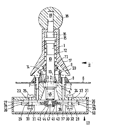
A control lever (1) has a ball and socket joint
(2). the spherical part (3) of which rests on the control lever (1)3 and
the stationary part (4) of which is held on the plate (6) by means of a
housing part (5), with which the entire control device can be attached
to the arm rest of a wheelchair, for example, by means of screws. The
housing part (5) is held by means of screws (7), which simultaneously
support a stop ring (8), the stop edge (9) of which limits the
deflection movements of the control lever (1).
On one upper arm (10) of the control lever (1),
which is constructed as a two-armed le~er, a bushing (11) is positioned
in a displaceable manner, which is pressed against a disk (14) with its
lower edge (13) by a pressure spring (12), which disk is held on the
upper surface of the plate (6) by the stop ring (8). The pressure
spring (12) is supported on a screw ring (15), which can be moved on a
threading (16) of the upper arm (10), in order to be able to adjust the
pressure force of the spring (12) and thereby the support of the lower
edge (13) on the disk (14), and thus the restoration force of the
control lever (1) as well, which is conditioned thereby. The upper arm
(10) with the pressure spring (12) is covered by a cap (17), which is
held by a sphere (18), which is firmly screwed on by means of a
threaded end (19) of the upper arm (10). Between the bushing (11) and
the stop ring (8), there extends a sealing part (20).
The housing part (5) has a round flange (21),
in which there are positioned holes (2Z and 23) lying diametrically
opposed to one another. through which the screws (24 and 25) extend,
, ' , ~ .
16
and which hold disks (26 and 27) and bushings (Z8 and 29), as ~ell as
disks (30 and 31), which are all drawn against the flange (21) by means
of the nuts (32 and 33).
Between the disks (26, 27 and 30, 31), two
plates (34 and 35) are conducted in a displaceable manner, whereby the
bushings (28 and 29) slide in the apertures (36 and 37) in the plates
(34 and 35) in a manner which is free from clearance. The construction
of the plates (34 and 35) and the arrangement of the apertures (36 and
37) can be distinctly seen from Figure 3. The plates (34 and 35) are
eherefore conducted in the direction of the apertures (36 and 37) in an
easily displaceable manner and free from clearance. In the area of the
bushing (29), apertures (38 and 39) are located in the plates (34 and
35), within which the bushing (29) slides in a manner free of clearance.
Between the apertures (36, 37), on the one
hand, and (38, 39), on the other hand, there is located, in the plate
(35), a connector link aperture (40) which is inclined by 45 in the
direction of displacement, and, in the plate (36), a connector link
aperture (41). As can be seen from Figure 3, in connection with Figure
1, a bushing (42) extends through the crossing connector link apertures
(40 and 41), which bushing is so dimensioned that it can slide into the
connector link apertures in a manner ~ree of clearance. There is
located on the bushing (42) a flange (43), which abuts on the plate (34)
. -- .
~9~
in a sl;ding manner. On the other side of the bushing (42)) a disk (44)
is slid onto this, which abuts on the plate (35), and is held on the
bushing by means of a security retaining ring (45).
As is evident from Figure 1, there is located
on a lower arm (46) of the control lever (1) a partially spherical part
(47), which snugly engages in the interior of the bushins (42) and
is therefore in a position to transfer the movements of the control
lever (1) to the bushing (42) in a manner which is free of clearance.
There is located on the plate (35) a stud (48),
which engages without clearance in the opening of a prong (49), which is
attached as a lever on an axis (50) of a potentiometer (51), so that,
~uring the displacement of the plate (35) and thereby of the stud (48),
the lever (49) is swivelled, and the axis (50) of the potentiometer (51)
is turned.
In the same way, there is located on the plate
(34) a stud (52), which engages in the free opening of a lever (53)
which is constructed as a prong, which lever is attached on an axis t54)
of a potentiometer ~55). In the range of movement of the stud (52), the
plate t35) has a recess (56), so that the stud (52) can be moved without
disturbance from the plate (35).
18
As evident from Figur~s 4 and 5, there is
located on one edge (57J of the plate (35) a depression (58), while, on
one edge (59) of the plate (34), the depression (60) is located. These
depressions ~58, 60) cooperate with a control roller (61) on an
activating arm (62) of a microswitch (63). In the position depicted in
Figure 3, the control roller (61) rests directly in the depressions (58,
60) lying directly above one another, so that the microswitch (63),
depending on its form of execution, is closed or opened, while it opens
or closes when the p1ates (34 or 35) move out.
The edges (64 and 65) ly;ng opposite one
another have longitudinally extending depressions, which cooperate with
a control roller (66) on an activating arm ~67) of a microswitch (68),
whereby the activation of this microswitch (68) is e~fected in the final
displacement position of the plates (34 and 35).
As is particularly evident from Figure 1, the
entire part lying below the plate (6) is partially protected against
moisture and dust by the housing (5), but is completely so protected,
however, by a covering cap (69) placed on the flange (21).
As can be seen from Figures 1 and 3, upon
activating the control lever (1) in the direction of the connector link
aperture (40), the bushing (42) is pressed against the edge of a
connector link aperture (41), so that the corresponding plate (34) is
displaced, and the axis (54) of the corresponding potentiometer (55) is
~986
rotated through the stud (52) by means of the 1ever (53). If the
control lever (1) is moved in the direction of the connector link
aperture (41), the bushing (42) presses against the lateral edge of the
connector link aperture (40)~ so that the corresponding plate (35) is
dis~laced, and the axis (50) of the potentiometer (51) is turned by
means of the studs (48) and the lever (49). During movements in other
directions, both plates (34 and 35) are moved more or less
simultaneously, so that the potentiometers (51 and 55) are displaced
more or less correspondingly. The control lever (1) can also be
activated by foot, rather than by hand.