Note: Descriptions are shown in the official language in which they were submitted.
~L~82227
Case 6156/B158(2)
GAS DISTRIBUTION PLATE FOR FLUIDISATION
-
The present invention relates to a fluidised bed apparatus
comprising a fluldisation grid (i.e. a gas distribution plate) with
a plurality of surfaces havlng different slopes, this fluidisation
grid being in communication with a wlthdrawal chamber, snd also the
application o this apparatus to various processes comprising the
use of a fluidised bed.
It is known that a solid in powder form is brought into
fluidisation in a rising gas stream when the whole of the solid and
gaseous phases form a dense and homogeneous bed possessing the
apparent characteristics of a fluid. Fluidising a solid ln powder
form is generally an easy operation, when the speed of the gas
stream i8 adapted to the particle size of the powdery solid. It
requires regular distribution of the fluidising gas in the bed of
fluidised solid. This distribution is commonly obtained by a
lS fluidisation grid arranged in the bottom part of the fluidised bed
apparatus.
Such a fluidisation grid is a device provitet with apertures
and the gas stream introduced beneath the grid has to be distributed
evenly through these apertures.
2~ In numerous Industrial applications employing the fluidisation
technique, the fluidisation grid is provided with an outlet
permitting of the discharge of the manufactured products, either
continuously or at the ent of the operation if the process is
discontinuous. This is the case in particular for processes of
granulation of solid substances in powder form, such as chemical
, 1 ~
,..
'
1282ZZ7
fertilizer~, cement, lime, glags powder, abra~ive substances,
mineral or organic substances, combustlble ~ubstances, food products
or pharmaceutical product~. In other processes employing the
fluidisation technique, it is important to be able to discharge
rapidly from the fluidised bed reactor agglomerates formed
accidently by sticking or melting of several solid particles; in
view of their size, these agglomerates cannot be maintained in
fluldisation and are deposited on the fluidisation grid; at the end
of a time of varying length the accumulation of these agglomerates
may thus bring about the clogging of the apertures in this grid.
In particular agglomerates may appear in processes of
coal gasification by fluldisatlon. In this case it is essential to
be able to e~tract from the fluidised bed reactor the coal ash which
is more or less softened by the effect of the temperature and which
has a tendency to bring about sticking of the granules. Thus these
ashes must be discharged as rapidly as possible before the
agglomerates of ash reach troublesome dimensions.
Agglomerates may also form in processes of polymerisation or
copolymerisation in the gas phase of ethylenically unsaturated
monomers, when operating in a fluidised bed apparatus in the
presence of one or more solid catalysts or initiators leading to the
formation of particles of polymer which enlarge as the reaction
proceeds, these polymer particles being maintained in the fluidised
condition by a rising gas stream containing the said ethylenically
unsaturated monomers. As the polymerisation or copolymerisation
reaction is exothermic, hot spots may be produced and lead, when the
locally prevalling conditions in the fluidised bed allow, to a
softening of the polymer particles or copolymer particles and to the
formation of agglomerates.
It is known from European Patent Application No 0088655 to
polymerise or to copolymerise alpha-olefins in a fluidiset bed, in a
fluidised bed reactor comprising in its bottom part a fluidisation
grid with an opening connected to a vertical evacuatlon piping, this
piping being equipped with a high-speed valve and being connected to
a discharge vessel. A gas inlet is connected to the vertical
~ 7
piping, at a place located between the valve and the fluidlsation
grid. Although this aparatus is satisfactory for evacuating
entirely or partially the fluidised bed contained in the fluidlsed
bed reactor, when operated under the conditions indicated in the
said Patent Application, it has been found that the volume of the
discharge vessel could become unreasonably large when the fluidised
bed reactor possesses a relatively large diameter, of about 2 ~etres
or more, and 18 equipped with a horizontal fluidisation grid.
It has also been proposed to employ a fluidised bed apparatus
whose principal element has the form of a cylinder with a vertical
axis of revolution, this apparatus comprising in its lower part a
fluidisation grid having the form of a truncated cone, provided at
its centre with an aperture communlcating directly with a discharge
plpe connecting the fluldised bed with the outslde. The funnel
shape of the fluldisation grid corresponds to the lateral surface of
a truncated cone of revolution, the virtual vertex of which i9
oriented downwards, the axis of which is vertical and the generatrix
forms with the horizontal plane an angle which is generally high, in
order to favour the discharge from the fluidised bed apparatus of
the granules or agglomerates deposlted on the grid and which slide
under the action of gravity along the wall of the fluidisation grid
to the lowest point, where the aperture co~municating with the
discharge pipe is situated. In such an apparatus, it is also known
to use a fluidisation grit having the form of a truncatet cone, the
virtual vertex of which is orientet townwarts, and which is
connected to the cylindrical body of the fluidised bed apparatus by
a s~all peripheral portion forming with the horizontal plane a high
angle, of 60 at least. The fluidisation grid communicates with the
outside by mean~ of a discharge pipe. However, it has been observed
that the use of such flu1disation 8rids causes in the fluidised bed
a heterogeneity which is the more pronounced, the higher the angle
of the generatrix of the cone and the larger the size of the
fluidised bet apparatus. Thus for industrial scale fluidised bed
apparatus having the form of a cylinder of revolution with a
vertical axis and a radius at least equal to 0.5 metre and generally
, . . .
~28ZZz7
over 1 metre, the difference in level exlsting between the centre
and the periphery of a fluidlsation grld of this type becomes
considerable by comparison with the height of the fluidised bed,
which leads to a pressure drop of the fluidised bed which is
appreciably lower at the periphery than at the centre. Because of
this, it i8 found that preferential passages of the fluidisation gas
through the fluidised bed are produced, a phenomenon known as
"channelling". These preferential passages, in the case mentioned
above, are localised along the walls of the fluidised bed apparatus,
which brings about the formation of a poorly agitated zone in the
centre of the fluidised bed and consequently favours the formation
of agglomerates in this zone. Moreover, the throughput of the
rising gas stream, which i8 higher
in the vicinity of the wall than at the centre of the fluidised bed,
disturbs the descending flow of the solld particles and leads to
hydrodynamic instability phenomena, which may become pre~udicial to
the good operation of the fluidised bed apparatus.
A fluidised bed apparatus has now been fount which comprises a
fluidisation grid making lt possible to solve the above mentioned
difficulties namely by facilitating the rapid discharge from the
apparatus of granules or agglomerates deposited on the grid, into a
discharge chamber and without promoting the appearance in the
fluidised bed of "channelling" phenomena. This fluidisation grid is
particularly well adapted to large-dimensioned fluidised bed
apparatus.
The present invention therefore relates to a fluidised bed
apparatus in the form of a cylinder with a vertical axis of
revolution and a radius R2, comprising in its lower part a
fluidisation grld provlded at its centre with a circular aperture of
radius r communicating with a dlscharge pipe, this apparatus being
characterised in that the discharge pipe communicates, via a
full-flow rapid opening valve, with a discharge chamber, the latter
being provlded with outlet means, and ln that the fluldlsatlon grld
has the form of a surface of revolution comprising the ~oined
lateral surfaces of at least two coaxlal truncated cones of
~8X227
revolution~ TC1 and TC2 the virtual vertices of whlch are
oriented downwards:
- the truncated cone of revolution TCl, comprising a
generatrix forming with the horizontal plane an angle A1
at mo~t equal to 15 and two ba~es consist~ng of circles
with radii r and Rl, R1 being greater than r,
- the truncated cone of revolution TC2, comprising a
generatrix forming with the horizontal plane an angle A2
greater than the angle A1 and at most equal to 30 and
two bases consisting of circles with radiae Rl and R2,
such that
0.2 ~ Rl/R2~ 0.8
and preferably such that
O.4 ~ Rl/R2~ O6
The central part of the fluidisation grid, consisting of the
lateral surface of TC1, is characterised by two horizontal
circular bases. The smaller of these two bases corresponds to the
central aperture of the fluidisation grid. It consists of a circle
wlth radius r, preferably identical to the radius of the discharge
pipe. The larger of these two bases consists of a circle with
radius Rl, greater than the radius r, but smaller than the radius R2
of the fluidised bed apparatus. The angle Al may be equal to 0; in
this case the lateral ~urface of TCl becomes a plane and horizontal
rin8 composed of the surface comprised between two co-planar circles
with radii r and Rl.
The ~oined part, situated beyond the central part of the
fluidisation grid, consists of the lateral surface of the truncated
cone of revolution TC2, which is characterised by a generatrix
forming with the horizontal plane an angle A2 greater than the angle
Al, preferably greater than 10, and at most equal to 30,
preferably at most equal to 25. It has in fact been observed that
when the angle A2 is less than or equal to the angle Al, and in
particular less than 10, the granules or agglomerates which may be
deposited on the fluidisation grid or present in its vicinity cannot
be effectively discharged outside the fluidised bed via the central
aperture. It has been observed, in fact, that the gas Jet leaving
the orifices o the grid forms an obstacle to the sliding of the
granules or agglomerates onto the fluidisation grid, when the angle
A2 is insufficient. Moreover, when the angle A2 is too great,
ln particular 30, the appearance of "channelllng" phenomena i
noted in a zone of the fluidised bed sltuated along the wall~ of the
fluidised bed apparatus employed on an lndustrial scale. On the
contrary, the use of a fluidisation grid which comprlses in
accordance with the inventlon the lateral surface of a truncated
cone of revolution, TC2, having an angle A2 greater than the
angle Al and at most equal to 30, makes it possible to both
guarantee excellent homogeneity in the fluidised bed and to favour
the rapid discharge of all the granules or agglomerates which may be
deposited on the grld or present in its vicinity.
The part of the fluidisatlon grid composed of the lateral
surface of the truncated cone of revolution TC2 is also
characterised by two horizontal circular bases. The larger of these
two bases corresponds to the horizontal section of the fluidised bed
apparatus, consisting of a circle with radius R2. The smaller
base of TC2, consisting of the circle with radlus Rl, 18 identlcal
to the larger base of TC1, 80 that the lateral surface of TCl and
TC2 are ~oined. The circle with radius Rl i~ thus the common base
of TC1 and TC2, and the value of the radius R1 is chosen such that
the ratio Rl/R2 18 equal at least to 0.2 and most to 0.8. In fact,
it has been observet that when the ratlo R1/R2 i8 less than 0.2
"channelling" phenomena may appear in the fluidised bed along the
walls of the fluidised bed apparatus. On the other hand, when this
ratio is greater than 0.8, it is found that any granules or
agglomerates deposited on thc fluidisation grid or present in its
vicinity are liable to stagnate for a relatively long period in this
zone of the fluidiset bet, to attain troublesome dimensions and
accumulate in large quantities.
The fluidlsatlon grid described above occurs in the form of a
surface of revolution consistlng of the ~oined lateral surfaces of
two coaxial truncated cones of revolution, TCl and TC2. However, it
~2~ZZZ~
i~ not the intention to limit the scope of the present invention to
a fluidisation grid comprlslng only two lateral ~urfaces of
truncated cones; in fact, one may also employ fluldisation 8rid~
consistlng of the ~oined lateral surfaces of a number of coaxial
truncated cones of revolution, comprising one or more truncatet
cones of revolution complying with the definltion of the truncated
cone of revolutlon TCl and one or more truncated cones of revolution
complying wlth the deflnltion of a truncated cone of revolutlon TC2
the vlrtual vertlces bein8 orlented downwards. The truncated cones
of revolutlon of type TCl are arranged ~oined between the circular
bases with radii comprlsed between the extreme values r and Rl;
the large base of each of these truncated cones constltutes at the
same tlme the smaller base of the truncated cone immediately
following in the direction golng from the centre towards the
perlphery of the fluldlsation 8rid. Moreover, the truncated cones
of revolutlon of type TCI have a generatrix forming with the
horizontal plane an angle Al at most equal to 15 and preferably at
most equal to 10. Preferably the value of the angle Al of the
truncated cones increases as the truncated cones of revolutlon of
the type TCI succeed each other in the direction going from the
centre towards the periphery of the grid. Likewise the truncated
cones of revolution of type TC2 are arranged ~olned between the
circular bases with a radius comprised between the extreme values
Rl and R2 the large base of each of these truncated cones
constitutlng at the same tlme the smaller base of the truncated cone
i~medlately followlng ln the dlrectlon going fro~ the centre towards
the periphery of the fluldisatlon 8rid. They also have a generatrlx
formlng with the horlzontal plane an angle A2 greater than the
8reatest value of Al preferably 8reater than 10 and at most equal
to 25, preferably at most equal to 20. Preferably the value of
the angle A2 lncreases as the truncated cones of revolution of
type TC2 succeed each other in the direction going from the centre
towards the periphery of the grid.
However, ln order to produce a fluldlsatlon grid of this type
ln a practlcal and lnexpensive manner, lt 18 preferable that the
.
'~'
,
', ,
- :
.
~3'22~
number of truncated cones of revolutlon should be limlted for each
of the truncated cone~ of revolutlon of types TCl ant TC2 to a
value comprised between 1 and 3.
The fluldisation grlt 18 p~erced wlth apertures, the number,
di~ension and arrangement of which comply with the relevant
technical standards. In particular, the speed of the 8as stream
clrculating through the apertures must be ~ufficient to prevent the
solid particles making up the fluidised bed fro~ falling through
these apertures this speed i8 generally of the order of a few
Qetres per second, or several tens of metrea per second, for exa~ple
co~prised between 5 and 50 metres per second. Moreover, the total
surface area of the apertures of the grid, or what is called the
admlsslon surface of the grld, is generally calculated ln such a
way that the ratlo of the admisslon surface area to the total
surface area of the grld 18 less than 1/lO and generally comprlsed
between 1/20 and 1/100. The apertures may be simple cylindrlcal
perforatlons, that 18 to say havlng the form of a cylinder of
revolutlon whose axl~ for~s wlth the plane of the grid an angle
generally co~prised between 30 and 90 preferably close to 90.
The diameter of the apertures is generally co~prlsed between 2 and
20 millimetre~, depending on the fluidisation condition~, the ~lze
of the particles to be fluidised, the devices for introductlon and
dlscharge of these partlcles. The apertures of the fluitlsation
grid ~ay also have the form of a slit, a cone, a tubule provided
with a noszle or covered with a cap. The aperture~ are also
I generally arranged regularly on the fluidisation grid, for exa~ple
as a network of the centred hexagon type, each aperture thus being
at the vertex of an equilateral triangle with a side of 10 to
100 ~.
In the present invention the circular aperture of radiu~ r
comrunicates with a dlscharge pipe provided with a full-flow
rapld-openlng valve, this discharge pipe connecting the fluidlsed
~ bed to a dlscharge cha~ber arran8ed beneath the valve. The
i~ ~ dlscharge of the granules or agglo~erates which ~ay be deposited on
; 35 the fluidisation 8rid or are present in lts viclnlty ~ay be effected
'
-~
:,. ,..~,
~2B~7
by openlng the valve rapidly, the outlet ~eans of the discharge
chamber bein8 closed, then closing the sait valve, and after any
degasslng, collecting the granules or agglomerates vla the sald
oatlet means. This arrangement i9 particularly atvantageous when
the fluidised bed apparatus is operated under a pressure greater
than atmospheric pressure.
~ n addition, it has suprlsingly been found that the form of the
fluidisation grid is related to a certain extent with the discharge
chamber. More especially, the value of the radius Rl of the
circle constituting the common base of the two truncated cones of
revolutlon TCl and TC2, is an important characteristic of the
fluitisation grid in relation to the volume (V) of the di~charge
chamber. It has been found that it is advantageous to select a
radius Rl such that:
Rl/(V)l/3 ~ 0.8
When this ratio i9 greater than 0.8, it is frequently observet that
any granules or agglomerates present on the fluidisation grid are
not always totally discharged; the remaining particles or
agglomerates are then liable to attain considerable dimensions and
to clog the fluidisation grid. It has been observed that in certain
processes where the powdery solid which has been fluidised consists
of slightly sticky particles liable to agglomerate with each other
easily, it is preferable that the ratio Rl/(V)1/3 should be such
that:
0.4 ~ Rl/(V)1/3 ~ 0.7
The ratio between the volume of the fluidised bed apparatus and
thst of the dlscharge chamber 18 preferably 1000:1 and 10:1, and
most preferably comprised between 200:1 and 30:1.
The discharge plpe has a~ internal radius preferably identical
to the radius r of the central aperture of the fluidisation grid.
The value of the radius r is generally comprised between 10 and 1000
times the mean radius of the particle~ being fluidised in the
fluitised bet apparatus, this ratio being preferably coQprised
between 30 and 300. Too small a radiu~ r would run the risk of
clogging the dlscharge plpe and too great a radlus r would run the
~Z8Z227
risk of causing upset in tha fluidised bed, such as "channelllng"
phenomena.
Furthermore, in order to avoid clogging of the discharge pipe,
it is recommended to circulate ln the latter a rising gas stream
havlng a speed comprised between 5 and 50 times, preferably
comprlsed between approximately 10 and 30 tlme~ the minimum speed of
gas whlch would entrain the fluidisation of the particles into the
said discharge pipe. An inadequate speed might cause clogging of
the discharge pipe and too great a speed d ght risk causlng
perturbations in the fluidised bed such as "channelling" phenomena.
This rising gas stream may be introduced into the tischarge pipe by
means of a tube leading into it at a point situated above the valve
and preferably in lts lmmedlate vlcinity.
The present invention also relates to a process for uslng the
fluldised bed apparatus, comprising a fluidisation grid and
a dlscharge devlce such as described above. To malntaln the solld
particles in the fluidised state ln the bed, the speed of the
fluidisation gas through the fluidised bed must be greater than the
mlnimum speed of fluidisation Vmf of the partlcles, and preferably
compri~ed between about 1.5 and 10 times and more especlally between
about 3 and 8 times Vmf. Moreover, it is preferable for the ratio
of the pre~sure existing ln the fluidised bed to that exi~tlng in
the external part of the full-flow rapid-opening valve, that is to
say in the dlscharge chamber, to be greater than S, preferably
compriset between 10 and 25; the difference between these two
pressure~ may also be greater than 0.4 MPa, preferably comprlsed
between 0.5 and 2.5 MPa. This makes lt possible to facilltate rapld
and total dlscharge of the granules or agglomerates whlch may be
deposited on the fluidisation grld or present ln lts viclnlty.
The present lnvention may be used in processes employing the
fluidisation technique, especially in processes of granulation of
; solid substances in powder form. The apparatus is particularly well
suited to fluidisation operating under pressure, and also to powders
consisting of particles having a mean diameter comprised between 0.1
and 5 m~, and which may be slightly sticky or liable to agglomerate
,. . .
' .
27
11
easily. In this way this apparatus may be used in fluidlsed bed
operation~ intended for gasifying coal, or more especially for the
polymerisation or copolymerisation in the gas phase of one or more
ethylenically unsaturated monomers, such as ethylene, propylene,
l-butene, l-hexene, 4-methyl-1-pentene and l-octene. The
polymerisation or copolymeri~ation of ethylenically unsaturated
monomers may be carried out in the presence of a catalyst system of
the Ziegler-Natta type consisting on the one hand of a solid
catalyst (a) comprising atoms of a transition metal belonging to
group IV, V or VI of the Periodic Table of Elements, halogen atoms
and optionally magnesium atoms, and on the other hand of a
co-catalyst (b) consisting of an organo-metallic compound of a metal
of groups I to III of the sald Table. This polymerisation or
copolymerisation may also be carried out in the presence of a
catalyst comprislng a chromium oxlde compound, associated with a
granular support based on a refractory oxlde and activatet by
thermal treatment at a temperature of at least 250C ant at most
equal to the temperature at which the granular support begins to
sinter, under a non-retucing atmosphere, preferably an oxidising
atmo~phere. It is generally carried out a pressure comprised
between 0.5 and 5 MPa and a temperature conprised between 0 and
115C.
The invention is illustrated in a non-restrictive manner, by
means of diagrams represented in Figures 1, 2 and 3.
Flgure 1 18 a simpllfied dlagram of the lower part of a
fluldlsed bet apparatus comprising a fluidisation grid according to
the lnvention having an angle Al whlch 18 not zero.
Flguee 2 i8 a simpliflet dlagram of the lower part of a
fluidised bed apparatus comprising a fluidlsatlon grlt accordlng to
the invention having an angle Al whlch ls zero.
Flgure 3 18 a slmplified diagram of the lower part of the
fluldised bed apparatus operating under pressure ant comprislng a
fluidisation grid and a device employlng a discharge chamber.
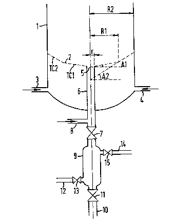
Flgures 1 and 2 show ln dlagram form:
. - ~
~822Z`7
12
- at (1) a fluidised bed apparatus comprl~lng in the vicinlty of
its base,
- at (2) a fluidisation grid consisting of the ~oined lateral
surface~ of two truncated cones of revolution TCl and TC2,
- at (3) and (4) the inlet pipe~ for fluldisation gas,
- at (5) the central aperture of the fluidisation grld
communicating,
- at (6) wlth a di~charge pipe which make~ it possible to
withdraw rapidly the granules or agglomerates which may be
deposited on the fluidisation grid (2) or present in it~
vicinity.
In Figures 1 ant 2:
- Al represents the angle formed by the generatrlx of the
truncstet cone of revolution TC1 with the horizontal plane,
this angle belng ln partlcular zero in Figure 2,
- A2 represents the angle formed by the generatrix of the
truncated cone of revolution TC2 wlth the horizontal plane,
- r represents the radius of the clrcle corresponding to both the
smaller base of the truncated cone of revolution TC1 and the
central aperture (5) of the fluidisation grid,
- R1 represents the radius of the clrcle correspondlng to the
larger base of TC1 and the smaller base of TC2, and
- R2 represents the ratius of the clrcle correspondlng both to
the larger base of TC2 and the horizontal cross-sectlon of the
fluidised bed apparatu~ (1).
The fluldlsed bed apparatus repre~ented ln Flgure 3 comprises a
fluidisation grid having a central aperture, two inlet pipe~ for
fluitisation gas ant a discharge pipe a~ shown diagramatically by
the various elements (1), (2), (3), (4), (5) and (6) in Pigures 1
and 2; it al~o comprises:
- at (7) a full-flow rapit-opening valve arranget on the
tischarge pipe (6),
- - at (8) a gas feet tube makin8 lt posslble to circulate in the
tischarge pipe (6) a rising 8as stream,
- at (9) a tischarge chamber provited in its lower part with an
12
~.~azxz7
13
outlet pipe (10) capable of being closed by a valve (11),
- at (12) piping provided with a valve (13) making it possible to
introduced optionally an inert gas into the discharge cha~ber
(9), and - st (14) piping provided with a valve (15) making it possible to
low~r rapidly the pressure prevailing in the di~charge chamber
(9) if necessary.
The fluidised bed apparatus represented in Figure 3 is employed
in the following manner, with a vlew to discharging the granules or
agglomerates deposited on a fluidisation grid or present in its
vicinity.
The solid ~ubstances in powder formed contained in the fluidised
bed apparatus (1) being maintained in the fluidised state by the
introduction of fluidisation gas into the pipes (3) and (4), g88 is
continuously introduced into the tube (8) it being possible for this
to be identical to or different from the fluidisation gas; the
rising speed of the gas in the discharge pipe (6) is comprised
between 5 and 50 times the minimum speed of fluidisation of the
solid substances in powder form in the discharge pipe (6);
preferably the risin8 speed of the gas in the discharge pipe (6) is
such that the solid substances in powder form liable to be present
in this pipe (6) are entrained upwards by what is known as the "plug
flow" effect; in a flow of the pulsating type, the heat exchanges
between 8as and solid are very intense, which makes possible an
effective cooling of the solid substances in powder form, which may
be too hot, and are liable to be present in the pipe.
In order to discharge the granules or agglomerates present on
the fluidisation grld (2) or situated in its vicinity, the
valve (17) is opened 80 as to place the discharge pipe (6) in
communication with the chamber (9) in which the pressure i8
appreciably lower than that prevalling in the fluitised bed
apparatu~ (l); the speed of opening of the valve (7) may be chosen
such that the gas current created from top to bottom in the
discharge pipe (6) is not interfered with by the gas current
introduced by the tube (8). Owing to the special form of the
13
~2E~227
14
fluidlsation grid (2), the granules or agglomerates depos1ted on it
are mostly as~embled in the central part of the said grid consisting
of the lateral ~urface of TCl; the granules or agglomerates
deposited on the part situated beyond the central part of the
fluidisation grid, that i8 to say consisting of the lateral surface
of TC2, slide by gravity along this grid into the central part.
The rapid opening of the valve (7) produces an effective a6piration
of all the particles present on the central part of the fluidisation
grid or located in its vicinity. The valve (7) is maintained open
for a short period of the order of a few seconds in order to permit
filling of the discharge chamber (9). After the closure of the
valve (7), the contents of the discharge chamber (9) are discharged
to the outside, by the opening of the valve (11). After the closure
of the valve (11) and the re-establishment of the desired pressure
in the discharge chamber (9), a new discharge operation may be
effected.
It may be expedient to equip the discharge chamber (9) w~th
piping (12) and (14) equipped with the valves (13) and (15)
respectively. As soon as the discharge chamber (9) has been filled
ant the valve (7) has closed, it may be preferable in certain cases
to open the valve (15) to lower the pressure prevailing in the
discharge chamber (9) rapidly, then, by opening the valve (13), and
introducing a gas, whlch may be inert, via the plplng (12) to
guarantee a clrculatlon of this gas through a dlscharge chamber (9)
during a period sufficent to eliminate, for example, the residuals
of the gaseous mixture coming from the fluidised bed apparatus (1).
The valves (13) and (15) are then closed before discharging the
contents of the discharge chamber (9) by opening the valve (11).
As it has been possible to note after several months of
industrial exploitation of a fluidised bed apparatus producing
polyethylene in the gas phase according to the invention, it is
possible to effect under excellent operating and safety conditions,
the rapid discharge outside the fluidised bed of the granules and
agglomerates deposited on the grid or present in its viclnity.
14
~282227
Example 1
A polymerisation of ethylene ln the gas phase is carrled out in
the fluidised bed device such as represented in Figure 3, comprising
a fluidised bed apparatus (1), serving as polymerisatlon reactor and
having the form of a cylinder revolution with a radius R2 - 1.5
metres and a vertical axis. The lower part of the fluidised bed
apparatus (1) comprises a fluidisation grid (2) which co;l unicates
at its centre via a circular aperture (5) with radius r - 0.05metres
with a discharge pipe (6) having the form of a cylinder of
revolution of radius r and a vertical axis. The discharge pipe (6)
is provlded with a full flow rapld opening valve (7) of the
spherlcal casing type, actuated by a pneumatlc control providing its
complete opening in approximately 0.5 second. It also comprises a
feed tube for gas mixture (8), which is permanently traversed by a
throughput of approximately 25 m3/h, this gaseous mixture having the
same composition and bein8 at the same pressure and temperature as
the gaseous mixture feeding the fluidised bed apparatus via the
pipes (3) and (4). The discharge pipe (6) is connected to the
discharge chamber (9) of volume V, equal to 1.100 cu metre. This
chamber is provited in its lower part wlth a dralnage pipe (10)
comprising a full flow valve (11) of the spherical ball casing type.
The pressure of 2.1 MPa existing in the fluidised bed apparatus (1)
is malntained constant during polymerisation; that existing in the
discharge chanber (9) is atmospheric pre~sure.
A gaseou~ mixture is circulated through the fluidised bed which
comprises 50% by volume of ethylene and 50% by volume of hydrogen,
at a temperature of 92C. This gaseous mixture circulates at the
rising speet of 50 cm/sec through the fluidised bed consisting of
particle~ of ethylene being polymerised, having a mean diameter by
mass of 650 microns. There is also introduced into the fluidised
bed apparatu~ (1) an olefin polymerisation catalyst used in the form
of a prepolymer, cataly~t and prepolymer being prepared according to
the information in Example 1 of French Patent No. 2405961.
The fluidisation grid (2) consists of the ~oined lateral
surfaces of two coaxial truncated cones of revolution TC1 and TC2,
~28Z2Z7
16
having a generatrix forming with the horizontal plane an angle Al of
6 and an angle A2 of 12 respectively. The radius Rl of the clrcle
constituting the co~mon base of the two truncated cones of
revolution TCl and TC2 is equal to 0.7 metres. The apertures of the
grid have the form of a cylinder of revolution of 3 mm diameter and
a vertical axis in relation to the plane of the grid. The ratio of
the atmission surface area to the total surface area of the grid is
equal to 1/34. These apertures are arranged regularly on the
fluidisation grid according to a network of the centred hexagon
type, each aperture being at the apex of an equilateral triangle
having a side of 22 mm.
In order to purge the lower part of the fluidised bed apparatus
(1), the following operations are performed without stopping
polymerisation:
15 - The valve (7) is opened and this valve is left open for about
10 secs, the valve (11) and the valves (13) and (15) remaining
closed, and the gas stream arriving via the tube (8) being
maintained at a constant throughput;
- The valve (7) is closed, then in order to avoid any risk of
continued polymerisation in the discharge chamber (9), the
valve (15) is opened in order rapidly to lower the pressure
existing in the discharge chamber (9), this pressure thus
decreasing from 2.1 MPa to approximately atmospheric pressure;
- Next, by openlng the valve (13), a current of nitrogen
introduced via the piping (12) is circulated for several
d nutes through the polyethylene powder contained in the
discharge chamber (9);
- Next the valves (13) ant (15) are closed and the contents of
the discharge chamber are collected by opening the valve (11);
when the discharge chamber (9) is empty the valve (11) is
closed.
After these operations it may be found, after stopping the
polrmerisation and degassing the fluidised bed apparatus, that no
agglomerate remains deposited on the fluidisation grid (2) or
present in the vicinity of same, and that the use of this
16
.. , -- .. , .. ~
17
fluidisation grid does not favour th~ form~tion of agglomerates in
the fluidised bed by any "channelling" phenomena.
Example 2
Polymerisation of ethylene is carried out by means of an
installation identical to that described in Example 1, except for
the fact that instead of using a fluidisation grid having an angle
Al of 6 and a radius Rl of 0.7 metre, a fluidisation grid ~9
used having an angle Al of 0~ and a radius Rl of 0.6 metre, this
grid being such as represented diagrammatically, in Flgure 2.
The operations described in Example 1 are performed and, after
stopping the polymerisation and degassing the fluidised bed
apparatus, it is found that no agglomerate remains deposited on the
fluidisation grid (2) or present ln its vicinity, and that the use
of this fluidisation grid does not favour the formation of
agglomerates in the fluidised bed.
~,. . . .