Note: Descriptions are shown in the official language in which they were submitted.
~;~8~439
.
BACKGROUND OF THE I~VENTION
In -the prior art, there are numerous machines for
collating or sorting paper sheets as they are supplied from a
source such as a printer or copier machine, wherein sheets are
either selectively or sequentially transported from a supply of
sheets to trays adapted to receive the sheets in collated or
sorted sets or order. In certain of such collating or sorting
machines, a sheet transport is provided to carry sheets to
receiver trays, wherein, in the sheet path, deflectors or fingers
are disposed to normally allow sheets to pass by a given tray,
10 but upon actuation to a sheet deflection position, to deflect the
sheet into a tray. An example of such a collator or sorter is
exemplified in my prior patent 3,937,459 granted February 10,
1976.
A travelling de~lector has also been employed to direct
15 sheets into successive trays from a path extending past the inlet
end of the trays, as exemplified in Snellman pa-tent 3,414,254
granted December 3~ 1968, and Raible et al patent ~1,006,89~
granted February 8, 1977, and Arvett et al patent 4,216,955
granted August 12, 1980.
Also it is known, as shown in Wentworth patent 2,328,317
to index a travelling transport past spaced trays to feed sheets
into the trays.
Such prior devices have typically employed complex
travelling belt systems to transport the sheets to the loca-tion
25 at which they are fed into the trays, either by deflection of the
sheet or by the beam strength of the sheet, as well as, in some
cases, the velocity of the sheet.
In the Raible et al and Arvitt et al devices the sheets
are positively driven into the trays by virtue of deflection of a
30 belt type transport towards the inlet to the tray from a straight
~2f~2~39
--2--
condition by a travelling device which causes the helt to form
feea path diverting the sheet into the tray.
SUMMARY OF THE IN~ENTION
The present invention combines and simplifies certain
features of the prior art in such a manner as to produce a novel
sheet transporting and diverting structure whereby the sheets can
~e driven into selected or sequential trays, so that the
apparatus can ~e rapidly operated to provide random access to the
trays, ~y use of novel deflector means providing selec-tive nip
points between opposing rollers which cause the sheet to be
turned approximately 90 by the confronting feed rolls at the
selected nip point into a tray from a straight path extending
past the trays.
A modular construction is provided, whereby a selected
number of drive roll and diverter units can be easily installed
in a housing of selected height. Each feed roll unit has drive
means adapted to cooperate with the drive means of another feed
roll unit upon assembly into the~housing.
BRIEF DESCRIPTION OF THE DRAWINGS
Fig. 1 is a side elevation of a sheet receiver in
accordance with invention, showing in broken lines two supply
devices;
Fig. 2 is a rear elevation of the sheet receiver, taken
on the line 2-2 of Fig. 1, and on an enlarged scale;
Fig. 3 is an enlarged vertical section on the line 3-3
o~ Fig. 2;
Fig. 4 is a fragmentary detail view, showing a divertor
moved to a position to direct a sheet into a selected bin;
Fig. 5 is an enlarged, fragmentar~v horizontal section on
the line 5-5 of Fig. 2, showing an actuator means to shift a
selected diverter to a sheet diverting position;
X8~39
Fig. 6 is a fragmentary vertical section on the line 6-6
of ~ig. 5, showing the paper feed drive;
Fig. 7 is an enlarged fragmentary, horizontal section on
the line 7-7 of Fig~ 2, showing the diverter retracting means;
and
Fig. 8 is a vertical, fragmentary section on the line
8-8 of Fig. 7.
DESC~IPTIO~ OF THE PREFER~D EMBODIMENT
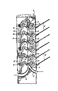
As seen in the drawings a sheet receiver appartus S is
dispos~d to receivs sheets o~ paper deli~ered from a source. For
illustrative purposes, alternate sources are shown in broken
lines in Fig. l. On the left of the receiver S a photocopying
machine or copisr C is shown having outlet feed roll means 10 for
directing sheets, as indicated by the arrows, to the receiver S.
At the right of the receiver another source of sheets is shown in
broken line and is referred to herein as a printer P having
outlet feed roll means ll.
Receiver S has a plurality of sheet receiving trays 12
into which sheets are to be directed by sheet diverted means D,
as the sheets are supplied to the receiver S and moved through a
transport system T which includes the diverter means.
Referring to Figs. 2 and 3, the transport means T
comprises a set of horizontally extended and vertically spaced
drive roll assemblies 12, the peripheries of which are on a
common vertical plane. The drive rolls 13 are opposed by a
number of vertically and horizontally spaced nip rolls 14, all
except the uppermost of which normally have the outer peripheries
~ertically aligned on the same ver-tical plane as the drive rolls
13, so as to oppose the latter and apply pressure to a sheet of
paper as it is being moved between the drive rolls and the nip
~213Z~39
--4--
rolls. The nip rolls 14 are in~orporated in the di~erter means
D. ~ach diverter means D, except for the uppermost one of them,
includes a number of horizontally spaced lever arms 15
respectively mounted upon a horlzontally extended rock shaft 16,
which, as will be later described, is adapted to be angularly
moved to effect diversion of the sheets into selected or
respective trays 12. ~-t the outer end of each lever 16 is a
pivoted arm 17 in which the nip rolls 14 are rotably supported.
Suitable springs, such as leaf springs 18 which are disposed, in
the illustrative embodiment, between the rock shafts 16 and the
nip roll supporting shafts 19 to normally bias pivot arms 17
towards the drive rolls 13, while, as will be later described,
enabling the rock shafts 16 to be actuated in a clockwise
direction as viewed in Fig. 3 to effect a change in the angular
relation of the axes of -the nip rolls and the drive rolls, from
the normal horizontal alignment as shown in Fig. 3, thereby
changing the nip point.
As seen in Fig. 3, the receiver apparatus has an inlet
guide structure 20 adapted to receive successive sheets supplied
rom copier C and to direct the sheets in an upward direction to
be engaged between the lowermost drive roll and nip roll. In the
alternative, the structure is such that a second guide structure
21 is provided to receive sheets from the printer P to direct the
sheets upwardly to the lowermost nip and feed rolls. Sheets
engaged bet~een the lowermost nip and feed rolls are transported
in a straight path vertically past all of the trays 12, except
the uppermost of the trays, when the diverters ~, except for
the uppermost diverter, are in the normal positions of Fig. 3.
At the uppermost feed rolls 13 the uppermost diverter is mounted
3~ upon a stationary shaft 22, so that the uppermost nip roll is
--5--
always biased towaras the uppermost feed roll to cause the travel
of the sheet to be altered from the straight vertical path to a
horizontal path, whereby the sheet is deflected into the ~:
uppermost tray. As a resuIt, if the receiver apparatus is being
employed in association with the copier C and the receiver is
being operated in a non-sort mode, then each successive sheet
will be carried from the inlet guide 20 to the uppermost tray 12,
ana all sheets will be stacked in the latter~
In the sorting mode of operation, assuming that the
sorting operation is in a downward direction from the uppermost
tray to the lowermost tray, the deflectors are su~uentially
actuated, as will be later described~ so that the diverters are
roc~ed in the clockwise direction to move the nip rol1 14 of the
second rom the upper di~erter downwardly, as seen in Fig. ~,
into confronting drive relation with the second from the
uppermost drive roll 13, whereupon, the next sheet to move
upwardly through the transport will be diverted from the vertical
path to substantially a horizontal path and be driven into the
second from the uppermost tray. The same sequence of events will
cause the following sheets to be se~uentially fed into the
successive lower trays as successively lower diverters are
actuated.
In the alternative, in the case that the shee-ts are
being fed from the printer P to the inlet guide 21, the sheets
will also be fed upwardly in the straight path between the
successive drive and nip rolls, but, as will be later described,
the rock shafts 16, under these conditions, may be actuated
selectively and/or randomly, whereby the sheets may be fed into
any selected tray 12. By the same token, it will be observed
that sheets entering the guide 21 with printed matter on the
~2~3Z439
--6
upper surface will be inverted as ~hey exit the respective
diverters so as to enter the trays face down, as is preferred in
the case of printers capable of feeding printed matter face up
commencing with the first and concluding with ~he last of a set
of prin-ted pages.
Referring to Figs. 5 and 7, it will be seen tha~ in the
preferred form the drive rolls 13 are mounted upon tranversely
extended shafts 23, and preferably consist of resilient material
to enhance frictional engagement of a sheet between the drive
rolls and the nip rolls. Also installed upon shaft 23 between
the drive rolls is a number of cylindrical members 24 which are
proveded to substantially bridge the space between the drive
rolls, thereby confining the sheets to a vertical path and
inhibiting flexure of the sheets between the drive rolls. The
drive rolls 13 and the cylindrical members 24 are shown as
separate elements on the shaft 23, but it will be apparent that
these elements may be molded of the same material upon the shaft
23. In the form shown in Fig. 5, the right hand end of each
shaft 23 extends through a mounting block 25 formed with flanges
26 which are adapted to extend into companion elongated grooves
which may be provided in a convenient form in a vertically
extended extruded housing 27. As best seen in Fig. 6, each block
25 accommodates the shaft 23 and also supports a shaft 28 on
which is rotably supported an idler 29 in mesh with the drive
gear 30 on the shaft 23. Accordingly, any suitable number of the
assemblies of shafts and blocks 25 can be utilized in the housing
extrusion of a selected height, and, on assembly, the adler and
drive gears are meshed.
Correspondingly, at the left of the receiver, as shown
in Fig. 7, the shafts 23 are rotably supported in an end block 31
~Z~243g
-7-
having ~langes 32 adapted to be receive~ in verticall~ extended
grooves in a housing ex-trusion 33, where~y, the structure is
truly modular.
Means are provided for rocking the respective rock
shafts 16 in opposite directions to the respective positions
illustrated by the second and third from the uppermost de1ectors
D shown in ~ig. 4. As seen in Fig. 5, the right hand end of the
rock shaft is supported in a support block 34 having flanges 35
adapted for engagement in companion slots in a vertically
exten~ed e~trusion 36. Within the extrusion 36 the shaft 16 has
a crank arm 37 engaged by a solenoid 38 adapted to,be energized
to move the roc~ shaft from a normal position of a deflecter D to
the position at which it is operative to divert a sheet into a
tray. It will be understood without repetitive illustration that
each rock shaft 16 is provided with a solenoid 38. At the other
side o~ the receiver, as seen in Fig. 7 each rock shaft extends
through another support block 39 having flanges 40 for engagement
in companion grooves in another e~trusion 41, a-t the left end of
the respective rock shafts. In addition, within the extrusion
41, each rock shaft 41 has a disc structure 42 fixed thereon and
having a pin 43. An elongated actuator member 44 having notches
45, extends vertically through each disc structure 42 and a pin
43 of each disc structure is disposed in the notch 45. At its
upper end the actuator member 44 is connected with a solenoid 46,
whereby retraction of the solenoid armature will cause the
actuator member to engage the respective pins 43 of each rock
shaft which has been actuated in the direction -to deflect a sheet
from normal position, as described above. This actuator
structure further enables the receiver to place sheets randomly
in selected trays, in the operating sequence which involves
12~32439
--8--
actuation of a selected rock shaft or any subsequent upper rock
shaft and thereafter operating solenoid 46 to retract the
deflectors to allow the transport of a sheet to the tray above.
It will be noted in connection with the above described
operation of the rock shafts, that when a diverter is shifted
from the normal position opposed to one feed roll 13 to a
position to effect engagement of the nip roll 14 with the next
feed roll below, the springs 18 maintain continuing pressure
engagement of the nip roll with the feed roll, so that the nip
roll travels downwardly about the periphery of the upper feed
roll until it is also in engagement with the lower feed roll. At
this point the force of springs 18 tends to normally hold the nip
roll between the adjacent feed rolls.
From the foregoing, it will be recognized t~at the sheet
feeding and diverting structure of the present invention is very
simple in that, among other things, the use of endless belts and
travelling nip points are eliminated, but the sheet is at all
times positively engaged between the feed and nip rolls,
virtually until the sheet is deposited in the tray. No provision
20 must be made for extension of belts, deflection of belts, or
other means for maintainin~ frictional drive between sheet feed
members is required~ The structure is well suited to se~uential,
top to bo~tom or bottom to top actuation of the diverters, as in
the case of typical sorting or collating of sets and sheets. In
addition, the structure is also well suited to the random
actuation of the diverters, so that the apparatus functions as a
pigeon holing receiver in wh.ich a desired number of sheets can be
directed to selected trays.