Note: Descriptions are shown in the official language in which they were submitted.
;7~
BACKHOE CREEP LEVER MECH~NISM
FOR AN EXCAVATI~G VEHICLE
BACKGROUND OF THE IMVENTION
1. Field of the Invention.
05 The present invention relates generally to
drive mechanisms for vehicles having attachments on
their back end. In particular, the pr2sent invention
is a creep lever mechanism for driving an Pxcavating
vehicle having a backhoe mounted to the back end,
while the operator seat is rotated toward the back of
the vehicle to per~it control of the backhoe.
2. Description of the Prior Art.
Excavating vehicles of the type having a
front end loader on their forward end and an
attach~ent such as a backhoe mounted to the rearward
end are well known and in widespread use. ~he
operator compartment in these vehicles typically
includes a sea$ which can be rotated from a drive/
loader control position facing the front of the
vehicle, and a backhoe control position facing the
back of the vehicle. Various vehicle drive control
mechanisms such as a steering wheel, ~oot pedal,
throttle, clutch, and gear shift lever are mounted in
the front of the operator compartment, as is the
loader control levers. Backhoe control levers are
located at the rear of the operator compartment. The
operator drives the vehicle and/or actuates the ront
end loader when the seat is in the drive/loader
control position facing the front of the vehicle~
When it is desired to operate the backhoe, the
vehicle is stopped and the seat rotated to the rear
60 the operator can access the bacXhoe control
levers.
-- 2
Many excavating vehicles of the type
described above have a torque converter drive which
includes a throttle, clutch, and shift lever. Still
other excavating vehicles have a hydrostatic drive.
05 Hydrostatic drives include a hydraulic drive pump
which controllably supplies fluid to a hydraulic
motor. The hydraulic motor is then coupled to the
vehicle's wheels through a drive train. When the
operator rotates the foot pedal in a ~ounterclockwise
manner, the hydraulic drive pump is stroked in a
first direction causing the vehicle to he driven
forward. To drive the vehicle in reverse, the
operator rotates the foot pedal in a clockwise manner
to stroke the hydraulic drive pump in the opposite
direction. Vehicle speed in both the forward and
reverse directions is determined by the extent of
rotation of the foot pedal.
It is often desired to reposition or move
the vehicle short distances while operating the
backhoe. However, when operating the backhoe, the
operator seat will be facing the back of the
vehicle. This being the case, the operator does not
have access to mechanisms used to drive the vehicle.
In vehicies that have a torque converter drive, the
operator will sometimes use the backhoe itself to
push the machine around. However, operation in this
manner is less than desirable. Furthermore, this
technique will not work on machinef~ having a
hydrostatic drive.
It is evident that there is a continuing
need for improved drive control mechanisms in
excavating vehicles. Specifically, a mechanism is
needed whif~h will permit an operator to drive the
vehicle while facing and con~rolling an attachm~nt
mounted to the back of the vehicle. The mechanism
should of course be relatively uncomplicated. The
mechanism should not interfere with the vehicle's
05 primary drive mechanisms either.
SVMMARY OF THE INVEN'rIO~
The present invention is a vehicle which
includes an engine and drive m0ans for driving the
vehicle with respect to ground. An operator
controlled work device is mounted to the back of the
vehicle. An operator compartment includes an
opexator seat movable between a vehicle drive
position and a work device control position. Vehicle
drive control means ~or controlling the drive means
are mounted within the operator compartment at a
location accessible to an operator when the operator
seat is in it~ drive position, and inaccessible to
the operator when the seat is in its work device
control position. Work device control means for
controlling the worX device are mounted within the
operator compartment at a location accessible to an
operator when the operator seat is in the work device
control position. Creep mechanism means mounted
within the operator compartment at a location
accessible to an operator when the operator seat is
in its work device control position are coupled to
the drive means. The operator can thereby control
the drive means and make the vehicle creep or move by
actuating the creep mechanism means.
In a preferred embodiment, the drive means
comprises a hydrostatic drive which includes a
hydraulic pump. The drive control means includes a
foot pedal mounted in the operator compartment in
front of the operator seat when the operator seat is
in the drive position, and a drive linkage coupling
the foot pedal to the hydraulic pump. The creep
mechanism means includes a creep lever, and creep
05 linkage means coupling the creep lever to the
hydraulic pump.
In still other embodiments, the creep lever
is releasably coupled to the hydraulic pump through
the foot pedal. A bell crank is movably mounted
adjacent the creep lever and coupled to the foot
pedal by a linkage. The creep lever is normally
biased to a position disengaged from the bell crank~
The creep lever will therefore not interfere with
motion of the foot pedal. If it is desired to move
the excavating vehicle while operating the backhoe,
the operator engages the creep lever with the bell
crank, and actuates the lever to move the vehicle
with respect to ground. The housing surrounding the
creep lever limits the range of motion of the creep
lever, and therefore the speed at which the vehicle
can be driven through its actuation. The creep
mechanism means is a relatively uncomplicated
addition to the vehicle, yet greatly enhances its
functional capabilities while the backhoe is being
operated.
BRIEF DESCRIPTION OF THE DRAWINGS
Fiyure 1 is a side view of an excavating
vehicle on which a backhoe creep lever mechanism in
accordance with the pre~ent invention can be
implemented.
Figure 2 is a view of the interior of the
operator compartment shown in Figure 1, showing the
creep lever, and the operator seat facing the front
of the vehicle.
~f~
Figure 3 is a view of the interior of ths
operator compartment ~hown in Figuxe 1, showing the
creep lever, and the seat facing the rear of the
vehicle.
05 Figure 4 is a view of the vehicle drive
system with the backhoe creep lever mechanism, foct
pedal, and linkages shcwn from the side~
Figuxe 5 is a view o the vehicle drive
system with the backhoe creep lever mechanism, foot
pedal, and linkages shown ~rom the top.
Figure 6 is an exploded view of the creep
lever and bell cxank shown in Figure 4.
Figure 7 is a view illustrating the creep
lever in i~s engaged and disengaged positions with
respect to the bell crank.
DETAILED DESCRIPTION OF THE PREFERRED EMBODIMENTS
~ n excavating vehicle 10 which includes a
backhoe creep lever mechanism in accordance with the
present invention is illustrated generally in Figure
20 lo ~ackhoe creep lever mechanism 12, which is
illustrated in Figure 4 and de cribed in detail in
subfiequent portions o~ this specification, permits an
operator to m~ke vehicle 10 creep or slowly move
while operating backhoe 28. A complete understanding
25 of backhoe creep lever mechanism 12 will be
facilitated by the following general description of
excavating vehicle 10.
As shown in Figure 1, vehicle 10 includes an
articulated frame 11 which is supported for over-the-
ground travel by wheels 14. Frame 11 is formed 'Dy aforward frame section 16 and a rearward frame section
18 which are pivotally connected by pivot mschanism
20. Cab 22, which encloses an operator's compartment
--6--
1 24, is mounted to rearward frame section 18. Excavating
vehicle 10 also includes a front end loader 26 and a
backhoe 28.
Front end loader 26 is mounted to forward frame
section 16 and includes a lift arm assembly ~0 having a
first end pivotally mounted to upright supports 32.
Bucket 34 is pivota~ly mounted to a second end of lift
arm assembly 30. Hydraulic lift cylinders (not visible
in Figure 1) raise and lower lift arm assembly 30 with
respect to forward frame section 16 in a known manner.
Bucket 34 is rotated with respect to life arm assembly
30 by a hydraulic tilt cylinder (also not visible in
Figure 1).
Backhoe 20 is pivotally mounted to rearward
frame section 18 of vehicle 10 by means of a backhoe
mounting mechanism 36. One such backhoe mounting
mechanism is disclosed in the applicant's U.S. patent
number 4,735,547 which issued April 5, 1988. Backhoe
mounting mechanism 36 includes one or more hydraulic
cylinders (not visible) which rotate backhoe 28 between
the upper travel position illustrated in Figure 1, and a
lower work position. Stabilizer arms 37, one of which
is shown in its retracted position in Figure 1, can be
pivotally mounted to backhoe mounting mechanism 36 on
opposite sides of vehicle 10.
Backhoe 28 includes boom arm 38, dipper arm 40,
and bucket 42. Dipper arm 40 is driven with respect
to boom arm 38 by hydraulic cylinder 44. Bucket 42
is rotated with respect to dipper arm 40 by
'` '
~.2~ 7~
hydraulic cylinder 460 Boom arm 38 is driven with
respect to backhoe mounting mechanism 36 by hydraulic
cylinder 48. Other hydraulic cylinders (not shown)
swing backhoe 28 to the left and right with respect
05 to its mounting mechanism 36.
Operator compartment 24 is entered through
door 23 and is illustrated in greater detail in
Figures 2 and 3~ An operator seat 50 is pivotally
mounted to floor 52 near the center of operator
compartment 24, between front wall 55 and rear wall
78 of cab 22, by pivotal mount 51. Pivotal mount 51
permits seat 50 to be rotated between and locked into
a first or travel/loader control position facing
front wall 55, and a second or backhoe control
position facing rear wall 78. Seat 50 is illustrated
in its travel/loader control position in Figure 2,
and in its backhoe control position in Figure 3.
Steering wheel 54 is mounted to and extends
from front wall 55 of cab 22. Foot pedal 56 is
pivotally mounted to floor 52 below steering wheel
54, and adjacent front wall 55, Other operator
controls including front end loader control lever 58,
throttle 59, gauges 60, backhoe mounting mechanism
control lever 62, and backhoe creep lever 64 are
mounted to a console 66 which is located against
right wall 68 of cab 22~ As shown, front end loader
control lever 58 and throttle 59 are located toward
the front of operator compartment 24 near front wall
55, while backhoe mounting mechanism control lever 62
and backhoe creep lever 64 are located toward the
rear of the operator compartment, adjacent rear wall
78. Backhoe control levers 70 and 72~ as well as
stabilizer arm control levers 74 and 76 are mounted
.. ..
~ .
4i7~
to and extend from back wall 78 of cab 22.
When ~eat 50 is locked into its travel/-
loader control position illustrated in Figure 2,
steering wheel 54, foot pedal 56, front end loader
05 control lever 58, and throttle 59 are within reach of
and accessible to the operator. The operator can
therefore drive vehicle 10 and/or control front end
loader 26 when seat S0 is in its travel/loader
control position. As described below, vehicle 10 can
include a hydrostatic drive system. Engine speed is
controlled through actuation of throttle 59. Speed
and direction of travel of vehicle 10 are controlled
by the extent and direction of rotation of foot pedal
56. Steering is controlled by steering wheel 54.
Lift arm assembly 30 and bucket 34 of front end
loader 26 are controlled through actuation of front
end loader contrvl lever 58.
Backhoe 28 is operated with seat 50 locked
in its backhoe control position shown in Figure 3.
Backhoe mounting mechanism 36 (Figure 1) is
controlled through actuation of mounting mechanism
control lever 62. Stabili~er arm 37 is controlled
through actuation of stabili~er control lever 76~ A
stabilizer arm on the right side of vehicle 10 (not
visible) is similarly controlled through actuation of
lever 74. Backhoe 28 is swung from left to right,
and boom arm 38 raised and lowered, through actuation
of lever 70. Dipper arm 40 and bucket 42 are
controlled through actuation of lever 72. By
actuating backhoe creep lever 64, the operator can
also make vehicle 10 slowly move or creep in forward
and rearward directions when seat 50 is in its
backhoe control position.
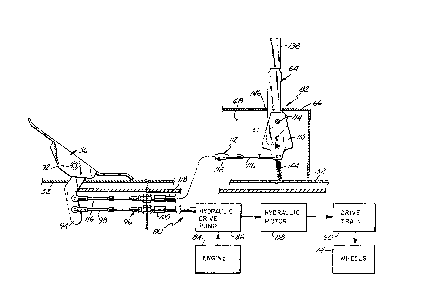
Hydrostatic drive syst~m 80, which includes
backhoe creep lever mechani~m 82 in accordance with
the present invention, is illustrated generally in
Figures 4 and 5. In addition to bachhoe creep drive
05 mechanism 82, hydrostatic drive ~ystem 80 includes
foot pedal 56, engine 84, hydxaulic drive pump 86,
hydraulic motor 88, drive train 90, and wheels 14.
With the exception of backhoe creep lever mechanism
82, hydrostatic drive systems such as 80 are well
known. Foot pedal 56 is pivotally mounted with
respect to cab floor 52 by means of pivot mechanism
92. A lever arm 94 which is mounted to the back of
foot pedal 56 e~tends below cab floor 52. Lever arm
94 is coupled to hydraulic drive pump 86 by means of
a drive linkage 96. Linkage 96 includes a linkage
cable 98 which has a first end connected to lever arm
94, and a second end connected to hydraulic drive
pump 86. Portions of cable 98 are shielded by
housing 100.
Engine 84 is mechanically coupled to and
rotates hydraulic drive pump 86. Using their foot,
the operator will rotate foot pedal 56 in a
counterclockwise manner to drive vehicle 10 in a
forward direction. This counterclockwise rotation of
foot pedal 56 forces linkage cable 98 toward
hydraulic drive pump 86 and strokes the pump in a
first direction. In respon~e, hydraulic drive pump
86 controls the flow of hydraulic fluid in a first
direction to hydraulic motor 88. Rotational motion
of hydraulic motor 88 is coupled to wheels 14 by
drive train 90, causing vehicle motion in a forward
dire~tion. Drive train 90 can include a gear box,
differential, and drive shafts, all of which are well
-- 10 --
known~ The amount of counterclockwise rotation of
foot pedal 56 controls the amount of hydraulic fluid
displaced by hydraulic drive pump 86, and therefore
the speed at which vehicle 10 is driven in the
05 forward direction. Clockwise ro~ation of foot pedal
56 controls the speed a~ which vehicle 10 is driven
in a rever~e direction in a similax manner. When not
actuated by the operator's foot, foot pedal 56 i~
returned to a neutral position by a bias mechanism
(not shown).
Backhoe creep lever mechanism 82 includes
creep lever 64, bell crank 110, and creep linkage
112. Creep lever 64 and b~ll crank 110 are pivotally
mounted with respect to cab side wall 68 about a
common rotational axis by pivot mechanism 114. Creep
linkage 112 includes a linkage cable 116 which has a
first end connected to lever arm ~4 of foot pedal 56,
and a second end connected to a lower portion 137 of
bell crank 110. Portions of cable 116 are enclosed
by housing 118.
Creep lever 64, bell crank 110, and pivot
mechanism 114 are shown in greater detail in Figure
6. Pivot mechanism 114 includes a bolt 120, washer
122, bushing 124, shaft 126, nut 128 and spherical
25 bearing 136. An aperture 132 extends through lever
64 between handle 138 and lower portion 137. The
axis about which creep lever 64 and bell crank 110
rotate is defined by the longitudinal axis of shaft
126. Shaft 126 extends through bushing 124, aperture
30 134 of bell crank 110 and inner race 136B of
spherical bearing 136. Outer race 136A of bearing
136 is fit within aperture 132 of lever 64. This
assembly is secured to cab side wall 68 by means
of bolt 120 which extends through bearing 136 and
shaft 126, and threaded into nut 128. A~ shown in
Figure 7, shoulder 127 of shaft 126 spaces lever 64
and bell crank 110 from side wall 68. Lever 64 is
05 spaced from bell crank 110 yet pivotally mounted with
respect thereto by bearing 136.
As perhaps best shown in Figur~s 6 and 7,
creep lever 64 includes a portion 137 which extends
downwardly from aperture 132 opposite handle 138.
Mounted to a lower end of portion 137 is a lug 140
which extends toward bell crank 110. Lug 140 is
sized and positioned to fit within aperture 142 of
bell crank 110. Spring 144 has a first end connected
to lug 140, and a second end connected to cab floor
52.
As a result of the cooperation be~ween inner
race 136B and outer race 136A of spherical bearing
136, creep lever 64 can be rotated in both parallel
and perpendicular directions with respect to the
longitudinal axis of shaft 126. When creep lever 64
is not actuated by the cperator9 spring 144 biases it
to a generally vertical position shown in ~olid lines
in Figure 7 at which lug 140 is withdrawn from
aperture 142 of bell crank 110. Creep lever 64 is
therefore disengaged from bell crank llOo Actuation
of oot pedal 56 by the operator when driving vehicle
10 with seat 50 in its travel/loader control position
will thereby be coupled to bell crank 110 by linkage
112, but will not cause any movement of creep lever
64. Creep lever mechanism 82 will not, therefore,
interfere with usual action of foot pedal 56.
When operating backhoe 28 the operator will
sometimes find it necessary to adjust the position of
vehicle 12. Using backhoe creep lever mechanism 82,
.
- 12
an operator will grab handle 138 and pull lever 64
toward operator seat 50. Lug 140 will then enter
aperture 142, and engage bell crank 110 as
illustrated in phantom in Figure 7. Movement of
05 creep lever 64 is then transferred to hydraulic drive
pump 86 through creep linkage 112, lever arm 94, and
drive linkage 96. Motion of creep lever 64 toward
the front of vehicle 10 will thereby cause the
vehicle to move or creep in a forward direction.
Similarly, motion of creep lever 64 toward the rear
of vehicle 10 will cause the vehicle to move or creep
in a reverse direction. The extent of movement of
creep lever 64, and therefore the speed at which
vehicle 10 can be driven in its forward and rearward
directions using creep lever 64, can be restrained by
the length of aperture 146 through which the creep
lever e~tends from console 66, or by other devices
such as bolts.
Although the present invention has been
described with reference to preferred embodiments,
workers skilled in the art will recognize that
changes may be made in form and detail without
departing ~rom the spirit and scope of the invention~
,. . ~ .