Language selection

Search

Patent 1282747 Summary

Third-party information liability

Some of the information on this Web page has been provided by external sources. The Government of Canada is not responsible for the accuracy, reliability or currency of the information supplied by external sources. Users wishing to rely upon this information should consult directly with the source of the information. Content provided by external sources is not subject to official languages, privacy and accessibility requirements.

Claims and Abstract availability

Any discrepancies in the text and image of the Claims and Abstract are due to differing posting times. Text of the Claims and Abstract are posted:

  • At the time the application is open to public inspection;
  • At the time of issue of the patent (grant).
(12) Patent: (11) CA 1282747
(21) Application Number: 1282747
(54) English Title: FLUID DISPENSING APPARATUS
(54) French Title: APPAREIL DEBITEUR DE FLUIDE
Status: Expired and beyond the Period of Reversal
Bibliographic Data
(51) International Patent Classification (IPC):
  • B67D 7/72 (2010.01)
  • B5B 9/08 (2006.01)
  • B67D 7/02 (2010.01)
(72) Inventors :
  • KOHLER, TILMANN L. (United Kingdom)
(73) Owners :
  • TILMANN L. KOHLER
(71) Applicants :
(74) Agent: GOWLING WLG (CANADA) LLP
(74) Associate agent:
(45) Issued: 1991-04-09
(22) Filed Date: 1986-10-10
Availability of licence: N/A
Dedicated to the Public: N/A
(25) Language of filing: English

Patent Cooperation Treaty (PCT): No

(30) Application Priority Data:
Application No. Country/Territory Date
85 25277 (United Kingdom) 1985-10-14

Abstracts

English Abstract


2619
ABSTRACT
FLUID DISPENSING APPARATUS
The fluid dispensing apparatus includes a
body portion 2 supporting a pump assembly 4 and a
valve assembly 6.
A fastening ring 12 has an internal screw-
thread for screw-threadedly engaging the neck 11 of a
container 13. A fastening ring retaining member 10
allows the ring 12 to rotate freely with respect to
the body portion but also has a central opening for
accommodating a fastening member 8 which acts both to
lock the member 10 to the body portion 2 and to
couple with an outlet duct 52 in the body portion
leading to the valve assembly 6.
In addition the member 10 defines a
separate passage which provides communication between
the pump assembly 4 and the interior of the
container 13.
The fastening member has a central opening
for receiving a pipe 14. which is arranged to extend
to the bottom of the container.


Claims

Note: Claims are shown in the official language in which they were submitted.

2619US
- 9 -
The embodiments of the invention in which
an exclusive right or privilege is claimed are
defined as follows:
1. Apparatus for dispensing liquids from a
container through an opening defined by the
container, the apparratus comprising:
a body portion,
a pump assembly for pumping air, supported
on the body portion,
a valve portion having an outlet duct
supported on the body portion,
a valve housed in said valve portion for
opening and closing the duct,
a locking member for locking the body
portion on to the opening of said container,
a locking member retainer rotatably
supporting the locking member,
a fastening member defining a liquid
flow passage, the fastening member being arranged to
be fastened to the body portion, to sealingly couple
the liquid flow passage to the outlet duct and to
lock the locking member retainer to the body portion,
the fastening member and the locking member retainer
when locked to the body portion defining an
uninterrupted fluid passage from the pump assembly
which does not directly communicate with the liquid
flow passage, and
sealing means located on the locking
member retainer for enabling a seal to be effected
between the container and the locking member
retainer when the locking member retained by the
locking member retainer is locked to the container.
2. Apparatus according to Claim 1 wherein the
body portion defines a cylindrical chamber
communicating with the duct and wherein said

2619US
- 10 -
fastening member is cylindrical and screw-threadedly
engages the said cylindrical chamber of the body
portion.
3. Apparatus according to Claim 2 wherein the
fastening member includes an annular seal providing a
seal between the fastening member and the chamber.
4. Apparatus according to Claim 1 wherein said
body portion defines a first cylindrical chamber
communicating with the duct and a second annular
chamber communicating with the pump assembly and
being coaxial with the first chamber, said locking
member retainer supporting an annular seal to effect
a seal between the outer wall of the second annular
chamber and the retainer, the uninterrupted fluid
passage being located within the boundary defined by
said annular seal.
5. Apparatus according to Claim 4 wherein the
first and second chambers are braced by bracing
ribs.
6. Apparatus according to Claim 1 wherein said
pump assembly comprises a piston and cylinder
assembly for pumping air into said uninterrupted
passage.
7. Apparatus according to claim 5 including a
non-return valve for allowing air flow through said
uninterrupted passage in one direction only.
8. Apparatus according to Claim 1 wherein the
neck of said container includes an external
screwthread and wherein said locking member is ring-
shaped and includes an internal screw-thread for
screw-threadedly engaging the external screw-thread
on the neck of a container, to lock the apparatus to
the container.
9. Apparatus according to Claim 8 wherein the
valve for opening and closing the duct includes a

2619US
- 11 -
valve member urged into a valve seat in said duct by
biassing means to act against the pressure of fluid
in said duct.
10. Apparatus according to Claim 9 including
lever means operable to open said valve against the
force of said biassing means.
11. Fluid dispensing apparatus for coupling to
a container housing a screw threaded neck said
apparatus comprising;
a pump assembly,
a valve assembly,
a body portion supporting the pump assembly
and the valve assembly,
a closure member having an internal screw-
thread for screw-threadedly engaging the screw-
threaded neck of said container,
a retaining member for retaining the
closure member on the body portion but which allows
the closure member to rotate relative to the
body portion, the retaining member defining a central
opening and
fastening member accommodated in the
central opening, the fastening member acting both to
lock the member to the body portion and to couple
with a duct in the body portion leading to the valve
assembly, the retaining member also defining a
separate passage which provided communication from
the pump assembly to the container when the apparatus
is secured thereto by the closure member.
12. Apparatus according to Claim 11 wherein the
fastening member defines a central aperture, and
a pipe accommodated in the aperture, and
extending to the bottom of the container when the
apparatus is coupled thereto, the fastening member
providing communication between the pipe and the
duct.

Description

Note: Descriptions are shown in the official language in which they were submitted.


747
2619
-1 -
~UID DISP~NSING APPARA~US
_
The pre~ent invantion relates to fluid
dispensing apparatus.
In previously proposed fluid dispensing
apparatus there is provided a pump unit for pumping
air into a sealed container to place the liquid in
the container under pressure. ~he unit has a
downwardly depending pipe which can be inserted
through a small orifice in the top of the container
to extend to the bottom of the container. The pipe
at its upper end, terminates in a valve which when
operated releases liquid forced up the pipe by the
pressure in the container, through an outlet spcut.
The downwardly depending pipe and another
pipe (for forcing air into the container) from the
unit pass into the container through a custom-made
rubber bung or seal which is tightly fitted into the
orifice. ~he pump unit is arranged to be clamped to
the rim of the container to prevent relative movement
between the pump unit and the bung so as to maintain
the seal in tact.
~ his unit is only suitable for containers
of a specific type.
It is an object of the invention to provide
an improved fluid dispensing apparatus for mounting
an externally screw-threaded opening of a container
in place of the normal screw-threaded closure cap o~
the container.
According to the present invention there is
provided apparatus for dispensing liquids comprising
a body portion supporting a pump assembly for pumping
air and a valve portion having an outlet duct housing
a valve for opening and closing the duct, a locking
member for locking on to an opening of a container, a
-35 locking member retainar rotatably supporting the
.

8~ 7 ~
2619
--2--
locking ~em~er, and a -fa~tening member defining a
liquid flow passage, the fastening member being
arranged to be fastened to the body member, to
sealingiy couple the liquid flow passage to the
outlet duct and to lock the locking member retainer
to the body portion, the fastening member and the
locking member retainer when locked to the body
portion defining an uninterrupted fluid passage from
the pump assembly which doe~ not directly communicate
with the liquid flow passage and sealing means
located on the locking member retainer for enabling a
seal to be effected between a container and the
locking member retainer when the locking member
retained by the locking member retainer is loc~ed to
the container.
According to the present invention there is
further provided fluid dispensing apparatus
comprising a body portion supporting a pump assembly
and a valve assembly, a closure member having an
internal screw-thread for screw-threadedly engaging a
screw-threaded nec~ of a container, a retaining
member for retaining the closure member on the body
portion but which allows the closure member to rotate
relative to the body portion, the retaining member
having a central opening accommodating a fastening
member which acts both to lock the member to the body
portion and to couple with a duct in the body portion
leading to the valve assembly, the retaining member
also defining a separate passage which provides
communication from the pump assembly to the container
when the apparatus is secured thereto by the closure
member.
~luid dispensing apparatus embodying the
: invention will now be described, by way of example,
~5 with reference to the accompanying diagrammatic
.

_3_ 2619
drawings, in which:
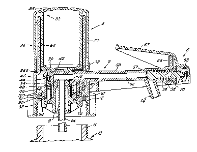
~ igure l is a section through the
apparatus;
~ igure 2 is a longitudinal section through
a locking ring retainer of the apparatus;
Figure 3 is a plan view of the retainer of
~igure 2;
~ igure 4 is a longitudinal section through
a fastening member of the apparatus of ~igure 1; and
~igure 5 is an underplan view of the
fastening member of Figure 4.
~ he fluid dispensing apparatus to be
described is arranged to dispense discrete quantities
of liquids from drums or containers t3.
Drums or containers for li~uid chemicals
are typically of plastics material and hold
quantities o~ liquid both smaller and greater than 20
litres. Access to such containers is through a
narrow cylindrical neck l1 upstanding from the roof
of the container 13. ~he neck 17 is externally
screw-threaded and is closed by an internally screw-
threaded cap (not shown). The apparatus to be
described is arranged to screw-threadedly engage with
the neck 11 and to seal the container 13 in place of
the cap.
The apparatus has a pump for forcing air
under pressure into the container and a duct through
which fluid can pass from the container to a manually
operable outlet valve.
As shown in ~igure l the apparatus
comprises a body portion 2 carrying a pump section 4
and a valve section 6. A boss or fastening member 8
is arranged to screw-threadedly engage the body
portion 2 to imprison a locking ring retainer 10 and
a locking ring 12 against the body portion 2. An

'74~7
2619
--4--
elongate pipe 14 is push ~itted into a central bore
or opening in the fastening member 8.
The pump section 4 has a cylinder defined
by a cylinder wall 0 upstanding from the body
portion 2. The cylinder is engaged by a piston
member 22 having concentric inner and outer spaced
walls 24 and 26. The cylinder wall 20 is arranged to
be accommodated in the annular space between the
inner and outer walls 24 and 26 of the piston member
22. The piston member 22 has a roo~ 28 which closes
the upper axiai ends of the two wallæ 24 and 26.
The lower axial end of the inner wall 24 o~
the piston member 22 is closed by a piston base 30
carrying a disk-like piston seal 32 which is arranged
to engage the inner face of the cylinder wall 20.
An interrupted annular flange 34 projects
outwardly from the outer surface of the cylinder wall
2Q adjacent the upper end thereo~; the interruptions
in the flange allow the passage of air therepast.
rrhe lower end 26a of the outer wall 26 is turned
inwardly. The arrangement is such that when the
piston member 22 is raised to perform its return
stroke the travel of the lower end 26a is arrested
when it engages the interrupted annular flange 34.
The annular flange is axially tapered,
increasing in diameter with distance from the top of
the cylinder wall, to enable the piston member 22 to
be readily coupled to the cylinder during assembly.
The body portion 2 below the cylinder
defines two coaxial walls, an inner wall 36 and an
outer wall 38. The annular space between the two
walls 36 and 38 is braced by a plurality of radially
extending bracing ribs (not shown). The space
between the outer wall 38 and the outer wall 40 of
the body portion is similarly braced by radially

~827~7
2619
--5--
ex~ending bracing ribs (not shown).
A through duct 42 in the body portion
provides fluid communication between the base of the
cylinder and the annular space between the two walls
36 and 38. A spring biassed non-return valve 44 is
accommodated in the duct 42. The valve 44 carries a
sealing ring 48 which is urged into engagement with a
tapering portion of the duct 42 by a spring 48.
The body portion 2 has an arm 50 which
couples the pump section 4 to the valve section 6.
The arm defines a channel 52 which extends from the
upper end of the chamber defined by the wall 36 to an
outlet spout 54.
A downstream valve 56 is located in the
channel 52 and is biassed by a spring 58 to close the
channel. ~he valve 56 carries an annular sealing
member 57 which is arranged to engage a valve seat
within the channel 52. The valve portion 6 carries a
pillar 66 which pivotally supports a lever 62. The
left hand end of the lever 62 defines an actuating
arm while the right hand end of the lever 62 is
coupled to the valve 56 by a head 68 which is in
screw-threaded engagement with the valve 56. A stop
70 which is screw-threadedly coupled to the arm
portion 6 provides an abutment surface for the
spring 58.
The fastening member 8 (also shown in
~igures 4 and 5) has a hollow body portion 72 with an
inner surface or bore defining a plurality of spaced
auxiliary e~tending ribs 74. ~he upper end of the
bore has a tapered section 79. When the pipe l~ is
forced into the bore it will be gripped by the ribs
74 and its upper end will make a seal with the
tapered section 79.
-35 At its upper end the body portion 72

~82747
261 9
--6--
defines a circw~ferential groove 76 for receiving a
ring seal 78. An intermediate section 80 of the body
portion 72 is screw-threaded for screw-threaded
engagement with a complementary screw-thread the
inner surface of the wall 36. When the fastening
member 8 is in screw-threaded engagement with the
body portion 2, the seal 78 ensures that a fluid
tight seal is effected between the channel 52 and the
pipe 14.
~he lower end of the body portion 72
carries a retaining flange 82. ~he retaining flange
82 is supported by a plurality of equiangularly
spaced bracing ribs 84.
The retaining flange 82 imprisons the
locking ring retainer lO and the locking ring 12 to
the body portion 2. The locking ring 12 i8 allowed
to rotate freely relative to the fastening member 8.
The locking ring retainer 10 (see also
~igures 2 and 3) comprises an annular member having a
central flange 90 arranged to abut the retaining ring
12 with its upper surface and engages an annular seal
92 on its under surface.
An annular wall 94 on the underside of the
flange 90 is arranged to accommodate the retaining
flange 82 of the fastening member lO.
A pair of concentric walls 96 and 98 on the
upper surface of the flange 90 define an annular
channel for receiving a ring seal 91 and the wall 38
depending downwardly ~rom the body portion 2. ~he
walls 96 and 98 are periodically interrupted to
accommodate the bracing ribs (not shown) bracing the
walls 36 and 38.
Mounted in the wall 96 is a hollow tube lO0
to matingly engage the duct 42 and so convey air from
the duct to the chamber defined by the wall 94 on the

~L2~3Z7~7
2619
--7--
underside of the flange 90. ~he flange 82 is
likewise provided with a plurality of equiangularly
spaced holes 102 to allow air to pa3s from the
chamber to the under~ide of the fastening member 8.
The locking ring 12 is internally screw-
threaded to screw-threadedly engage the neck portion
11 of the container 13.
The ring 12 has an inwardly extending
annular flange 120 which is arranged to engage the
flange 90 and cause the flange 90 to compress the
seal 92 against the upper rim of the neck 11 to seal
the apparatu~ to the container 13.
In operation with the apparatus sealed to
the container 1~, the piston member 22 is raised and
lowered ~everal times to pump air into the
container 13.
The forward stroke is performed by moving
the piston member 22 from the raised to the lowered
position and during this stroke the seal 32 engages
the ~ides of the cylinder and force~ the air below
through the duct 42. The seal 46 of the non-return
valve is moved away from the tapered portion of the
duct and the air passes through the tube 100 of the
locking ring retainer 10 and then through the
openings 102 of the fastening member 8 into the
container 13.
On the return stroke of the piston member
22, the seal 46 of the valve 44 close3 against the
tapered portion of the duct to prevent the e3cape of
. air.from the container and the piston seal is allowed
to move away from the side of the cylinder to admit a
fre~h intake of air. At the end of the return ~troke
the cylinder is again full of air and ready for the
next forward stroke. After reciprocating the piston
member 22 a number of times, sufficient pressure will

~Z8Z747
2619
--8--
be built up in the cylinder.
To dispense fluid from the c~linder 13 the
arm of the lever 62 ia pivoted to open the valve
member 56. The liquid under pressure in the
container 13 will be forced up the pipe 14 through
the channel 52 to paas the open valve 56 and
discharge through the outlet ~pout 54. Upon
releaaing the lever 62 the spring 58 will cloae the
valve 56 and the flow of liquid from the epout 54
will ceaae.
'

Representative Drawing
A single figure which represents the drawing illustrating the invention.
Administrative Status

2024-08-01:As part of the Next Generation Patents (NGP) transition, the Canadian Patents Database (CPD) now contains a more detailed Event History, which replicates the Event Log of our new back-office solution.

Please note that "Inactive:" events refers to events no longer in use in our new back-office solution.

For a clearer understanding of the status of the application/patent presented on this page, the site Disclaimer , as well as the definitions for Patent , Event History , Maintenance Fee  and Payment History  should be consulted.

Event History

Description Date
Inactive: IPC deactivated 2011-07-26
Inactive: IPC from MCD 2010-02-01
Inactive: First IPC derived 2010-02-01
Inactive: IPC from MCD 2010-02-01
Inactive: First IPC derived 2010-01-30
Inactive: IPC expired 2010-01-01
Inactive: IPC from MCD 2006-03-11
Inactive: Adhoc Request Documented 1995-04-09
Time Limit for Reversal Expired 1994-10-10
Letter Sent 1994-04-11
Grant by Issuance 1991-04-09

Abandonment History

There is no abandonment history.

Owners on Record

Note: Records showing the ownership history in alphabetical order.

Current Owners on Record
TILMANN L. KOHLER
Past Owners on Record
None
Past Owners that do not appear in the "Owners on Record" listing will appear in other documentation within the application.
Documents

To view selected files, please enter reCAPTCHA code :


To view images, click a link in the Document Description column (Temporarily unavailable). To download the documents, select one or more checkboxes in the first column and then click the "Download Selected in PDF format (Zip Archive)" or the "Download Selected as Single PDF" button.

List of published and non-published patent-specific documents on the CPD .

If you have any difficulty accessing content, you can call the Client Service Centre at 1-866-997-1936 or send them an e-mail at CIPO Client Service Centre.

({010=All Documents, 020=As Filed, 030=As Open to Public Inspection, 040=At Issuance, 050=Examination, 060=Incoming Correspondence, 070=Miscellaneous, 080=Outgoing Correspondence, 090=Payment})


Document
Description 
Date
(yyyy-mm-dd) 
Number of pages   Size of Image (KB) 
Drawings 1993-10-18 3 76
Claims 1993-10-18 3 108
Abstract 1993-10-18 1 21
Descriptions 1993-10-18 8 274
Representative drawing 2001-11-06 1 20
Fees 1993-03-25 1 30