Note: Descriptions are shown in the official language in which they were submitted.
PAr~NT
CMS No. 430~89-2010
7~3
FIELD OF TIIE INVENTION
This invention relates generally to devices for
heating and melting a piece of rod-shaped thermoplastic
material and discharging the melted material for use as an
adhesive. In particular, the present invention r~lates to a
manually operated device, commonly referred to as a "glue
gun", having a novel mechanism for advancing the rod-shaped
thermoplastic material.
BACKGROUND OF THE INVENTION
. . .
Glue guns for manual operation typically include a
tube shaped heating chamber and frequently a seal for the
entering glue stick at its rear end and a nozzle on its
front end for discharging the melted material. A housing is
generally inciuded which has a hand grip for the convenience
of the user. As the solidified glue stick is advanced into
the heating chamber, the portion of the glue stick which is
in the heating chamber is heated to beyond its melting
point, and the remainder of the still solid glue stick acts
as a piston to push the melted glue out the nozzle and onto
the work pieceO In early forms of glue guns, the glue stick
was advanced directly by the user, such as by pressing
directly on the back end of the glue stick with the user's
thumk .
Pressing directly on the glue stick has problems,
however, since the glue stick ha~ a tendency to become hot
during operation of the device. Furthermore, on occasion,
due to either failure by the user to allow sufficient time
for the heating chamber to warm up, or the user applying the
PA, r NT
CMS No. 430889-2010
79
glue at a rate too high to allow adeyuate melting of the
glue stick in the heating chamber, the glue may be
inadequately melted in the heating chamber. If the glue is
inadequately melted, and the user continues to attempt to
force glue through the heating chamber when it is still in a
solid or semi-solid state, excessive force may be imparted
to the parts of the mechanism and to the heating chamber,
causing damage.
Various types of advancing mechanisms which
advance the glue stick into the heating chamber without the
need for the user to directly press on the glue stick, and
which prevent excessive force, have been proposed. Prior
art glue stick advancing mechanisms include those having a
slidable carriage member holding the glue stick with an
angularly rotatable gripping member pivoted about a hinge
pin attached to the carriage member, such as described in
United States Patent No. 4,523,705, issued June 18, 1985.
As described therein, the gripper member is connected to a
tension spring which is, in turn, connected via a cable and
pulley arrangement to a sliding trigger. Squeezing the
trigger pulls the cable around the pulley which, in turn,
pulls on the tension spring which then pulls on the gripper
member to cause angular rotation of the gripper member about
the hinge pin. This forces a corner of the gripper member
against the glue stick, thereby clamping the glue stick in
the carriage member. Continued application of force to the
gripper member causes the carriage to slide longitudinally
forward with the glue stick to advance the glue stick into
the heating chamber. If excessive forces are applied, the
--2--
PATENT
CMS No. 430889-2010
7~3
spring expands, limiting the force which can be applied to
the gripper member.
While these prior art glue guns are Satisfactory
in many applications, the present design of the glue
advancing mechanism has difficulties. Attachment of the
gripper to the slidable carriage with a hinge pin increases
the cost of the mechanism if a metallic hinge pin is used
for strength. If the hinge pin is molded of plastic to
decrease cost, the strength of the hinge pin may not be
adequate. Use of a cable and pulley arrangement for
attachment to the tension spring, although satisfactory from
the standpoint of preventing excessive force, is
mechanically complicated and hence expensive.
OBJE~TS OF THE INVENTION
Accordingly, it is an object of the present
invention to provide a mechanism for advancing the glue
stick in a glue gun which is simple and inexpensive to
manufacture, and yet is robust and not prone to breakage.
It is a further object of the present invention to
provide a mechanism for advancing the glue stick in a glue
gun which has a simple pivoted hand lever connected directly
to a lever end of a gripper member by means of a tension
spring, with no other intermediate cables, llnkages, or
other parts.
SUMMARY OF THE INVENTION
The foregoing and other objects are achieved in a
device for heating a substantially solid heat softenable
PATENT
~MS No. 430889-2010
7~3
glue stick until said qlue is substantially melted and
ejecting the melted glue from the device. This device has a
housing and a heating chamber mounting in the housing. The
heating chamber has an opening therethrough, one end of the
opening defining an entrance for the substantially solid
glue stick and another end defining an exit for the melted
glue to be ejected. Means for advancing the substantially
solid heat glue stick into the entrance of the opening in
the heating chamber to melt the glue and to eject the melted
glue from the device are provided which includes a
longitudinally slidable carriage member with a longitudinal
opening for the glue stick. The carriage member has a
transverse opening in co~munication with its longitudinal
opening, and this transverse opening has internal peripheral
bearing surfaces. An angularly displaceable gripper member
which has a transverse lever and a gripper head is included.
The transverse lever has an end which extends through the
transverse opening, and the gripper head is receivable into
the transverse opening. The gripper head has a front end, a
rear end, an upper end and a gripper tooth near its front
and upper ends for gripping the glue stick. The gripper
head further has exterior peripheral bearing surfaces near
its front and rear ends which slidably bear against the
internal peripheral bearing surfaces of the transverse
opening to retain the gripper head in the transverse opening
while permitting angular displacemen~ of the head so that a
force applied to the end of the transverse lever will cause
PA~NT
~ 79 CMS No. 430889-2010
angular displacement of the gripper head to cause the
gripper tooth to grip the glue stick.
In another embodiment of ~he present invention, a
device for heating a substantially solid heat softenable
glue stick until the glue is substantially melted and
ejecting the melted glue from the device is provided. This
device has a housing and a heating chamber mounting in the
housing. The heating chamber has an opening therethrough,
one end of the opening defining an entrance for the
substantially solid glue stick and another end defining an
exit for the melted glue to be ejected. Means for advancing
the substantially solid heat glue stick into the entrance of
the opening in the heating chamber to melt the glue and to
eject the melted glue from the device are provided which
include a longitudinally slidable carriage member having a
longitudinal opening for the glue stick. The carriage
member has a first transverse opening in communication with
the longitudinal opening and a second transverse opening in
communication with the first transverse opening and also
transverse to the first transverse opening. The first
transverse opening has internal peripheral bearing surfaces.
A substantially T-shaped angularly displaceable gripper
member is included which has an upper member defining a
gripper head and a lower member defining a transverse lever.
The transverse lever has an end which extends through the
second transverse opening. The gripper head is receivable
into the first transverse opening and has a front end, a
rear end, an upper end and a gripper tooth near its front
PArENT
CMS No. 430889-2010
'79
and upper ends for gripping the glue stick. The gripper
head further has exterior peripheral bearing surfaces near
its front and xear ends which slidably bear against the
internal peripheral bearing surfaces of the first transverse
opening to retain the gripper head in the first transverse
opening while permitting angular displacement of the head.
Thus, a force applied to the end o~ the transverse lever
will cause angular displacement of the gripper head, causing
the gripper tooth to grip the glue stick.
In another embodiment of the present invention,
the first transverse opening of the carriage member extends
fully through one side of the carriage member so that that
gripper head can be received into the first transverse
opening from the side of the carriage member.
In still another embodiment of the present
invention, a device for heating a substantially solid heat
softenable glue stick until the glue is substantially melted
and ejecting the melted glue from the device is provided.
This device has a housing and a heating chamber mounting in
the housing. The heating chamber has an opening
therethrough, one end of the opening defining an entrance
for the substantially solid glue stick and another end
defining an exit for the melted glue to be ejected. Means
for advancing the substantially solid glue stick into the
entrance of the opening in the heating chamber to melt the
glue and to eject the melted glue from the device are
provided which include means consisting essentially of a
manually operable pivoted hand lever, a longitudinally
PATENT
~ 7~ CMS No. 430889-2010
slidable carriage member, an angularly displaceable gripper
membex retained in the carriage member and a tension spring.
The hand lever has a finger receiving end, a spring
attachment end and a pivot between these ends. The tension
spring has two ends, one of which is attached to the spring
attachment end of the trigger and the other of which is
attached directly to the gripper member to transmit force to
the gripper member to cause angular rotation of the gripper
member.
The foregoing and other objects, features and
advantages of the present invention will become apparent
from the following detailed description of illustrative
embodiments thereof, which is to be read in conjunction with
the accompanying drawings, wherein:
~RIEF DESCRIPTION OF THE DRAWINGS
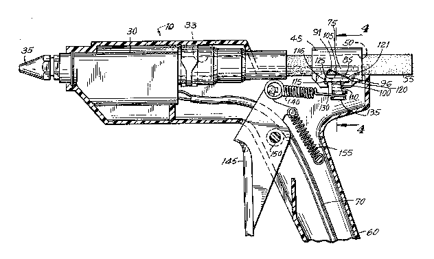
Fig. 1 is a perspective external view of a glue
gun utilizing an embodiment of the present invention and
showing an externally visible portion of the slidable
carriage.
Fig. 2 is a cross-sectional view taken along the
line 2-2.
Fig. 3 is a cross-sectional view taken along the
line 3-3 of Fig. 2.
Fig. 4 is a cross-sectional view taken along the
line 4-4.
FigO 5 is a cross-sectional view taken along the
line 3-3 showing the slidable carriage assembly in an
advanced condition with the gripper tooth of the gripper
PATENT
~ 7~ CMS No. 430889-2010
member gripping the glue stick when an excessive force is
not being appiied to the hand le~er.
Fig. 6 is a cross-sectional view taken along the
line 3-3 showing the slidable carriage assembly in an
advanced condition with the gripper tooth gripping the glue
stick when excessive force i5 being applied to the hand
lever.
DETAILED DESCRIPTIO~ -
Referxing now to the drawings in detail, and
initially to Figs. 1 and 2, a glue gun 10 constructed in
accordance with an embodiment of the present invention is
depicted. The glue gun 10 has a housing 15 constructed of
two medially split sides 20 and 21, preferably molded of
plastic. The housing 15 has a front portion 25 which houses
a heating chamber 30 (concealed in Fig. l but visible in
Fig. 2). At the front end of the gun is a nozzle 35
connected to the heating chamber 30 through which the glue
which is melted in the heating chamber 30 discharges or is
ejected onto the work piece. The heating chamber 30 has a
longitudinal opening 33 therethrough, the rear end of which
defines an entrance 31 for the substantially solid glue
stick, and the front end of which defines an exit 32 through
which the melted glue is ejected. A tubular seal 40,
preferably of rubberlike materialj is attached to the
entrance 31 of the heating chamber 30 to minimize leakaqe of
melted glue.
A longitudinally slidable carriaqe member 45 is
slidably mounted in the housing 15, behind the seal 40.
PAlENT
~ 3~ 7~ CMS N~. 430889-2010
This carriage 45 has a longitudinal opening 50 extending
through it, through which the glue stick 55 passes. The
upper rear portion 11 of the gun 10 is preferably open so
that the user can readily discern if glue is leaking past
the seal 40 at the entrance to the heating chamber 30, and
so that movement of the slidable carriage 45 can be
observed.
For convenient manual operation, the glue gun 10
is equipped with a hand grip 60 and an operating hand lever
65. Sq~eezing the hand grip end 65 of operating lever 145
causes the slidable carriage 45 to advance in a manner which
is depicted in Figs. 3-6, to be hereinafter described,
thereby advancing the glue stick into the heating chamber
30. An electric cord 70 is provided for delivering electric
current to the heating chamber 30.
Referring now to Figs. 3 and 4, the mechanism for
advancing the glue stic~ will be described in detail. The
carriage member 45 is preferably molded of a single piece of
a suitable material, such as plastic resistant to the
temperatures employed. The glue stick 55 extends through
the longitudinal hole 50 in the carriage 45, through the
seal 40, and hence into the entrance 31 of the longitudinal
opening 30 of the heating chamber 30. The hole 50 is
preferably sized somewhat larger than the outside diameter
of the glue stick to avoid jamming and to allow easy
insertion. The carriage 45 is preferably provided with
longitudinal rails 75 on each side which fit into
corresponding slots 80 on the housing 15. The carriage 45
has a transverse opening 85 in communication with the
PATENT
~ 3 CMS No. 430889-2010
longitudinal opening 50, which transverse opening preferably
extends fully through at least one side of the carriage to
allow easy assembly. In the preferred form of the invention
disclosed in the figures, the transverse opening 65 is
preferably wedge-shaped, with its narrow end 95 towards the
rear of the carriage and its wide front end 90 near the
front of the carriage. The internal surfaces of the wide
front end 90 and the narrow rear end 95 of the opening 85
define slidable internal peripheral bearing surfaces 91 and
96, respectively for the gripper member 100, to be described
in more detail below.
The gripper member 100, which is preferably
substantially T-shaped and preferably is molded of plastic
material, is received into the transverse opening 85. The
gripper member 100 has a head portion 105 and a lower
portion defining a transverse lever 110. The head 105 has a
front end 115 and a rear end 120. Front and rear ends 115
and 120 define peripheral slidable bearing surfaces 116 and
121, respectively, which slide against the internal
peripheral bearing surfaces 91 and 96 of the slot 85. A
wedge-shaped gripper tooth 125 having an acute angle is
included on the gripper head 105 near its front upper
portion, for gripping the glue stick.
The use of the carriage 45 with internal
peripheral bearing surfaces 91 and 96 bearing against the
peripheral front and rear bearing surfaces 116 and 121 of
the gripper head is believed to have considerabl~ advantages
over the hinge pin pivoted gripper members of the prior art.
--10--
PATENT
CMS No. 430889-2010
1~3~79
The gripper member of the present invention requires no
separate hinge pin, and is thus easy to manufacture.
Furthermore, because the major stresses are applied to a
relatively long surface of the rear bearing surface 96 on
the gripper head, decreased unit bearing stresses result as
compared to the concentrated stresses which are present when
2 hinge pin type gripper member is used.
The gripper head 105 is preferably slightly
smaller than the opening 85, and thus is freely insertable
from the side of the carriage member 45 to simply assembly.
Furthermore, the slot or opening 85 preferably extends
through at least one side of the carriage. This allows the
gripper 100 to be easily inserted directly from one side of
the carriage without disassembly of the carriage, thereby
simplifying assembly of the glue gun. The sides of the
housing 20 and 21 have internal faces 23 and 24 in close
proximity to the carriage and thus keep the gripper from
falling sideways out of the opening 50 during operation of
the device.
The carriage 45 preferably has a second
transverse, preferably downwardly open, slot 130 in
communication with the first transverse slot 85, through
which the transverse lever 110 extends. The transverse
lever 110 has a free end 135 to which is connected an end of
a tension spring 140. The other end of tension spring 140
is connected directly to an actuating lever 145 which is
pivoted by means of a hinge pin 150 in the housing. A
return spring 155 attached to the actuating hand lever 145
PAlENT
9 CMS No. 430889-2010
and the housing is included for applying a counterforce to
the actuating lever 145.
Referring now to Figures 5 and 6, a sequence of
operation of the advancing mechanism of the present
invention will now be described. Figs. 5 and 6 depict the
glue gun with the gripper member 100 angularly displaced so
that the gripper tooth 125 is engaged into the glue stick
with the carriage 45 in the advanced condition, as it would
be following depressing of the actuating lever 145. The
actuating lever 145 has been depressed by the user's fingers
to its maximum extent. In Figure 5, the heating conditions
in the heating chamber 30 are adequate for complete melting
of the glue stick, and no excessive force has been applied,
so the preloaded tension spring 140 is not been extended
beyond its initial preload.
An operating condition where insufficient melting
of the glue stick has occurred in the heating chamber is
depicted in Fig. 6. In this figure, actuating lever 145 has
been fully depressed, but insufficient melting is preventing
the glue stick from fully entering the heating chamber 30.
The movement of the spring 140 forward causes angular
displacement of gripper member 110 so that the gripper tooth
12~ engages the glue stick. But because the glue stick is
prevented from further advancement by the insufficient
melting, further movement of the actuating lever extends the
tension spring 140, thus preventing excessive forces from
being applied to the glue stick or the parts of the glue
gun.
-12-
PA'lENT
~ '7~3 CMS No. 430889-2010
It is thus seen that the present invention
provides an advancing mechanism for a glue gun which is
robust yet easy and inexpensive to manufacture and assemble.
The terms and expressions which have been employed
herein are used as terms of description and not of
limitation, and there is no intention in the use of such
terms or expressions of excluding any equivalents of the
features shown and described and portions thereof. In
particular, the term "glue" has been used for convenience to
refer to heat softenable substances, but this term is
intended to also include materials intended for sealing or
other uses other than adhesives. Similarly, the term "glue
stick" has been used to refer to the solidified rod-shaped
heat softenable material which is used in the glue gun, but
is not intended to be limited to only adhesives. Although
illustrative embodiments of the invention have been
described herein with reference to the accompanying
drawings, it is to be understood that various changes and
modifications can be effected therein without departing from
the scope or spirit of the invention.