Language selection

Search

Patent 1283541 Summary

Third-party information liability

Some of the information on this Web page has been provided by external sources. The Government of Canada is not responsible for the accuracy, reliability or currency of the information supplied by external sources. Users wishing to rely upon this information should consult directly with the source of the information. Content provided by external sources is not subject to official languages, privacy and accessibility requirements.

Claims and Abstract availability

Any discrepancies in the text and image of the Claims and Abstract are due to differing posting times. Text of the Claims and Abstract are posted:

  • At the time the application is open to public inspection;
  • At the time of issue of the patent (grant).
(12) Patent: (11) CA 1283541
(21) Application Number: 1283541
(54) English Title: TOY FIGURE HAVING MOVABLE BODY PARTS
(54) French Title: FIGURINES-JOUET A MEMBRES MOBILES
Status: Expired and beyond the Period of Reversal
Bibliographic Data
(51) International Patent Classification (IPC):
  • A63H 03/20 (2006.01)
  • A63H 03/16 (2006.01)
  • A63H 03/46 (2006.01)
(72) Inventors :
  • RYAA, JAN (Denmark)
  • POULSEN, OLE VESTERGAARD (Denmark)
(73) Owners :
  • INTERLEGO AG
(71) Applicants :
  • INTERLEGO AG (Switzerland)
(74) Agent: SMART & BIGGAR LP
(74) Associate agent:
(45) Issued: 1991-04-30
(22) Filed Date: 1986-12-03
Availability of licence: N/A
Dedicated to the Public: N/A
(25) Language of filing: English

Patent Cooperation Treaty (PCT): No

(30) Application Priority Data:
Application No. Country/Territory Date
5608/85 (Denmark) 1985-12-04

Abstracts

English Abstract


Abstract
In a toy figure with body parts movable in various
directions the body parts (in the embodiment shown the
legs) are connected with the body in a manner known per
se by means of a socket (13) designed to receive a ball
(6). To ensure long-term frictional stability between the
movable parts, the body part (9) is formed with a pair
of opposed walls (10, 11) designed to squeeze an engage-
ment face (7) which is contiguous with the ball (6).


Claims

Note: Claims are shown in the official language in which they were submitted.

22903-255
THE EMBODIMENTS OF THE INVENTION IN WHICH AN EXCLUSIVE
PROPERTY OR PRIVILEGE IS CLAIMED ARE DEFINED AS FOLLOWS:
1. A toy figure having movable body parts
including a joint between two mutually movably connected
body parts, said joint comprising a ball at an end of a
pin protruding from one body part and a depression
including a socket to receive said ball on the other body
part, wherein said pin further includes a rod spaced
apart from said ball and disposed between said one body
part and said ball, the outer surface of said rod
defining an engagement face, and said depression further
includes surfaces adapted to elastically engage said rod
engagement face when said ball is engaged in said socket.
2. A toy figure according to Claim 1,
characterized in that the engagement face for said
surfaces is a cylindrical thickened portion of the pin.
3. A toy figure according to Claim 1 or 2,
characterized in that said surfaces are defined by a pair
of opposed walls, the edges of said walls facing said one
body part being curved with the centers of curvature in
the vicinity of the socket.

22903-255
4. A toy figure according to Claim 1 or 2,
characterized by a semi-circular bead interposed between
the socket and the opposed walls opposite the pin portion
disposed between the ball and the rod.

Description

Note: Descriptions are shown in the official language in which they were submitted.


~33~
1 22903-255
A tov fiaure havina movab~le body parts
The invention concerns a toy figure having movable body parts,
where the joint between two mutually movably connected body parts
comprises a ball at the end of a pin protruding from one body
part, and where the other body part has a depression with a socket
to receive the pin so that the ball engages the socket.
A toy figure of this type is known e.g. rom the US Patent
Specification 1 868 049. This prior art, like later known
attempts at constructing movable joints on toy figures, is
vitiated by the drawback that the mobility appears to be "loose-
jointed". More particularly, there is no limit to the possible
movements so that the limbs may easily assume all possible
positions, and the ~riction, which might be intended for retaining
the body parts in a speclEic position with respect to the body,
disappears rapidly because oE wear. Therefore, the toy figure
rapidly becomes unab]e to serve its purpose, i.e. to stay in a
given position with some mutual friction between the movable
parts.
The object o-f the invention is to provide a toy figure of the
present type, which eliminates the above-mentioned drawbacks.
This object is achieved by providing a toy figure having movable
body parts including a joint between two mutually movably
connected body parts, said joint comprising a ball at an end of a
pin protruding from one body part and a depression including a
'~: ' , ,
. .

33~
la 22903-255
socket to receive said ball on the other body part, wherein said
pin further incLudes a rod spaced apart Erom sai.d bal.l and
disposed between said one body part and said ball, the outer
surface oE said rod deEining an engagement face, and said
depression further includes surEaces adapted to elastically engage
said rod engagement face when said ball is engaged in said socket.
Since the mentioned surfaces, preferably in the form of juxtaposed
surfaces of a pair oE opposed walls, serve as guide faces for the
motion of the body part and also elastically squeeze the said
engagement face so that a constant Eriction is maintained. This
results in a toy figure with a well-defined mobility of the body
parts, but also a languid mobility so that the toy figure can
remain in a E:ixed position, also after an extended period of time.
The technical. eEect described has especially relation to the hip
joint
.. , ~ ;

~;~E33~
structure, and the embodiment described below actually
relates to an embodiment of the hip ~joint structure.
Claim 2 defines preferred details in an embodiment where
the diameter oF the thickened portion is preferably larger
than the diameter of the ball~ providing for easier
assembly of the components.
The features defined in claim 3 enable the body part to
be moved close to the body itself. Claim 4 defines a
preferred way of keeping the ball in position in the
socket.
The invention will be explained more fully by the following
description of an embodiment wlth reference to the drawing,
in which
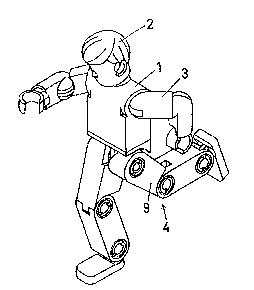
fig. 1 is a perspective view of an embodiment of the toy
figure of the invention,
fig. 2 shows the same as fig. 1, but with the left leg
removed 90 that the hip joint ball is visible,
fig. 3 is a perspective view of the inner side of a thigh,
fig. 4 shows the thigh of fig. 3, as viewed toward the
inner side, and
fig. 5 is a section through the embodiment of the hip
joint structure of the invention.
The toy figure shown in fig. 1 comprises a body 1, on which
a head 2, arms 3 and legs 4 are secured. These body parts
are rotatably secured on the body 1, and in the shown
3S embodiment the hip joint is constructed in accordance with
the invention. Fig. 2 shows that the hip structure com-
prises a pin 5 which protrudes from the body and has a
,- . '
'

~33~
ball 6 at the end. The pin 5 moreover comprises a
cylindrical portion 7 which serves as an engagement face
and has a larger diameter than the size of the ball 6,
and an area ~ oF reduced diameter is provided between the
engagernent face 7 and the ball 6.
Fig. 3 shows in perspective a thigh 9 which, according
to the invention, has a pair of protruding, opposed walls
10, 11 with a curved outer edge (see fig. 6). The opposite
end of the thigh in fig. 3 is formed with a knee link
structure 12, which will not be described in detail. Fig.
4 shows the thigh of fig. 3 from the inner side, and more-
over shows a hole 13 to receive the ball 6 and a semi-
circular bead 14 which will be explained more fully in
connection with fig. 5.
Fig. 5 is a section through the thigh 9 shown in figs.
3 and 4. The wall 11 and its curved outer edge are clearly
visible in fig. 5, which rnoreover shows in broken lines
the position of the hip joint ball from fig. 2. Thus, it
will be seen clearly how the hip joint ball is received
in the hole 13, and it will be understood how an additional
engagement for the movable parts has been provided in that
the inner side of the wall 11 (and the opposite side from
the wall 10) engages the cylindrical engagement face 7
with the predetermined elastic force, so that the leg can
assume suitably fixed positions with respect to the body.
Further, the bead 14 explained in connection with fig.
4 is clearly visible in fig. 5, said bead being disposed
opposite the portion of the pin 8 which has a reduced
diameter, so that the ball 6 cannot fall out of the hole
13. Thus, the leg can be pivoted forwardly and rearwardly
and can moreover be lifted to the side, said movement
being restricted by an inclined wall 15 which is also
visible in fig. 4.
- ~ :
. . ~ .

Representative Drawing
A single figure which represents the drawing illustrating the invention.
Administrative Status

2024-08-01:As part of the Next Generation Patents (NGP) transition, the Canadian Patents Database (CPD) now contains a more detailed Event History, which replicates the Event Log of our new back-office solution.

Please note that "Inactive:" events refers to events no longer in use in our new back-office solution.

For a clearer understanding of the status of the application/patent presented on this page, the site Disclaimer , as well as the definitions for Patent , Event History , Maintenance Fee  and Payment History  should be consulted.

Event History

Description Date
Inactive: Reversal of expired status 2012-12-05
Time Limit for Reversal Expired 2008-04-30
Letter Sent 2007-04-30
Inactive: IPC from MCD 2006-03-11
Inactive: Adhoc Request Documented 1998-04-30
Letter Sent 1997-04-30
Grant by Issuance 1991-04-30

Abandonment History

There is no abandonment history.

Fee History

Fee Type Anniversary Year Due Date Paid Date
MF (category 1, 7th anniv.) - standard 1998-04-30 1998-04-07
MF (category 1, 8th anniv.) - standard 1999-04-30 1999-04-12
MF (category 1, 9th anniv.) - standard 2000-05-01 2000-03-16
MF (category 1, 10th anniv.) - standard 2001-04-30 2001-03-16
MF (category 1, 11th anniv.) - standard 2002-04-30 2002-03-18
MF (category 1, 12th anniv.) - standard 2003-04-30 2003-03-17
MF (category 1, 13th anniv.) - standard 2004-04-30 2004-03-17
MF (category 1, 14th anniv.) - standard 2005-05-02 2005-03-07
MF (category 1, 15th anniv.) - standard 2006-05-01 2006-03-06
Owners on Record

Note: Records showing the ownership history in alphabetical order.

Current Owners on Record
INTERLEGO AG
Past Owners on Record
JAN RYAA
OLE VESTERGAARD POULSEN
Past Owners that do not appear in the "Owners on Record" listing will appear in other documentation within the application.
Documents

To view selected files, please enter reCAPTCHA code :


To view images, click a link in the Document Description column (Temporarily unavailable). To download the documents, select one or more checkboxes in the first column and then click the "Download Selected in PDF format (Zip Archive)" or the "Download Selected as Single PDF" button.

List of published and non-published patent-specific documents on the CPD .

If you have any difficulty accessing content, you can call the Client Service Centre at 1-866-997-1936 or send them an e-mail at CIPO Client Service Centre.

({010=All Documents, 020=As Filed, 030=As Open to Public Inspection, 040=At Issuance, 050=Examination, 060=Incoming Correspondence, 070=Miscellaneous, 080=Outgoing Correspondence, 090=Payment})


Document
Description 
Date
(yyyy-mm-dd) 
Number of pages   Size of Image (KB) 
Abstract 1993-10-19 1 10
Claims 1993-10-19 2 37
Drawings 1993-10-19 1 29
Descriptions 1993-10-19 4 119
Representative drawing 2000-07-18 1 9
Maintenance Fee Notice 2007-06-10 1 173
Fees 1997-04-15 1 46
Fees 1996-04-09 1 44
Fees 1995-04-10 1 39
Fees 1994-04-17 1 47
Fees 1993-04-12 1 26