Note: Descriptions are shown in the official language in which they were submitted.
i2B3652
A STATIC MIXING DEVICE FOR FLUIDS CONTAININ~ OR
CONSI9TING OF SOLID PARTICLES
This invention relates to a static mixing
device. More particularly, this invention relates to a
static mixing device for fluids containing or consisting
of solid particles.
Heretofore, various types of static mixing
devices have been known for the mixing of various types
of fluids. For example, Swiss Patents 662,5647 547,120 and
578,370 each describe a static mixing device which can
be used for the mixing of fluids. Howevèr, the static
mixing devices described in these patents all suffer
from a disadvantages of tending to become clogged when
dealing with fluids which contain or consist of solid
particles. Fluids of this kind can be in the form, for
example of various granulates which are required to be
uniformly mixed together, or liquids containing, for example,
fibers or other solid particles~ Generally, these fluids
may occur in public water treatment, for example, in the mixing
of chemicals into a sludge, in the paper making industry
and in the food industries, for example when pieces of
fruit are to be mixed into yogurt.
` "
, . . .
. -
~2~33~i~;2
Accordingly, it is an object of the invention
to provide a static mixing device which does not clog
when mixing fluids containing or consisting of solid
particles.
It is another object of the invention to provide
; a non-clogging static mixing device which ensures a homo-
geneous mixing at an acceptable pressure drop.
Briefly, the invention provides a static
mixing device comprised of a tubular casing which defines
a flow path and at least three webs disposed within and
tranversely across the casing. Each web is disposed in
transverely spaced crossing relation to a transversely
adjacent web while being lnclined to ~ longitudinal axis
of the casing. Xn accordance with the invention, the outer-
~5 most webs have an outer edge secured to the casing in
sealed relation and a terminal end spaced from the
casing to define a gap therewith. Each remaining inner
web has an outer edge secured to the casiny in sealed
relation and an opposite terminal end spaced from the
casing.
The construction of the webs is such that a
simple means i5 provided with prevents particles of solid
matter from being deposited or caught between the webs and
the wall of the tubular casing or between crossing webs.
Hence, satisfactory mixing can proceed in the device of a
fluid containing or consisting of solid particles.
--2--
. .
~z~3~ii~iæ
; The transversely disposed webs serve to form a
mixing element within the tubular casing. In addition, a
plurality of sets of webs may be disposed along the length
of the casing in order to define a plurality of mixing
elements. Further, the consecutively arranged mixing
elements may be disposed in offset relation to each other so
as to enhance the mixing capability of the static mixing
device.
In one embodiment, each mixing element may be
formed of three webs whereas in other embodiments, the
webs may be of a greater number, for example, five.
These and other objects and advantages of the
invention will become more apparent from the following
detailed description taken in conjunction with the drawings
wherein:
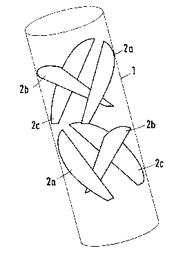
Fig. 1 illus~atesa perspective view of a
cylindrical tubular casing having two mixing elements
longitudinally dis~osed therein in accordance with the
invention;
- 20 Figs. 2a to 2d each illustrates a cross
sectional view through a mixing element having four
consecutively disposea mixing elements constructed in
accordance with the invention;
Fig. 3 illustrates a cross sectional view of a
modified mixing element employing five webs in accordance
with the invention; and
--3--
~ - ,
,.. ~. - .
S2
~83~
Fig. 4 illustrates a longitudinal s~ctional
view of the static mixing device of Fig. 3.
Referring to Fig. 1, the static mixing device
is formed of a cylindrical tubular casing 1 which defines
a flow path for a fluid having solid particles therein.
In addition, a pair of mixing elements are consecutiveIy
disposed in a 90 offset relation to each other longitudinally
within the casing 1. As indicated, each mixing element is
disposed in the casing for mixing a fluid passing therethrough.
Each mixing element is comprised of three webs
2a, 2b, 2c, with each web being disposed in transverely
spaced crossing relation to a transversely adjacent web while
being inclined to a longitudinal axis of the casing 1.
In this way, a gap remains between the webs at the crossing
points of the webs. In this respect, it may be convenient
to form groove-like recesses at the crossing places of the
webs in order to enlarge the gap.
Referring to Figs. 1 and 2a, the outermost webs
2 2a, 2c, have an outer edge which is secured to the casing 1
in sealed relation while a terminal end is space~ from the
casing to define a gap therewith. As indicated, the outer
edgesof the webs 2a, 2c are contoured to fit the cylindrical
wall of the tubular casing 1. The inner web 2b has an
outer edge at the top as viewed which is secured to the
casing 1 in sealed relation and a lower opposite terminal end
- which is spaced from the casing as more clearly fihown in Fig. 2a.
:. . . . .
i :
~8~
The webs 2a, 2b, 2c can be welded or soldered
to the tubular casing 1. Further, the casing 1 may be of
other cross sectional shape than of circular cross sectional
shape as viewed. For example, the casing mav have a
rectangular contour.
Referring to Fig. 2a, for improved flow behavior
sofar as satisfactory detachment at the web ends is concerned,
the web cross section~ may narrow towards the free ends.
Advantageously, the angle which the webs ma]ce
with the longitudinal axis of the casing1 is in the range of
from 30 to 60 and, more particularly, 30 and 45~.
As indicated in Figs. 2a and 2b, the webs 2a-2c
of the consecutively disposed mixing elements are disposed
in 90 offset relation to each other.
As indicated in Figs. 2a to 2d, where a mixing
device is provided with four mixing elements, the consecutively
disposed elements may each be turned 90 relative to each
; other.
Referring to ~ig. 3, a mixing element may be
composed of five webs 4a-4e. As indicated, the outermost
webs 4a, 4c each have an outer edge which is contoured to the
cylindrical tubular casing 3 while the remaining inner
webs 4b, 4d, 4e have an outer edge secured to the casing
in sealed relation while the opposite terminal end is
spaced from the casing wall.
`:
... . .. . . . .. . .
~2~33~2
As indicated in Fig. 4, the webs 4a, 4b, 4c
to one side of the caslng are dis~osed in parallel relation
while the remaining webs 4d, 4e are in parallel relation
to each other and in crossing relation to the webs 4a, 4b,4c.
Of note, it is theoretically possible for the
mixing device to have a number of webs in accordance with the
process for which the mixing device is to be used.
Mixing devices according to the invention have
been tested experimentally for various uses. For example,
colored and uncolored plastics granulate have been introduced
into a static mixer constructed in the above fashion through
a aller with a uniform color distribution being achieved
during mixing.
Other uses may reside, for example, in mixing
~5 flocculating agents in~o secondary clarified sludge before
a centrifugal decanter of a public sewage works for sludge
dewatering. The provision of a mixer according to the
invention meets the requirement for rapid and uniform mixing
in the manner necessary for effective use of chemicals.
Advantageously, the cross sections and the
longitudinal sectional shapes have flow-enhancing contours
and may, for example, be rectangular or elliptical or
semi-circular.
As indicated in Fig. 1, when in use, a flow of a
fluid containing or consisting of fluid particles can be
~a2836SX~
introduced into one end of the tubular casing 1, for example,
at the upper end. As the flow passes over and be~ween the
webs 2a, 2c of each mi*ing element, a mixing of the fluid
occurs. However, since the webs are spaced transversely
;~ 5 from each other as well as from the casing at the lower
ends, clogging of the mixing device is avoided.
The invention thus provides a static mixing
device which does not become clogged when dealing with
fluids which contain or consist of solid particles.
Further, the invention provides a non-clogging
static mixing device which ensures a homogenous mixing at
an accepable pressure drop.
As indicated in Fig. 1, the direction of flow
through the casing 1 is from to~ to bottom. In the
event that flow w~ld be rev~rsed, i.e. from bottom to
top, then the webs 2a, 2c would be reversed in a sense
that the lower ends would be secured to the casing while
the upper terminal ends would be spaced from the casing.
Likewise, for the embodiment illustrated in Fig. 4, the
flow is from left to right. For a flow in the reverse
direction, the orientation of the webs within the casing 3
would be reversed to accommodate the flow so that spaces
are not provided in which the particles in the fluid flow
may accumulate and clog.