Language selection

Search

Patent 1284265 Summary

Third-party information liability

Some of the information on this Web page has been provided by external sources. The Government of Canada is not responsible for the accuracy, reliability or currency of the information supplied by external sources. Users wishing to rely upon this information should consult directly with the source of the information. Content provided by external sources is not subject to official languages, privacy and accessibility requirements.

Claims and Abstract availability

Any discrepancies in the text and image of the Claims and Abstract are due to differing posting times. Text of the Claims and Abstract are posted:

  • At the time the application is open to public inspection;
  • At the time of issue of the patent (grant).
(12) Patent: (11) CA 1284265
(21) Application Number: 1284265
(54) English Title: JOINT CONNECTION
(54) French Title: RACCORD SUR JOINT
Status: Expired and beyond the Period of Reversal
Bibliographic Data
(51) International Patent Classification (IPC):
  • E04B 1/19 (2006.01)
(72) Inventors :
  • FRANTL, ERICH (Austria)
  • RAUNICHER, ALBERT P. (Austria)
  • HOFSTATTER, PETER (Austria)
  • FRANTL, WERNER (Austria)
  • ZEMLER, WILLIBALD (Austria)
(73) Owners :
  • "COMPROJECT" HANDELSVERTRETUNG UND TECHN. BURO FUR MASCHINENBAU FRANTL & CO. OHG
  • BEER, MANFRED
(71) Applicants :
(74) Agent: SMART & BIGGAR LP
(74) Associate agent:
(45) Issued: 1991-05-21
(22) Filed Date: 1987-01-13
Availability of licence: N/A
Dedicated to the Public: N/A
(25) Language of filing: English

Patent Cooperation Treaty (PCT): No

(30) Application Priority Data:
Application No. Country/Territory Date
A 68/86 (Austria) 1986-01-14

Abstracts

English Abstract


ABSTRACT
In a joint connection having a plurality of rods that
are combined to form a joint, the ends of the rods that protrude
through openings in a metal casing filled with hardenable filler
substance are necked down; in the necked down end section of each
rod there are two conical expander elements that can be tightened
against each other by means of a tension element, said expander
elements being under tension and situated on opposite sides of the
necked down portion of the rods.


Claims

Note: Claims are shown in the official language in which they were submitted.

21950-16
THE EMBODIMENTS OF THE INVENTION IN WHICH AN EXCLUSIVE
PROPERTY OR PRIVILEGE IS CLAIMED ARE DEFINED AS FOLLOWS:
1. A joint connection for frameworks having rigid joints,
comprising at least two rods that are combined to form a joint,
said rods being in the form of tubes that protrude through openings
in a metal casing that can be filled with a hardenable filler sub-
stance, and ending within the metal casing in necked down end
sections that form a positive lock, characterized in that within
the necked down end section of the rod there are two opposing coni-
cal expander elements on opposite sides of the necked down section
under tension, the expander elements having shapes that coincide
with the shape of the necked down section.
2. A joint connection as claimed in claim 1, characterized
in that the expander elements can be tightened towards each other
by means of a tension element that is arranged within the axis
of the tube and can be displaced longitudinally.
3. A joint connection as claimed in claim 1 or claim 2,
characterized in that the necked down section is formed by crimp-
ing the tube wall without any concomitant change in its cross
sectional area.

Description

Note: Descriptions are shown in the official language in which they were submitted.


~ ~ ~ 21950-16
The present invention relates to a joint connection for
rigid frameworks with rigid joints, having at least two rods that
are combined to form a joint, said rods being in the form of tubes
that protrude through openings in a metal casing that can be filled
with a hardenable filler substance and ending within the metal
casing in end sections that are necked down and form a positive
fit.
In joint connections of this kind, as have been disclosed,
for example, in GB-PS 271 709, the necked down end section in
each rod or tube constitutes a weakness. This makes it necessary
to over-dimension the rods in order that they can absorb the heavy
tensile forces and bending moments. Larger tensile forces that
act on the rods can deform the end sections, and the positive and
locking fit in the filler substance is lost. This problem is also
encountered in fundamental form in joint connections such as are
described in AT-PS 339 094.
It is the task of the present invention to describe a
joint connection for frameworks having rigid joints, in particular
for steel structures, said joint connection being extremely strong.
The load bearing capacity, in particular with regard to tensile
forces, shall be no smaller in the critical, necked down end
section than in theunweakened tube cross section, and deformation
of the end section and any loosening of the positive fit with the
filler substance is to be precluded.
In a joint connection of the type described in the intro-
duction hereto, this problem has been solved in that two opposing
C34-3002-CApN - 1 - ~

128426S
conical expander elements are arranged in the necked down section,
on the opposite sides of said necked down portion, these expander
elements being under tension, the expander elements having shapes
that coincide with the shape of the necked down section. In this
way, the end sections of the rods, which are supported from inside,
can never be deformed by forces that act on the rods from outside,
so that an absolutely reliable positive locking fit with the filler
substance is assured. The expander elements constitute the
counter-tools that remain in the end sections of the rods when the
necked down section is produced by means of one or a plurality of
presses; this means that the necked down portion coincides with
the shape of the expander elements.
In a preferred embodiment of the invention, it has been
arranged that the expander elements can be tightened against each
other by means of a tension element that is arranged on the axis
of the tube in such a manner to be displaceable longitudinally.
The slight rebound of the deformed walls of the tube, which occurs
when the necked down section is produced, creates a gap between
the expander elements and the inside wall of the necked down sec-
tion. This gap can be closed and the positive locking fit with the
filler substance can be made even better by reducing the length
of the tension element that combines the two expander elements in
the axis of the tube, e.g., by tightening the screw or a plurality
of such screws as serve as such a tension element. Part of the
force acting on the rod is also absorbed by the tension element,
which takes some of the load off the cross section of the tube in

128426S
the important area of the end section. The present invention will
be described in greater detail below on the basis of the drawings
appended hereto. These drawings are as follows:
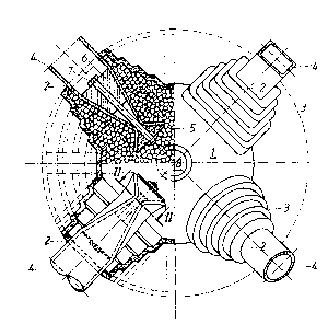
Figure 1 shows the joint connection in perspective, in
partial cross section along the axis of one rod joined to the con-
nection.
Figures2 to 4 show cross sections through various embodi-
ments of a detail of the joint connection on the line II-II in
Figure 1.
A joint connection comprises a metal casing 1 that has
a convex centre portion that is in the approximate shape of a
sphere. Projections 3 that taper down by steps to the openings 2
in the metal casing 1 extend in a star form from the centre portion.
In the right-hand, non-cross sectional portion of Figure 1, there
is an opening 2 for a rod 4, this being in the form of a rec-
tangular tube, and an additional opening 2 for a rod 4 in the form
of a round tube. An advantage of the ~oint connection according
to the present invention lies in the fact that the rods 4 do not
all have to be of the same cross section. Diagonal rods can be
lighter than main (chord, boom) rods.
In the left-hand portion of Figure 1 there are two rods
connected so as to form a joint; their axes lie in the plane of
the drawing. The filling within the metal casing 1 is indicated
in the upper part of the left-hand portion of Figure 1. This fill-
ing is not indicated in the lower part of the left-hand portion
of Figure 1, and the end section of the rod 4 that is arranged
: .
~ - 3 -

~2842S~
there is not shown in cross section.
It can be seen that the rods 4 end with a positive fit-
ting end section within the metal casing 1, this end section being
necked down. It can be seen from the cross section drawing of
the necked down end sections of rods 4 in Figures 2 to 4 that the
necked down sections are formed by crimping the walls of the tube
without any concomitant weakening or change in their cross sec-
tional area.
In each necked down end section of the rods 4 there are
two opposing conical expander elements 5, 6 on opposite sides of
the necked down sections. The necked down section is matched to
the shape of the expander element 5, 6. The two expander elements
5, 6 can be tightened against each other by means of a tension
element 7 that is located within the axis of the tube and is in
the form of a high tensile strength screw or a plurality of such
screws that are arranged so as to be longitudinally displaceable
within the end section of the rod, so that they lie closely again-
st the inner walls of the tube on opposite sides of the necked
down section.
On the top of the metal casing 1 there is a filler 8 for
filling said casing with hardenable filler substance.

Representative Drawing
A single figure which represents the drawing illustrating the invention.
Administrative Status

2024-08-01:As part of the Next Generation Patents (NGP) transition, the Canadian Patents Database (CPD) now contains a more detailed Event History, which replicates the Event Log of our new back-office solution.

Please note that "Inactive:" events refers to events no longer in use in our new back-office solution.

For a clearer understanding of the status of the application/patent presented on this page, the site Disclaimer , as well as the definitions for Patent , Event History , Maintenance Fee  and Payment History  should be consulted.

Event History

Description Date
Inactive: Adhoc Request Documented 1994-05-21
Time Limit for Reversal Expired 1993-11-23
Letter Sent 1993-05-21
Grant by Issuance 1991-05-21

Abandonment History

There is no abandonment history.

Owners on Record

Note: Records showing the ownership history in alphabetical order.

Current Owners on Record
"COMPROJECT" HANDELSVERTRETUNG UND TECHN. BURO FUR MASCHINENBAU FRANTL & CO. OHG
BEER, MANFRED
Past Owners on Record
ALBERT P. RAUNICHER
ERICH FRANTL
PETER HOFSTATTER
WERNER FRANTL
WILLIBALD ZEMLER
Past Owners that do not appear in the "Owners on Record" listing will appear in other documentation within the application.
Documents

To view selected files, please enter reCAPTCHA code :


To view images, click a link in the Document Description column. To download the documents, select one or more checkboxes in the first column and then click the "Download Selected in PDF format (Zip Archive)" or the "Download Selected as Single PDF" button.

List of published and non-published patent-specific documents on the CPD .

If you have any difficulty accessing content, you can call the Client Service Centre at 1-866-997-1936 or send them an e-mail at CIPO Client Service Centre.


Document
Description 
Date
(yyyy-mm-dd) 
Number of pages   Size of Image (KB) 
Abstract 1993-10-20 1 13
Cover Page 1993-10-20 1 12
Drawings 1993-10-20 1 38
Claims 1993-10-20 1 28
Descriptions 1993-10-20 4 129
Representative drawing 2002-01-07 1 23