Note: Descriptions are shown in the official language in which they were submitted.
DISK CARTRIDGE
BACXGROUND OF THE INVENTION
Field of the Invention
This invention relates to a disk cartridge comprisiny a
cartridge and a sheet-like recoxding medium which is rotatably
accommodated in the cartridge and fixed to the periphery of a
circular center plate, and the invention is best suited for
applying to a disk cartridge including a micro floppy disk, for
example, comprising a magnetic sheet having a diameter of 3.5
inches.
Description of the Prior Art
Figures 1 to 3 show a conventional disk cartridge
including a micro floppy disk and a driving device for rotating
the micro floppy disk.
As illustrated in Figures 1 and 2, a floppy disk 1
(simply dscribed as "disk" hereinafter) comprises a circular
center plate 2 of stainless steel or the like and a magnetic
sheet 3, namely, a sheet-like recording medium having a diameter
o 3.5 inches and fixed to the periphery of the circular center
plate 2, in which an almost square center hole 4 and an almost
rectangular eccentric hole 5 which is arranged aslant of the
center hole 4 at a predetermined angle are provided.
The disk 1 is rotatably accommodated in a cartridge 8
comprising an upper half 6 and a lower half 7 which are made of
synthetic resin, and the circular center plate 2 is loosely
fitted in a turntable insertion hole 9 which is provided in the
center portion of the lower half 7. A pair of upper and lower
head insertion holes 10 provided in the respective upper and
lower halves 6 and 7 along the radius direction of the magnetic
sheet 3 are openable and closable by the use of shutters ll.
The driving device is disposed in a disk player (not
shown) and comprises a turntable 15 which is so ixed to the
upper end portion of the shaft 14 of a motor 13 as to be
horizontally rotated. A magnetic chuck 18 comprising a yoke 16
and a magnetic plate 17 is secured to the upper side of the
turntable lS with screws 20 through a spacer 19, and a thin
slipper~ sheet 21 of nonmagnetic material is stuck in the center
portion of the upper face of the magnetic chuck 18. Furthermore,
a center pin 22, namely, the distal end of the. motor shaft 14
projects upwards from the magnetic chuck 18 in the center portion
thereof, and a driving pin 23 is provided apart from the center
o the magnetic chuck 18. The driving pin 23 is secured to a
leaf spring 24 sandwiched in between the magnetic plate 17 and
the spacer 19, and pro~ects upwards from the magne~ic chuck 18
through a through hole 25 the/eof.
As shown in Figure 1, when the cartridge 8 is
horizontally mounted o~ the turntable 15 under a state that the
shutter 11 is opened, the magnetic chuck 18 is inserted in the
-- 2 --
/
turntable insertion hole 9 as shown in Figure 2, and the circular
center plate 2 of the disk 1 is at~racted by the magnetic force
generated by the magnetic chuck 18 and horizontally located on
the slippery sheet 21. Simultaneously, the center pin 22 and the
driving pin 23 of the turntable 15 are ~itted into ~he cicular
circular center hole 4 and the eccentric hole 5 of the circular
center plate 2, respectively. As shown in Figure 3, a pair of
upper and lower magnetic heads 26 and 27 are inserted in the
respective insertion holes 10 and come in contact with the upper
and lower faces of the magnetic sheet 3 of the disk 1,
respectively.
When ~he motor 13 is started after the disk 1 is loaded
and the turntable lS is rotated, the circular center plate 2 is
positioned by the help of the center pin 22 and the torque for
rotating the circular center plate 2 is transmitted through the
driving pin 23, so that the magnetic sheet 3 is horizontally
rotated in the cartridge 8. Therefore, when the magnetic heads
26 and 27 are moved in the radius direction of the magnetic sheet
3, recording or reproducing is selectivcely performed on one of
double faces of the magnetic sheet 3.
In the meanwhile, the circular center plate 2 is so
~ormed by means o~ press work as to have a cylindrical portion 28
standing on the outer edge thereof and a ~lange portion 29
externally extending from the cylindrical portion 28 as shown in
Figure 3. A round hole 30 provided in the center portion of the
magnetic sheet 3 is put on the outer periphery of the cylinder
portion 28 so as to make the center of the magnetic sheet 3
coincide with the center of ~he circular center plate 2, and then
the portion 3a around the round hole 30 o~ the magnetic sheet 3
is stuck to the lower face of the flange portion 29 with an
adhesive 31.
Furthermore, a ring-like locating rib 32 having a large
diameter Dl is integrally formed with the upper half 6 in the
center portion of the inner face thereof as shown in Figure 3 and
is put within the inner periphery of the cylindrical portion 28
of the circular center plate 2 so as to position the magnetic
sheet 3 in the cartridge 8 lest the magnetic sheet 3 should
horizontally move over a predetermined extent in the cartridge 8
and as the result, the edge of the magnetic sheet 3 should come
in contact with the wall of the cartridge 8 to be broken. The
top of the center pin 22 of the turntable 15 abuts against the
slippery sheet 33 which is stuck to the inner face of the upper
half 6 as shown in Figure 3.
However, for fluctuations in thickness of the layer
formed by the adhesive 31, with which the portion 3a around the
round hole 30 of the magnetic sheet 3 is stuck on the lower face
of ~he flange portion 29 of the cixcular center plate 2 as shown
in Figure 3, or for other reasons, a height difference Hl arises
between the lower face 3b of the portion 3a around the round hole
30 and the upper face 27a of the lower magnetic head 27, which
functions as-a standard to determine the height of the magnetic
sheet 3. Thus, the horizontal upper face 27a of the lower
-- 4 --
_L~
magnetic head 27 can not wholly come into contact with the
magnetic sheet 3, and a deflection is generated in the radius
direction of the magnetic sheet 3, so that i~ makes bad contacts
between the magnetic heads 26, 27 and the magnetic sheet 3. Such
bad contacts particularly occur when the magnetic heads 26, 27
are moved to a position Pl where the magnetic heads 26, 27
approach nearest to the center of the circular center plate 2 for
recording or reproducing.
That is, the portion 3a around the round hole 30 of the
magnetic sheet 3 is fixed with the adhesive 31 to the lower face
of the flange portion 29 of the circular center plate 2, so that
it becomes more difficult to have the magnetic sheet 3 deflected,
as the magnetic head 26, 27 approaches to the ~lange portion 29
of the circular center plate 2 and the contact condition between
the magnetic heads 26, 27 and the magnetic sheet 3 becomes worst,
when the magnetic heads 26, 27 reaches the position Pl. As the
result, troubles, such as the aberration of tracking, the spacing
loss or the like are arroused. Particularly, such troubles give
great in1uence to the disk for high density recording, which has
a capacity of two mega bytes, as compared with the disk for
standard recording, which has a capacity of 1 mega bytes.
Therefore, if the diameter D2 ~ the circular center
plate 2 can be made much small in relation with the diameter D3
(= 3.5 inches) of the magnetic sheet 3, the above contacts are
improved, because the distance ~ between the positio~ Pl in
which the magnetic heads 26, 27 approach nearest to the flange
~'Lt~
portion 29 and a position P2 which coincides wi h the outer edge
of the fixed portion by the adhesive 31, the fixed portion being
in the portion 3a around the round hole 30 of the magnetic sheet
3, is made large enough. But to makè the diameter D2 small i5
not simply accomplished.
That is, in the conventional disk, the locating rib 32
having the large diameter Dl and integrally formed with the upper
half 6 is put within the inner periphery of the cylindrical
portion 28 of the circular center plate 2 so as to position the
magnetic sheet 3 in the cartridge 8, so that it is di~ficult to
change the diameter D2 of the circular center plate 2 below a
predetermined value. Thus, the diameter D2 of the circular
center plate 2 remains still large in relation with the diameter
D3 of the magnetic sheet 3.
OBJECTS AND SUMMARY OF THE INVENTION
Accordingly, it is an object of the present invention to
provide a disk cartridge in which the diameter of a circular
center plate can be made small enough in relation with the
diameter of a recording medium, such as the magnetic sheet or the
like, which is the same as before, by means of restricting the
movement of the circular center plate 50 as to position the
recording medium in a cartridge not on the peripheral side of the
circular center plate but on the central side thereof.
-- 6 --
A further object of the invention is to provide a disk
cartridge in which contacts of recording and/or reproducing
heads, such as magnetic heads or the like with a sheet-like
recording medium at the time of recording or reproducing can be
made much better than before, so that troubles, such as the
aberration of tracking, the spacing loss or the like are not
aroused and precision of recording and reproducing is much
improved.
Still another object of the invention is to provide a
disk cartridge best suited for high density recording, for
example, a micro floppy disk having a capacity of two mega bytes.
Still another object of the invention is to provide a
disk cartridge in which the stability of a circular center plate
on a turntable can be secured, even though the diameter of the
circular center plate is made small enough.
Still another ob~ect of the invention is to provide a
disk cartridge in which a stuck area of a sheet-like recording
meidum can be made large enough to stick fast the sheet-like
recording meidum to the flange portion of a circular center
plate, even though the diameter of the circular center plate is
made small enough.
Still another object of the invention is to provide a
disk cartridge in which a ring having a small diameter and so
fromed coaxially with a center hole of a circular center plate as
to surround the center hole so as to position a sheet-like
recording medium in a cartridge, can be simply made of synthetic
resin by outsert molding.
Still another object of the invention is to provide a
disk cartridge in which a ring having a small diameter, made of
synthetic resin, and so formed by outser molding as to surround
a center hole of a circular center plate, can be s~uck very fast
to the circular center plate.
BRIEF DESCRIPTION OF THE DRA~INGS
Figure 1 is a perspective view of a conventional disk
cartridge;
Figure 2 is a sectional side view of the principal
portion of the disk cartridge of Figure l;
Figure 3 is a sectional view of the principal portion of
the disk cartridge of Figure 1 on an enlarged scale;
Figure 4 is a sectional side view of a disk cartridge on
an enlarged scale according to an embodiment of this invention;
Figure 5 is a perspective view of the principal portion
o the disk cartridge of Figure 4;
Figure 6 is a sectional side view of a disk cartridge
according to a second embodiment of this invention; and
Figure 7 is a sectional side view of a disk cartridge
according to a third embodiment of this invention.
DETAILED DESCRIPTION OF PREFERRED EMBODIMENTS
Firstly, a first embodiment of this invention applied to
a disk cartridge including a micro floppy disk will be described
hereinafter by reference to Pigures 4 and 5. In the drawings,
the same parts in the constitution as those shown in Figures 1 to
3 will be denoted by the same reference numerals and will not be
explained.
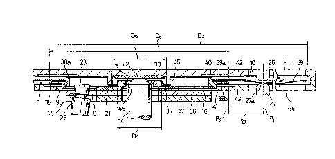
A circular center plate 36 of a disk 1 is made o~ metal,
such as strainless steel or the like. A ring 37 having a small
diameter D4 and made of synthetic resin, such as ABS resin or the
like is formed integrally by outsert molding with a wall on the
outer surface thereof, the wall projecting upwards from the
circular center plate 36 and forming a center hole 4 of almost
square shape, and the ring 37 being provided coaxially with the
center hole 4. In the wall of the circular center plate 36,
there is provided a joining portion 46, such as the hole or the
recess so as to make the ring 37 stick to the circular center
plate plate 36 as firm as possible.
Furthermore, a flange 38 made of sythetic resin, such as
A~S resin or the like is so formed integrally by outsert molding
with the circular center plate 36 on the outer edge thereof as to
project upwards from the circular center plate 36and extend
horizontally. A round hole 40 provided in the center portion of
a sheet-like recording medium, namely, a magnetic sheet 39 having
a diameter o~ 3.5 inches is put on the outer periphery of a
cylindrical portion 38a which projects upwards from the flange 38
on the fixed end thereof so as to make the center of the magnetic
sheet 39 coincide with the center of the circular center plate
36, and then a portion 39a around the round hole 40 of the
magnetic sheet 39 is stuck to the upper face of the flange 38
with an adhesive 41 or the like.
_ g _
The disk 1 is rotatably accommodated in a cartridge 44
comprising an upper half 42 and a lower hal~ 43 and made of
synthetic resin. The circular center plate 36 is loosely fitted
in a turntable insertion hole 9 provided in the lower half 43. A
cylindrical locating rib 45 having a small inside diameter D5 (~
D4) is integrally formed in the center portion of the inner face
thereof. The ring 37 of the circular center plate 36 of the disk
1 having a small diameter D4 is put within the inner periphery of
the locating rib 45 having a small diameter D5 so as to have the
magnetic sheet 39 positioned in the cartridge 44. Of course, the
diameter of the locating rib 45 is to be determined lest the
locating rib 45 should interfere with the driving pin 23 of the
turntable 15, and also, the inside diameter of the flange 38 is
to be determined lest the flange 38 should interfere with the
eccentric hole 54 of the circular center plate 36.
In the embodiment, the ring 37 having the small diameter
D4 and stuck to the circular center plate 36 in the vicinity of .. .
the center thereof is put within the inner periphery of the
locating rib 45 having the small inside diameter D5 and formed
integrally with the upper half 42 on the inner ace thereof so as
to have the magnetic sheet 39 positioned in the cartridge 44.
Therefore, as shown in Figure 4, the diameter D6 of the
flange 38 can be made small enough in relation to the diameter
D3 (= 3.5 inches) of the magnetic sheet 39, and the distance ~2
between the outer edge.P3 of the fixed portion included in the
portion 39a around the round hole 40 of the circular center plate
-- 10 --
\
~!L~ 3
36 and stuck to the flnage 38 on the upper face thereof, and the
position Pl (the same as before), where the magnetic heads 26, 27
are approached nearest to the center of the circular center plate
36 for recording or reproducing is made large enough. In other
words, between D6, ~2 shown in Figure 4 and D2, ~1 shown in
Figure 3, there are relations D2 > D6, so that Q2 is larger than
by the difference between D2 and D6.
According to this invention, the contact condition of
the magnetic sheet 39 with the magnetic heads 26 and 27 is much
improved even when the height difference Hl arises between the
lower face 38b of the portion 39a around the roung hole 40 of the
magnetic sheet 39 and the upper face 27a of the lower magnetic
head 27 that functions as a standard to determine the height of
the magnetic sheet 39 due ~o, for example, the fluctuation of the
thickness of the adhesive layer, through which the portion 39a
around the round hole 40 is stuck to the upper fa~e of the flange
38 of the circular center plate 36, because the distance R2 is
made large enough. Thus, the troubles, such as the aberration of
tracking, the spacing loss or the like are not aroused.
Figures 6 and 7 show other embodiments concerning the
portion of the circular center plate to which the magnetic sheet
is fixed. In the followiny description, the same parts in the
constitution as those shown in Figures 1 to 5 are denoted by the
same reference numerals so as to omit the explanation therefor.
Shown in Figure 6 is a circular center plate 50 similar in
appearancè to the circular center plate 36 shown in Figure 5. In
the circular center plate 50, a cylindrical portion Sl thereof
has a smaller diameter Dlo, but the width w of a flange portion
52 thereof is the same as before, so that a magnetic sheet 49 is
stuck fast to the circular center plate 50 by the help of an
adhesive 53. But the circular center plate 50 on the turntable
15 becomes worse in stability as the diameter D1o of the
cylindrical portion 51 is made small. Hence, a ring 54 made of
synthetic resin, formed on the periphery of the cylindrical
portion 51 by outsert molding, and having a ~7idth n and a
diameter Dll is provided so as to improve the stability of the
circular center plate 50 on the turn table 15.
In Figure 7, the diameter of a cylindrical portion 56 of
a circular center plate 55 is not decreased. Instead, the width
w of a flange portion 57 of the circular center plate 55 is
decreased so as to make the diameter of the circular centex plate
55 smaller. But due to the narrow width w of the flange portion
57, the stuck area in the magnetic sheet 60 is too small to make
the magnetic sheet 60 stick fast to the circular center plate 55.
Such being the case, a ring 58 made of synthetic resin and having
a stuck portion 61 of a width s is formed integrally by outsert
molding with the circular center plate 55 on the inner periphery
of the cylindrical portion 56 thereof, and the magnetic sheet 60
is stuck in width r (= w ~ s) by the help of an adhesive 59, so
that the magnetic sheet 60 is steadily integral with the circular
center plate 55.
- 12 -
Although illustrative embodiments of the invention have
been described in detail herein with reference to the
accompanying drawings, it is to be understood the invention is
not limited to such precise embodiments, and that various changes
and modifications may be effected therein. For example, the ring
37 is not necessarily formed by outsert molding as described in
the embodiments. It can be secured to the circular center plate
36 by means of adhesion, weld, screws or the like. Further, the
sheet-like recording medium can be other than the magnetic sheet.
This invention is applied to not only the disk cartridge
including the micro floppy disk but also a disk cartridge
including a recording medium which is used under various types of
recording or reproducing.
13 -