Note: Descriptions are shown in the official language in which they were submitted.
--1--
FILLING AND DISPENSING YALVE WITH DROP-AWAY VALVE MEMBER
BACKGROUND OF THE INVENTION
1. Field of the Invention
This invention relates to an improved valve of the
general type described in the above related application,
in which the valve is used both for filling a container
with liquid and for dispensing the liquid from the con~
tainer. More particularly, it relates to a valve of this
type in which multiple flow paths used during the filling
and the dispensing are formed from parts having a simpli-
fied construction, compared to the specific form of thevalves shown in the above application.
2. Description of the Prior Art
The extensive prior art on valves used in packages
for liquid products is summarized and of record in the
above related application. The shortcomings of earlier
valve designs for potential alternative packages for draft
A-46342/WEH
~P
2 61051-2189
beer to the traditional keg led to the development of the beer
valves described in the related application. While the multiple
flow path beer valve designs shown in the related application have
been found to be hiyhly suitable for their intended purpose,
further development has been found desirable in order to make
valves of this qeneral type simpler in design, easier to fabricate
in high volume production, and therefore lower in cost.
SUMMARY OF THE INVENTION
Accordingly, it is an object of this invention to
provide a multiple flow path filling and dispensing valve for a
liquid that is especially suited for fabrication in high volume
production.
It ls another object of the invention to provide such a
multiple flow path filling and di~pensing valve which incorporates
an improved technique for sealing at least one of the multiple
flow path~ after filling and for opening the at least one flow
path for dispensing the liquid from a container on which the valve
is used.
It is a further object of the invention to provide such
a multiple flow path filling and dispensing valve incorporating an
improved way for locking the valve open for dispensing and after
the container is empty which will allow the valve to be opened
more than once before it is permanently locked open.
The attainment of these and related objects may be
achieved through use of the novel valve and package incorporating
the valve herein disclosed.
3 61051-2189
In accordance with a broad aspect of the invention there
is provided a filling and dispensing valve, which comprises a
valve housing having a central passage extending axially through
said valve housing, means in said valve housing for forming a
second passage extending through said valve housing, a first valve
mem~er configured for sealing engagement of said central passage,
and a second valve member configured for sealing engagement of
said second passage, at least one of said first and second valve
members and at least one of said central and second passages being
configured so that said at least one of said first and second
valve members is urged into sealing engagement with at least one
of said central and second passages by internal pressure in a
container on ~,7hich said valve is provided, at least one of .said
first and ~econd valve members and said valve housing being
configured so that said at least one of said first and second
valve members will drop away from said at least one of said
central and second passages when the pressure in the container is
insufficient to hold said at least one of said first and second
valve members in sealing position against said at least one of
said central and second passages to leave said valve in a
permanently open state.
In accordance with another broad aspect of the invention
there is provided a filling and dispensing valve, which comprises
a valve housing having a central passage extendin~ axially through
said valve housing, means in said valve housing for forming a
second passage extending through said valve housing, a valve
member configured for sealing engagement of said central passage,
.. .
~L 2 ~ ~ ~ 7r~
3a 61051-218~
said valve member being configured so that said valve member is
urged into sealing engagement with said central passage by
internal pressure in a container on which said valve is provided,
said valve member and said valve housing being configured so that
said valve member ~ill drop away from sealing engagement with said
central passage when the pressure in the container is insufficient
to hold said valve member in sealing position against said central
passaqe.
In another aspect of the invention, a filling and
dispensing valve includes a valve housing having a central passage
extending axially through the valve housing. A means is provided
in the valve housing for forming a second passage extending
through the valve housing. A valve member is configured for
sealing engagement of the central passage. The valve member is
conflgured so that the valve member is urged into sealing
engagement with the cen~ral passage by lnternal pressure in a
container on which the valve is provided. The valve member has at
least one flexible, flared projection extending laterally from the
valve member and away from an end of the valve configured for
placement inside a container. The flexible, flared projection is
configured to engage a wall of the central passage in the sealing
engagement up to a given pressure in the container and to flex
away from the wall at a pressure greater than the given pressure.
In accordance with another broad aspect of the invention
there is provided a filling and dispensing valve, which comprises
a valve housing having a central passage extendlng axially through
said valve housing, means in said valve housing for forming a
~L2~ '.Z
3b 61051-2189
secc,nd passage extending through said valve housing, a first valve
member configured for sealing engagement of said central passage,
a second valve member configured for sealing engagement of said
second passage, and a mechanism for locking one of said first and
second valve members in an open position, said mechanism
c~mprising back-to-back ratchets and pawls on a wedge member, said
one of said first and second valve member, and a fixed member
positioned opposite said one of said first and second valve
members from said wedge member, said back-to-back ratchets and
pawls being configured to advance said wedge downward as said
valve is opened and closed until it reaches a position that
prevents said one of said first and second valve members from
returning to the sealed position against the wall of one of said
central and ~econd passage6.
In accordance with another broad aspect of the invention
there is provided a valve, which comprises a valve housing having
a central passage extending axially through said valve housing, a
valve member configured for sealing engagement of said central
passage, said valve member and central pa6sage being configured so
that said valve member is urged into sealing engagement with said
central passage by internal pressure in a container on which said
valve is provided, and a down tube communicating with said central
passage and attached to an end of said housing configured for
placement inside a container to extend proximate to a bottom of
the container, said down tube being oriented at an inclined angle
with respect to an axially extending direction of said housing
such that an end of said down tube remote from said housing will
L2~
3C 61051-2189
be at a side of the container and proximate to the bottom of the
cont;ainer.
The attainment of the foregoing and related objects,
advantages and features of the invention should be more readily
apparent to those skilled in the art, after review of the
following more detailed description of the invention, taken
together with the drawings, in which:
BRIEF DESCRIPTION OF T~E DRAWINGS
Figure 1 is an exploded, partial cross section and
perspective view of a first valve in accordance with the
invention.
Figure 2 is a cross section view of the valve of
...
~ . .
~L~ 3L'~
--4--
Figure 1 during filling of a container including the
valve.
Figure 3 is another cross-section view of the valve
in Figures 1 and 2, showing position of its parts after
filling of the container has been completed and prior to
dispensing liquid from the container through the valve.
Figure 4 is a further cross-section view of the valve
in Figures 1-3, but while dispensing liquid from the
container through the valve.
Figure 5 is a cross-section view of a second valve in
accordance with the invention.
Figure 6 is an exploded cross-section view in partial
section of a third valve in accordance with the invention.
Figure 6A is an exploded cross-section view of the
valve in Figure 6.
Figure 7 is an assembled cross-section view of the
valve in Figure 6 and 6A when sealed.
Figures 7A and 7B are additional assembled
cross-section views of the valve in Figures 6-7, but in
later stages of operation.
Figure 8 is a cross-section view of the valve in
Figures 6-7B, but in the open position.
Figures 8A and 8B are additional cross-section views
of the valve in Figures 6-8 in the open position, but in
later stages of operation.
Figure 9 is a cross-section plan view of the valve in
Figures 6-8B.
Figure 9A is a top plan view of a portion of the
valve in Figures 6-9.
Figure 9B is a side elevation view of the valve
portion shown in Figure 9A.
Figures 9C and 9D are side views of the valve portion
shown in Figures 9A and 9B.
Figure 10 is an exploded cross-section view of a
fourth valve in accordance with the invention.
Figure 11 is a cross-section view of the valve in
Figure 10 when sealed.
A-46342/WEH
-5-
Figure 12 is a cross-section view of the valve in
Figures 10 and 11, but while dispensing liquid from a
container in which the valve is used.
Figure 13 is a side view of a package incorporating
the valve of Figures 10-12.
DETAILED DESCRIPTION OF THE INVENTION
Turning now to the drawings, more particularly to
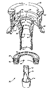
Figures 1-4, there is shown a valve 20 in accordance with
the invention. The valve 20 has three parts: a valve
housing 22, a poppet type valve member 24 and an annular
valve member 26. These parts are advantageously fabricat-
ed from a suitable molded plastic material, such as an
injection molded co-polyester plastic. Similarly, the
parts of the other examples of valves described below are
also advantageously formed by injection molding of a
co-polyester plastic.
Valve housing 22 has a centrally disposed, axial
passage 28 extending frcm its top 30 through the housing
22 and terminating in a flanged end 32. A down tube 34 is
attached to the flanged end 32 of the housing 22, such as
by a press fit, ultrasonic bonding or spin welding, and
extends from the flanged end 32 down to the bottom of a
container 36 (Figure 2) on which the valve 20 is mounted.
The poppet valve member 24 is positioned within the
passage 28 when the valve 20 is closed (see Figure 3).
The poppet valve member 24 has a cruciform cross section
rod 52 and a flared projection 54 extending laterally and
upwardly from base 56. The flared projection 54 engages
wall 58 of the passage 28 to seal the passage 28 when the
valve 20 is closed. A branch passage 38 is connected to
the passage 28 by circumferential openings 40 around the
passage 28. The annular valve member 26 fits into the
branch passage when the valve is closed (see Figure 3).
The annular valve member 26 has a ring portion 42 and
flared projections 44 and 46 extending laterally and
A-46342/WEH
--6--
upwardly from the ring portion 42. As is best shown in
Figure 3, the flared projections 44 and 46 engage opposing
walls 48 and 50 of the valve housing 22 which define the
branch passage 38 when the valve is closed.
Figure 2 shows the valve 20 during filling of the
container 36 on which the valve 20 is mounted. Filling is
carried out with the container 36 inverted. A filling
head 60 is inserted into the passage 28 from top 30 of the
valve housing 22. A bayonet fitting 62 engages recess 64
on the housing 22. ~he filling head has an outer tube 66
through which beer flows into the container 36 and an
inner tube 68 through which air flows out of the container
36 as the beer fills the container 36. Outer tube 66 has
a gasket 70 which engages projection 72 of the housing 22
to seal the outer tube 66 against the housing 22. Inner
tube 68 extends beyond the outer tube 66 to engage rod 52
of the poppet 24 when the filling head 60 is in place in
the passage 28, thus moving the poppet upward as shown to
displace the projection 54 away from the wall 58. A
gasket 7g on the inner tube 68 engages the housing 22 at
76 to seal the inner tube 68 against the housing 22. When
beer is supplied to the outer tube 66 for filling the
container 36, the pressure of the beer in the branch
passage 38 lifts the annular valve member 26 so that the
flared projections 44 and 46 are no longer engaging walls
48 and 50 of the branch passage 38. This opens a flow
path 78 for the beer through the branch passage 38 and
into the container 36. As the beer fills the container
36, air trapped in the container 36 is forced out of the
container 36 in a second flow path 80 through the central
passage 28. When the container 36 has been filled, it is
has an internal pressure of about 15 p.s.i. The flow of
beer into the container 36 is turned off, the annular
valve member 26 settles into sealing position (see ~igure
3), and the filling head 60 is removed simultaneously with
righting the container 36. The internal pressure of the
beer and any remaining trapped air inside the container 36
A-46342/WEH
keeps the annular valve member in sealing positicn and
causes the poppet 24 to move into sealing position in the
central passage 28 as the filling head 60 is withdrawn
from the passage 28. The valve 20 on the filled container
36 then has its valve members 24 and 26 in the positions
shown in Figure 3.
The configuration of the projections 44 and 46 on the
annular valve member 26 and the projection 54 on the
poppet 24 provide an important safety feature in the valve
20 when the valve is in its sealed position as shown in
Figure 3. At the pressures normally employed with draft
beer, e.g., about 15 p.s.i, the projections 44, 46 and 54
provide an effective seal in the valve 20. As the pres-
sure increases up to a certain level, e.g. about
p.s.i., the seal becomes even more effective as the
projections 44, 46 and 56 are pressed tighter against
their mating walls 48, 50 and 58. Above about p.s.i.,
flexibility of the projections 44, 46 and 54 allows a
blow-by effect to occur for the relief of excess pressure.
When the excess pressure has dropped sufficiently, an
effective seal is once again created. The pressure at
which the blow-by effect takes place is dependent on the
thickness and flexibility of the projections 44, 46 and
56, and can be adjusted with different thicknesses and/or
materials for the projections.
Figure 4 shows the valve 20 during dispensing of the
beer from the container 36. A tapper 82 is inserted into
the valve 20 from its top 30. End 84 of the tapper 82
extends into the passage 28 to dislodge the poppet 24 (not
shown), causing it to fall to the bottom of the down tube
34 and allowing an initial flow of beer from the container
36 in flow path 86. A spigot (not shown) is provided at
the upper end of the flow path 86 for controlling flow of
the beer from the container 36. As in the case of the
3~ filling head 60, the tapper 82 has a gasket 88 which seals
against the passage 28 at 76 and a gasket 90 which seals
against projection 72 on the valve housing 22. Bayonet
A-46342/WEH
--8--
fitting 92 engages recess 64 on the housing 22. Inner
beer flow tube 94 of the tapper has a flange 96 with an
O-ring 98 in sealing engagement against housing 100 of the
tapper 82. An air inlet 102 extends through the housing
100 below the flange 96. When air is supplied through the
inlet 102 at a pressure greater than the internal pressure
of the container 36, it blows the annular valve member 26
out of sealing engagement with the branch passage 38. The
annular valve member 26 then falls to the bottom of the
container 36, and both air flow path 104 and beer flow
path 86 of the valve 20 are permanently open. When the
beer has been emptied from the container 36, the tapper 82
is removed. Because the air and beer flow paths 104 and
86 of the valve 20 remain open when this is done, there is
no danger of excessive pressure building up in container
36 when it is crushed for recycling.
Figure 5 shows another valve 110 incorporating a
central passage 112 and a branch passage 114 in valve
housing 116. A gasket 118 in the central passage 112 has
an O-ring 120 in sealing engagement against wall 122 of
the central passage 112. A spring 124 extends between the
gasket 118 and step 126 in the central passage. The
gasket 118 engages an end of a tapper (not shown~ when the
tapper is inserted in top 128 of the valve housing 116.
The spring loaded gasket 118 allows the valve 110 to be
used with common commercially available tappers. A poppet
and an annular valve member having the same configuration
as the poppet 24 and annular valve member 26 of the
Figures 1-4 embodiment completes the valve 110. Other
than as shown and described, the construction and opera-
tion of the valve 110 is the same as the valve 20 of the
Figures 1-4 embodiment.
Figures 6-8 show another beer filling and dispensing
valve 130 having a poppet 132 in a central passage 134 of
a valve housing 135, a branch passage 136 connected to the
central passage 134 by centrifugal apertures 137, and a
sealing member 138 for the branch passage 136 configured
A-46342/WEH
.2
g
as a flanqe for down tube 140. The flange sealing member
138 has a portion 142 extending above the down tube 140
into cylinder 143 and defining the central passage 134 in
part. The poppet 132 has a projection 148 extending
laterally and upwardly to engage the inclined wall 146 to
seal the central passage when pressure inside the contain-
er 36 forces the poppet 132 upward in the portion 142.
Similarly, sealing member 138 has a projection 150 extend-
ing laterally and upwardly to engage wall 152 of the
10 branch passage 136. The projections 148 and 150 interact
with their mating surfaces 146 and 152 in the same manner
as the projections 44, 46 and 54 and their mating surfaces
48, 50 and 58 in the Figures 1-4 embodiment to provide
effective sealing up to a certain pressure and blow-by
15 pressure relief above that pressure.
The valve 130 incorporates a ratchet mechanism 162
(Figure 7) which allows the valve 130 to be opened and
closed more than once before the ratchet mechanism 162
keeps the valve 130 permanently open. Flange 138 attached
20 to down tube 140 has the portion 142 extending above the
down tube 166 to define central passage 134 in the housing
172 in part. The portion 142 has a plurality of ratchet
teeth 164 extending circumferentially around the portion
142 below projection 154. Cylinder 143 has a pair of
25 pawls 166. A wedge 168 (see also Figures 9A-9D) is
inserted between the teeth 164 and pawls 166. The wedge
168 has ratchet teeth 170 which engage the pawls 166 and a
pawl 172 which engages the ratchet teeth 164. It can be
seen that the ratchet teeth 164 and 170 and the pawls 166
30 and 172 form back-to-back ratchet and pawl mechanisms.
These back-to-back ratchet and pawl mechanisms operate to
advance the wedge 168 downward each time the valve 130 is
opened and closed, until bottom 174 of the wedge 168
bottoms out on surface 176, at which time the valve 130
35 remains in a permanently open position for pressure
relief. This mode of operation can be better understood
by following the sequence of operation show~ in Figures
A-46342/WEH
--10--
7-8B .
Figure 7 shows the valve 130 in its sealed position,
after assembly and before the container 36 has been filled
with beer. In assembly, the wedge 168 is driven between
the portion 142 and the ring 143 opposite pawl 166 until
pawl 172 engages the first tooth 164 on the portion 142.
For the valve to be in the position shown in the absence
of internal pressure in the container 36 for holding the
poppet 132 in its sealed position, the container 36 needs
lO to be in an inverted position, so that gravity will hold
the poppet 132 in the position shown.
For testing operation of the valve 130, it is opened
for the first time to the position shown in Figure 8. A
testing head 180, which may be a tapper as shown, pushes
15 down on the projection 154 to move the flange 138 and down
tube 140 to the position shown. Tube 181 is inserted in
housing 183 of the testing head until end 182 of the tube
181 pushes down on the poppet 132 to dislodge it from the
inclined surface 146, and it falls to the bottom of the
20 down tube 140. The pawl 166 moves over the first tooth
170 on the wedge 168, as can be seen by comparing Figures
7 and 8. A bayonet fitting at 185 secures the head 180 in
place, and gasket 183 forms a seal with the valve housing
135. Gasket 184 separates the central passage 134 from
25 the branch passage 136. Air is then introduced into the
container 36 from air inlet 186 through branch passage 136
and flow through the down tube and out of the container 36
is checked. With the tube 181 in place, even though the
air flow will raise the poppet against end 182, the valve
30 remains open. To test sealing of the poppet 132 against
surface 146, the tube 181 is raised in housing 183 until
projection 148 of the poppet 132 is allowed to move into
sealing engagement against the surface 146.
When the testing has been completed, the head 180 is
35 removed from the valve 130. Positive pressure inside the
container 36 returns the flange 138 with the projection
150 in sealing engagement against inclined surface 152.
A-46342/WEH
--11--
The pawl 172 on wedge 168 moves over the first tooth 164
on portion 142 during the upward movement of the flange
138 (compare Figures 8 and 7A).
For filling the container, as shown in Figure 8A, a
filling head 190 is attached to the valve 130 in the same
manner as the testing head 180. Gasket 192 seals the
central passage 134 from the branch passage 136. The
filling head pushes down on the projection 154 to move the
flange 138 down, opening branch passage 136. This move-
10 ment advances pawl 166 over the second tooth 170 (compare
Figures 8A and 7A). Tube 194 is lowered in housing 196 to
push down on poppet 132, which falls to the bottom of down
tube 140. The beer flows into the container 36 through
branch passage 136 and the air in the container is ex-
15 pelled through the down tube 140 and central passage 134.
The poppet moves upwa~d in the down tube 140 with the air
flow, but is prevented from sealing the central passage
134 by the tube 194. The container 36 can be filled
either right side up or inverted with the valve 130. When
20 the container 36 has been filled, the tube 194 is raised
in housing 196 to allow the poppet 132 to seal the central
passage 134,
When the filling head 190 is removed, positive
pressure in the container 36 returns the flange 138 to the
25 sealed position shown in Figure 7B, again sealing the
branch passage 136. Pawl 172 moves over the bottom tooth
164 during this movement (compare Figures 7B and 8A).
Note that bottom 174 of the wedge 168 engages surface 176
of the flange 138 for the first time.
Figure 8B shows ~he final actuation of the valve 130
for dispensing beer from *he container 36. A tapper 200
is attached to the valve 130 in the same manner as the
testing head 180 and the filling head lgO. Downward force
on the flange 138 moves the flange and down tube 140 down,
opening the branch ~assage 136. During this downward
movement, pawl 166 moves over the top tooth 170 on the
wedge 168. The pawls 166 and 172 now lock the flange and
A-46342/WEH
-12-
down tube 140 in the position shown. Tube 202 pushes down
on the poppet 132 to open the central passage 134, and
beer may flow out of the container 36. The tube 202
prevents poppet 132 from being raised to sealing position
by the beer flow. For dispensing beer from the container
36, air or carbon dioxide is supplied under pressure
through the branch passage 136 by the tapper 200, and the
beer flows out through the down tube 140 and central
passage 134. When the container is empty, the tapper 200
is removed, and the flange 138 remains locked in the open
position as shown by the wedge 168. Pressure buildup is
thus avoided in the container 36 when it is crushed for
recycling. Other than as shown and described, the con-
struction and operation of the Figures 6-8B embodiment is
the same as that of the Figures 1-4 embodiment.
Figures 10-12 show a valve 190 having one moving
part, in the form of a poppet 192 with a flange 193 which
engages inclined wall 194 of central passage 196 extending
through housing 198 when the valve 190 is closed. As in
the case of the Pigures 1-4 embodiment, the container 36
using the valve 190 must be filled in the inverted posi-
tion. The valve 190 has a canted down tube 200, which
reaches the lowest point of the container 36 when the
container 36 is resting on its side, such as when it is
placed in a refrigerator for dispensing beer without
removing the container from the refrigerator, as shown in
Figure 13. Central passage 196 has apertures 202 extend-
ing through wall 204 above the down tube 200. Figure 11
shows the valve 190 in its sealed position, with poppet
192 held in place with flange 193 in sealing engagement
against the inclined wall 194 by the internal pressure of
about 15 p.s.i. in the container 36 after it has been
filled with beer. Pigure 12 shows the valve 190 after
installation of a tapper 206 for dispensing the beer from
the container 36. The tapper 206 has an inner tube 208
with an O-ring 210 which is inserted past the apertures
202 and seals against fitting 212 for the down tube 200.
A-46342/WEH
~L?v~
-13-
The tapper 206 has an outer tube 214 with an O-ring 216
that seals against wall 217 of the central passage 196.
An air flow path 218 is thus created between the inner and
outer tubes 208 and 214, in the central passage 196
5 outside inner tube 208 and through apertures 202 into the
container 36. The beer flow path 220 is through the down
tube 200 and the inner tube 208 of the tapper 206.
It should now be readily apparent to those skilled in
the art that a novel filling and dispensing valve and
package capable of achieving the stated objects of the
invention has been provided. The valve incorporates
drop-away valve members to prevent excess pressure from
building up after the container has been emptied by
leaving the valve permanently open, such as when a package
incorporating the valve is crushed, and/or blow-by sealing
projections for release of excess pressure when the valve
is closed. In another form of the invention, a ratchet
mechanism is used to allow the valve to be opened and
cloced several times before it locks in the open position.
The valve i5 simple in construction, 80 that it is easily
fabricated under high volume manufacturing conditions.
It should further be apparent to those skilled in the
art that various changes in form and details of the
invention as shown and described may be made. For exam-
ple, the air and beer flcw paths of the valves as depictedcould be interchanged with minor changes in the construc-
tion of the valves and their associated filling heads and
tappers. It is intended that such changes be included
within the spirit and scope of the claims appended hereto.
A-46342/WEH
.