Note: Descriptions are shown in the official language in which they were submitted.
~2~ 6
PRE-PACK DISPLAY STAND AND
METHOD OF ERECTION
BACKGROUND OF THE INVENTION
1. Field of the Invention
This invention generally relates to a pre-pack
display stand and, more particularly, to a method of
erecting the same.
2. Description of Related Art
Pre-pack display stands are known in which a
tray is packed in advance with articles to be displayed.
A discrete stand is typically erected ~n situ at a retail
establishment. Thereupon, the pre-pack tray is placed
on the erected stand in order to display the articles
contained therein.
Although generally satisfactory for its in-
tended purpose, experience has shown that the known pre-
pack display stands possess many disadvantages. First
of all, it is very time-consuming for store personnel to
erect a stand, and particularly so in the case where the
personnel have not been previously trained in the correct
procedure of erecting the stand. Secondly, since the
stand and the tray are separate items, they are prone
to being misplaced or lost. They also must be separately
inventoried, shipped and paired together at the retail
establishment. In additicn, the tray can fall off the
~L2~ a ~;
stand, thereby spilling the articles.
It is also known to automatically erect dis-
play stands which are not of the pre-pack type. See, for
example, U.S. Patent Nos. 4,493,424 and 4,570,805 and
reissue patent RE. 32,668.
SUMMARY OF THE INVENTION
In accordance with an aspect of the invention, a
display stand, comprises:
(a) a pre-pack tray in which articles to be
displayed are packed;
(b) a base erectable from a collapsed to an erect
condition;
(c) means connecting the tray to the base for
movement among a compact storage position in which the
tray rests on and maintains the base in the collapsed
condition, a lifted position in which the tray is raised
above the base, and a lowered position in which the tray
is lowered onto the base in the erect condition;
(d) means on the base for automatically erecting the
base to the erect condition in the lifted position of the
tray; and
(e) means on the base for supporting the tray on the
base in the lowered position of the tray.
In accordance with another aspect of the invention,
2S a method of erecting a pre-pack display stand, comprises
the steps of:
(a) pre-packing articles to be displayed in a
tray;
(b) collapsing a foldable base to a collapsed
condition;
(c) connecting the tray to the base;
(d) resting the tray on the collapsed base to
maintain the base in the collapsed condition;
(e) lifting the tray from the collapsed base
while maintaining the tray connected to the base;
(f) automatically erecting the base to an erect
condition while the tray is lifted above the base; and
1 ,,.!,
,
(g) lowering the tray onto the base to support
the tray in the erect condition.
In keeping with these aspects of the invention and
others which will become apparent hereinafter, one
feature of this invention resides, briefly stated, in a
display stand comprising a pre-pack tray in which
articles to be displayed are packed, and a base erectable
from a collapsed to an erect condition. The tray is
connected to the base for movement among a compact
storage position in which the tray rests on and maintains
the base in the collapsed condition, a lifted position in
which the tray is raised above the base, and a lowered
position in which the tray is lowered onto the base in
the erect condition. The base is automatically erected
to the erect condition in the lifted position of the
tray. Means are provided on the base for supporting the
tray thereon in the lowered position of the tray.
Hence, in accordance with this invention, the
pre-pack display stand is erected in the following
manner:
First, the pre-pack tray is lifted from the
base in the collapsed position in which the tray main-
tained the base. The base is automatically erected while
the tray is lifted above the base. After the base has
erected itself, the tray is lowered onto the base,
whereupon the erected base supports the tray.
Thus, the pre-pack stand of this invention
is automatically, quickly and efficiently erected. The
time spent and the skil7 involved in erecting the stand
are at a minimum. It is no longer necessary to separ-
ately inventory, ship or match separate trays and stands,
since, as stated above, the tray and stand of this in-
vention are interconnected, preferably by a hinge panel.
In accordance with a preferred construction,
the base has front and rear panels lying substantially
flat against each other in the collapsed condition, and
movable away from each other in mutual parallelism during
erection of the base to the erect condition. ~he base
also has side panels extending between the front and
rear panels at opposite sides of the stand. Each side
panel has a pair of side panel portions which lie sub-
stantially flat against each other inthe collapsed con-
dition, and which are out-folded into a coplanar state
during erection of the base. A pair of support panels
are provided on the base, the support panels being mov-
able toward each other into a common plane during erec-
tion of the base. Means are provided for constantly
biasing the support panels tGward each other. Prefer-
ably, a circumferentially complete elastomeric band has
opposite arcuate ends received in respective slots
formed in the support panels. In the collapsed condi-
tion, the band is stretched to a high-tensioned state.
~l2~
In the erect condition, the band is returned to a less-
tensioned state. All of the aforementioned panels are
flat and juxtaposed with one another in the collapsed
condition. The tray is advantageously provided with a
flat-bottom panel lying substantially flat against the
flattened panels of the base in the collapsed condition.
The support panels have first upper support
surfaces. The front, rear and side panels have second
upper support surfaces which, together with the first
upper support surfaces, substantially lie in a support
plane on which the flat-bottom panel of the tray support-
ably rests. The tray has a front border panel, as well
as rear and side border panels, each extending generally
normally of the bottom panel thereof. The side panels
of the base have notches ln which the front border and
bottom panels of the tray are at least partially support-
ably received. A locking flap may be provided on and
extend above the front panel. The locking flap engages
the front border panel and assists in preventing the
tray from falling off the base.
The tray is connected to the base by connect-
ing means, including a hinge flap or panel. The hinge
flap has one hinge section secured to the base, and an
opposite hinge section secured to the bottom panel of
the tray. These hinge sections are pivotable relative
to each other about a hinge axis among the aforementioned
tray positions.
~2~
",
The novel features which are considered as
characteristic of the invention are set forth in parti-
cular in the appended claims. The invention itself,
however, both as to its construction and its method of
operation, together with additional objects and advan-
tages thereof, best will be understood from the follow-
ing description of specific embodiments when read in
connection with the accompanying drawings.
BRIEF DESCRIPTION OF THE DRAWINGS
FIG. 1 is a front perspective view of a pre-
pack display stand in a collapsed condition with a
tray in a compact storage position in accordance with
this invention;
FIG. 2 is a front perspective view of the
display stand of FIG. 1 in a lifted position of the
tray during erection;
FIG. 3 is a front perspective view of the
display stand of FIG. 1 with the base in a fully-erected
condition;
FIG. 4 is a front perspective view of the dis-
play stand of FIG. 1 in the erect condition with the
tray in a lowered position; and
FIG. 5 is a cross-sectional view taken on line
5--5 of FIG. 3.
--6--
DETAILED DESCRIPTION OF THE PREFERRED EM8ODIMENT
Referring now to the drawings, reference numer-
al 10 generally identifies a pre-pack display stand,shown
in a fully-collapsed condition in FIG. 1, and in a fully-
erect condition in FIG. 4. The FIG. 4 condition shows
the stand in its intended position of use, wherein arti-
cles 12, shown for the sake of simplicity as balls, are
on display. The display stand 10 is shown in two inter-
mediate conditions in FIGs. 2 and 3 during the course of
erecting the stand.
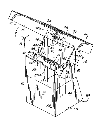
The stand 10 includes a tray 14 having a flat
bottom panel 16, a front border panel 18, a rear border
panel 20, and two side border panels 22, 24. The border
panels each extend perpendicularly of the bottom panel
16, and together form a rectangular border surrounding
the entire perimeter of bottom panel 16. The articles 12
are placed on bottom panel 16 and confined in the tray by
the border panels. Partition panels 26, 28 subdivide
the ir.rerior of the tray for sorting the articles.
Stand 10 also includes a base 30 erectable
from a collapsed to an erect condition. The tray 14 is
pivotably connected to the base 30 by means of a hinge
panel or flap 32 having one hinge section 34 fixedly
secured, e.g. by glueing or stapling, to the bottom tray
panel 16, and another hinge section 36 similarly fixedly
secured to the base 30. The hinge sections 34, 36 are
~2 ~ 3~
angularly movable in a circumferential direction about
hinge axis A-A which extends along a fold line of the
hinge 32. As described in greater detail below, the
tray 14 is pivotable upwardly, and is lifted manually
above the base (see FIG. 2), and is pivotable downwardly
and lowered onto the base (see FIG. 3).
As best shown in FIG. 3, the base 30 includes
a front panel 38 and a rear panel 40 lying substantially
1at against each other in the collapsed condition(FIG.l),
~nd movable away from each other in mutual parallelism
during erection of the base to the erect condition
(PIG. ~). The base 30 also includes side panels extend-
ing between the front and rear panels at opposite sides
of the stand. Each side panel includes a pair of side
panel portions 42, 44 and 46, 48. Each side panel por-
tion pair lies substantially flat against each other in
the collapsed condition, and are out-folded from each
other in a coplanar state during erection of the base.
In the erect condition, the coplanar side panel portions
42, 44 extend generally parallel to the coplanar side
panel portions 46, 48.
Front panel 38 is hinged to side panel portions
42, 46 along fold lines 50, 52. ~ear panel 40 is hinged
to side panel portions 44, 48 along fold lines 54, 56.
Side panel portions 42, 44 meet and are foldable about
upright fold line 58. Side panel portions 46, 48 meet
and are foldable about upright fold line 60. As best
shown in FIG. 5, the fold lines 58, 60 lie in a common
plane B-B. The front and rear panels are movable toward
and away from said common plane B-B with concomitant
folding of the side panels onto each other, and unfold-
ing of the side panels into respective coplanar states,
respectively.
A pair of support panels, each constituted of
a pair of support panel portions 62, 64 and 66, 68, are
hinged to side panel portions 42, 44 and 46, 48, respec-
tively (see FIG. 5). Support panel portions 62, 64 are
coplanar with support panel portions 66, 68, and lie in
the common plane B-B. Support panel portions 62, 64
are located further apart from support panel portions
66, 68 in the collapsed condition, and are moved closer
to support panel portions 66, 68 in the erect condition.
Slots 70 are formed through upper marginal
portions of support panel portions 62, 64. Slots 72
are formed through upper marginal portions of support
panel portions 66, 68. A circumferentially complete
elastomeric band 74, preferably a rubber band, has op-
posite arcuate ends frictionally received and maintained
in slots 70, 72. Band 74 is stretchable between a high-
tensioned stretched state in the collapsed condition
wherein the support panel portion pairs 62, 64 and
66, 68 are spaced apart, and a less-tensioned state in
~2 ~ 9~
the erect condition wherein the support panel portion
pairs are located closer together. The energy stored
in the stretched band 74 constantly urges the support
panel portion pairs together.
Hence, unless restrained by an outside holding
force, the band 74 serves as a biasing means operative
for urging the support panel portion pairs together
and, in turn, to unfold the side panel portion pairs
to their respective coplanar states wherein the side
panels are in mutual parallelism. In turn, the biasing
means moves the front and rear panels away from each
other until the erect condition of the base shown in
FIGs. 3 and 4 is obtained. The outside holding force
could be provided by non-illustrated clamping or similar
holding means. Alternatively, the base 30 can be pro-
vided with a transverse fold line or crease 76 which
divides the base into an upper part and a lower part.
By folding the upper flattened base above crease 76 onto
and into flat engagement with the lowered flattened part
of the base below crease 76 and, thereupon, by resting
the tray 14, preferably with the articles pre-packed
therein, against the juxtaposed upper and lower parts
of the stand, the weight of the tray, as well as the
weight of the articles packed therein, acting in the
direction of arrow C in FIG. 1, is sufficient to main-
tain the base in the illustrated compact storage position
--10--
~2~
shown in FIG. 1 without risk that the base 30 will auto-
matically pop open and erect itself under the influence
of the biasing means.
The pre-pack tray with the base folded flat
underneath the same is shipped in the orientation shown
in FIG. 1 to a display site. Once it is desired to erect
a display stand at the display site, it is merely neces-
sary to manually lift the tray 14 up above the folded
base 30. By removing the downwardly directed force act-
ing to maintain the base in the collapsed condition, the
base 30 is free to erect itself by unfolding and deploy-
ing the panels under the biasing action of the band 74
which acts in the directions of arrows D in FIG. 2.
~he base 30 having been fully erected, the tray 14 may now
be lowered in the direction of arrow E in FIG. 3 onto
the erected base. The tray is automatically centered
on the base. The tray cannot be mounted off-center or
laterally shifted on the base due, primarily, to the
hinge panel 32.
Each of the base panels has an upper edge or
support surface on which the tray is supported. Thus,
front panels 38, 40 have upper support surfaces 38a, 40a.
Side panel portions 42, 44, 46, 48 have upper support
surfaces 42a, 44a, 46a, 48a, respectively. A11 of the
aforementioned support surfaces bound a four-sided sup-
port on which the tray can be reliably supported from
--11--
_~L t~
below without tipping either in the front-to-back or
side-to-side directions. In addition, the support
panels have upper support surfaces 80, 82 which advan-
tageously may contact the bottom panel 16 of the tray
and help support the same across its middle.
For increased support, upper support surfaces
42a, 46a can be notched at 84, 86 in order to engage
the front border panel 18 at opp~site lateral end re-
gions thereof and to engage, at least in part, the bot-
tom paneL 16. Still further, not only is the back of
the tray held in position by hinge panel 32 and thereby
prevented from sliding downwardly or falling off the
base, but,also,the front of the tray is held in posi-
tion by a locking flap 88 of one piece with and extend-
ing above the upper support surface 38a of the front
panel 38. The locking flap 88 engages the front border
panel 18 and effectively iocks the tray in place, a
situation best shown in FIG. 4. Advantageously, the
upper support surfaces of the base are inclined relative
to the horizontal so that the tray itself is supported
on an incline. The angle of inclination of the tray is
advantageously chosen to provide maximum eye-catching
appeal for the articles on display.
To collapse the stand, one need only lift the
tray above the base, collapse the base along plane B-B
by stretching the band, folding the base about crease 76,
-12-
~2~ t~ .
and placing the tray back onto the folded base. The
collapsed stand can now be conveniently discarded or
re-packed as desired.
The tray itself, as well as the display stand,
may be constituted of cardboard or corrugated board.
It will be understood that each of the ele-
ments described above, or two or more together, also
may find a useful application in other types of construc-
tions differeing from the types described above.
While the invention has been illustrated and
described as embodied in a pre-pack display stand and
method of erection, it is not intended to be limited to
the details shown, since various modifications and struc-
tural changes may be made without departing in any way
from the spirit of the presen~ invention.
Without further analysis, the foregoing will so
fùlly reveal the gist of the present invention that others
can, by applying current knowledge, readily àdapt it for
various applications without omitting features that,
from the standpoint of prior art, fairly constitute
essential characteristics of the generic or specific
aspects of this invention and, therefore, such adaptations
should and are intended to ~e comprehended within the
meaning and range of equivalence of the following claims.
What is claimed as new and desired to be pro-
tected by 1etters Patent is set forth in the appended
claims.
-14-