Note: Descriptions are shown in the official language in which they were submitted.
~846~37
DU~ hESSURE POWERED A.tR VOLUME CONTROLLER
Background of the Invention
In the heating and cooling of relatively large buildings, a
number of problems are encountered. Building codes usually
require a predetermined minimum air flow to meet ventilation
requirements resulting in the supplying of conditioned air to
zones independent of their thermostatic requirements. One
result can be overcooling which, typically, eY~ists at the
start of a work d~y. Since thermostatic response would be
wrong for heating and the heating would not be fast enough at
the minimum flows required for ventilation purposes, a
temporary switchover of both the air supply and thermostatic
response is necessary. As the various terminals open and/or
throttle, the plenum static pressure changes which must also
be accounted for in the-operation of the controller in order
to maintain a stable operation.
Summary of the Invention
The present invention is directed to a controller which is
connected to a duct pressure powered air terminal unit. A
pressure drop is sensed in the terminal unit and is related
to a specific air flow in the unit. The sensed pressure drop
is communicated to the controller as two pressure signals.
The controller bleeds one pressure signal so as to control
the inflation of a bag or bellows and to thereby modulate the
terminal unit to maintain a constant volume air flow through
the unit as duct static pressure varies. The controller
bleeds the second pressure signal so as to maintain at least
a minimum flow through the unit. The amount of the constant
volume air flow and the minimum air flow are settable on the
controller and may be overrldden by a thermostatic input.
It is an object of this invention to provide a duct pressure
powered air volume controller.
1~84607
It is another object oE this invention to provide a control-
ler which is suitable for both constant volume and variable
air volume control.
It ls a further object of this invention to provi.de a con-
troller which is settable for both a constant volume air flow
and for a minimum air flow. These objects, and others as
will become apparent herei~Lafter, are accomplished by the
present invention.
Basically a differen~ial pressure is sensed in a terminal
Ulli~ and used to colltr~l the in~latlon of a bellows or bsg.
Control of th~ infla~ion of the bellows or bag is achieved by
controlllTIg the bleeding of one of the sensed pressures. The
bl~eding of the second o~le oE ~h~ sensed pressure~ ean be
used to produce a selected mlnimum flow through the terminal
unit.
According to a broad aspect the invention relates to a
duct pressure powered air volume controller comprising:
housing means having first, second, third and
fourth ports~
elongated movable means located within said housing
means and having a ~irst end which engages a first side of a
first diaphragm and a second end which engages a first side
of a second diaphragm~
a first chamber means formed in said housing means
and partially defined by a second side of said first
diaphragm;
a second chamber means formed in said housing means
and partially defined by a second side of said second
diaphragm;
spring means located in said second chamber means
and biasing ~aid second diaphragm against said second end of
said elongated movable me~ns;
iir~ fluid path m~ans connecting said first and
fo~rth ports via said first chamber means and having a 1rst
~' .
1~8~607
2(a)
ori~ice betweerl said flrst port and sald first chamber;
second fluid path means connecting said second port
w1 ~ n~ n wl~ n t ~ o /~n~ t) ~
coact~q with Haid elongated movable means to concrol the
r~ ance to flow frorn sald noz~le means;
third flui~ pa~h mean~ connecting ~ald ~hlr~ port
Wi~ll said second chamber tlleans; and
fourth fluid path means containing a second orifice
and connecting said second and third flow path means.
According to a further aspect the invention relates to an
air distribution system comprising: ~
an air terminal unit including a plenum divided
into high and low pressure areas having high and low pressure
pickup means, respectively, and inflatable bellows means for
controlling the flow of air from said plenum to a diffuser
for discharge into a zone;
bleed thermostat mesns;
a duct pressure powered air volume controller
including:
(a) housing means having a first port connected to
said low pressure pickup means, a second port connected to
said bellows means, a third port connected to said high
pres~ure pickup means ~nd~a fourth port connected to said
bleed thermostat means;
(b) elongated movable means located within said
housing means and having a first end which engages a first
side of a first diaphragm and a second end which éngages a
first 4ide of a second diaphragm;
(c) a first chamber means formed in said housing
mea.ns atld partially deined.by a second side of said first
dinphr~m;
. ' ~ ` "~!
1~8460~
2(~)
(d) a second chamber means formed in said housing
means and partially defined by a ~econd side of said second
diaphragm;
(e) spring mean~ located in said second chamber
mean~ and biaslng said second diaphragm ag~inst s~id second
end o s~id elongated movabl~ means;
(f) first flui~ path me~n~ connecting s~id first
l~l n ~ r t ~ ) r ~ ~ v l ~ rl i ~ r ~ r ~ c ll ~l ml) ~ r ~nt3 Ll n ~ v l. n ~ n
first orifice between said first port and sai~ first chamber
whereby said irst chamber i9 connected to said low pressure
pickup means and to ambient via said bleed thermostat means;
(g) second fluid path means connecting said second
por~ with nozzle.means which discharges to ambient and which
coacts with said elongated movable means to control the
resistance to 10w from said nozzle means which coacts with
said elongated movable means to control the resistance to
flow from said nozzle means and thereby the inflation and
deflation of said bellows me~ns;
(h) third fluid path means connecting said third
por~ with said chamber means whereby said second chamber is
connected to said high pressure pick~p means; and
(i) fourth 1uid path means containing a second
orifice and connecting said second and third flow path means
whereby said high pre~sure pickup means can be connected to
~aid bellows means.
Brief Descrlption of the Drawings
For a fuller understanding of the presen~ inventlon, refer-
ence should now be made to the following detalled description
thereof taken in conjunction with the accompanying drawings
wherein:
Figure 1 is a sectional view of the alr volume controller of
the present invention;
''1
.'.. ~`,~ .
~84607
2(c)
Figure 2 i8 a sectlonal view corresponding to Figure 1 but
showing only the housing of the air volume controller;
Figure 3 is a sectional view of the low side plug;
Figure 4 is ~ sectlonal view oi the high side plug;
Figure 5 is a partially sectioned view of the high side plug
and cam assembly; and
1~84~7
Figure 6 is a schematic represent:ation of a control system
using the air volume controller of the present invention in a
heating-cooling control with a variable air volume thermal
changeover.
Description of the Preferred Embodiment
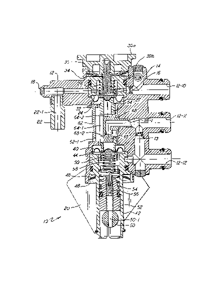
In the Figures, the numeral 10 generally designates an air
volume controller having a housing 12. Referring specifical-
ly to Figure 2, housing 12 has a bore therein serially
defined by bores 12-l to 12-7. Shoulder 12-8 is formed
between bores 12-2 and 12-3 while shoulder 12-9 is formed
between bores 12-5 and 12-~. Bore 12-10 defines the low
pressure inlet port and transversely intersects bore 12-2.
Bore 12-11 defines the bellows port and terminates in bore
12-4. Bore 12-12 defines the high pressure inlet port and
terminates in bore 12-~. Bores 12-11 and 12-12 are connected
by bore 12-13 which contains bellows orifice 13. Bore 12-14
terminates in bore 1 -10 and has a threaded opening 12-15 for
receiving threaded adjusting screw 14 which provides an
adjustable bleed to the atmosphere.
Referring now to Figure 1, plug 18 seals one end of bore
12-10. Orifice 16 is located in bore 12-10 between bores
12-2 and 12-14. Pipe 22 is received in bore 12-16 and defines
a thermostat port. Low side diaphragm 24 is peripherally
sèaled between shoulder 12-8 and low side plug 30. Referring
now to Figure 3, plug 30 is made up of upper portion 30a and
lower portion 30b. Lower portion 30b has an annular recess
30-1 formed therein. Spaced, diametrically located bores
30-2 and 3 extènd radially outward from annular recess 30-1
to annular recess 30-4 so as to form a continuous p~ssage
with bore 12-10 in the assembled controller 10. Recess 30-5
is formed in the surface of lower portion 30b periyherally
engagitlg diaphragm 24 to thereby define with diaphragm 24 a
low pressure chamber 32. Threaded bore 30-6 is formed in
1~84607
lower portion 30_ and threadably receives minimum flow
adjusting scr~w 30~7 which serves to connect upper portion
30a and lower portion 30_ together as a unit. Screw 30-7 is
press fit into bore 30-9 of upper portion 30a so as to be
integral th~rewith. Upper portion 30a defines minimum flow
adjusting knob 30-8 which provides for field ~djusting the
position of lower portion 30_ to thereby regulate the spring
bias applied by low side spring 26 against low side spring
cup 27 and to limit the movement of element 64 in the direc-
tion of plug 30. Plug 30 is held in bore 12-2 in engagement
with ~he periphery of diaphragm 24 by the biasing force of
wavy spring or washer 34 which is, in turn, held in place by
spring retainer 36.
~igh side diaphragm 40 is peripherally sealed between shoul-
der 12-9 and high side plug 42. As best shown in Figure 4,
plug 42 has a bore therein serially defined by bores 42-1 to
42-3. Shoulder 42-4 is formed between bores 42-1 and 42-2.
Bore 42-3 terminates in recess 42-5 which ls located opposite
diaphragm 40 in the assembled controller to define therewith
high pressure chamber 44. Diametral bore 42-6 provides fluid
communication between annular groove 42-7 and bore 42-3.
Plug 42 i8 held in bore 12-6 in engagement with the periphery
of diaphragm 40 by the biasing force of wavy spring or washer
46 which is, in turn, held in place by spring retainer 48.
Referring now to Figures 1, 4 and 5, cam 50 is located in
opening 42-8 which is transverse to bore 42-1. Opening 42-8
is made up of two intersecting circular openings 42-9 and
42-10. Circular opening 42-9 is larger to receive the cam
member 50-2 of cam 50. After cam 50 is inserted in opening
42-9 it is then pushed down so that the shaft 50-3 is forced
into and locked in the smaller opening 42-8. Cam member 50-2
has an axial bore 50-1 and adjustably positions cam follower
52 against the bias of cam follower spring 54 which seats on
shoulder 42-4. Threaded axial bore 52-1 is formed in cam
12846(~7
follower 52 and threadably receives spring adjuster 56.
Spring adjuster 56 has an axial recess 56-1 which receives
one end of spring 58 while the other end of spring 5~ is
received in high side spring cup 60 and forces spring cup 60
into engage~lent with diaphragm 40. Indicator 20 is secured
to cam 50 and i9 rotated to a desired position indicated by
indicia (not illustrated) to properly position the cam member
50-2 in accordance with the selected position.
Bore 12-4 is vented to the atmosphere via relieved portion
62-1 of removable cover 62. Tubular element 64 is located
within bore 12-4 and is engaged at its respective ends by
diaphragms 24 and 40. Transverse opening 64-1 i8 formed in
ele~ent 64 and intersects axial bore 64-2. Plug 66 is press
fit into the lower portion of bore 64-2 of elemént 64.
Nozzle 68 i8 received in bore 12-11 and extends into bore
12-4. Bore 68-1 in nozzle 68 forms a continuous flow path
with bore 12-11 and terminates in port 68-2 located in
opening 64-l. The relative positions of port 68-2 and plug
66 d~fines a gap which dictates the resistance to flow from
port 68-2 and the position of plug 66 is changed with tnove-
ment of tubular element 64.
With air volume controller 10 assembled as shown in Figure 1
and with cam 50 in the position shown in Figures 1 and 5,
bores 50-1 and 52-1 provide access to spring adjuster 56
which may then be adjusted by a screw driver, allen wrench or
the like extending through bores 50-1 and 52-1.
By thus threadably positioning spring adjuster 56, the
tension of spring 58 can be factory adjusted to set the
balance point by calibration to a specific point. The air
volume controller 10 can then be connected to a terminal as
shown in Figure 6. Nozzle plate 74 divides plenum 72 into
high and low pressure areas 72a and _, respectively. High
pressure pickup 76 extends through nozzle plate 74 into high
84607
pressure ar~a 72a and is connected via line 77 to the high
pressure inlet port defined by bore 12-12. Low pressure
pickup 78 is located within low pressure area 72b and is
connected via line 79 to the low pressure inlet port defined
by bore 12-lO. Bellows 80 and retainer 82 coact to define a
sealed chamber 81 whereby bellows 80 is positioned with
respect to plenum outlet 84 responsive to the pressure in the
chamber 81 for controlling the flow of air to diffuser 86.
Chamber 81 is connected via line 85 to the bellows port
defined by bore 12-11.
Depending upon the connection of pipe 22 whose bore 22-1
defines the thermostat port, the air volume controller 10 and
terminal 70 can be operated in several modes. If the thermo-
stat port is closed, as by a plug, a constant volume control
will result while if the thermostat port is connected to a
cooling only bleed thermostat a variable air volume control
will be obtained. If, as illustrated in Figure 6, the
thermostat port is connected to a heating/cooling bleed
thermostat 90 through a changeover valve 88, then a
heating/cooling control with variable air volume thermal
changeover is obtained. If the Figure 6 arrangement is
modified by replacing heating/cooling thermostat 90 with a
cooling only bleed thermostat then a variable air volume
control with warmup is obtained, and if a thermal warm up
control is added, a variable air volume control with warm up
wlll result.
Changeov~r valve 88 is a thermally actuated three-way valve
which is an assembly of two two-way valves, 88-1 and 2, and
directs the bleed signal from controller 10 to the proper
portion of heating/cooling thermostat 90. When the tempera-
ture in plenum 72 is above the valve setpoints, the signal of
controller lO will be transmitted to the heating bimetal of
the thermostat 90. Likewise when the temperature in plenum
72 drops below the setpoint, that signal will be transmitted
~'~84607
to the coollng bimetal of the thermostat 90. For example,
~he heating bimetal will be in thermal control when the
plenum air temperature is above 75F and the cooling bimetal
will be in thermal control when the plenum alr temperature i8
below 70F. The changeover valve 88 is necessary in cooling/
heating applications to prevent under-cooling or
over-heatin~. For exanlple, with no changeover valves and
with cold air being supplied, a drop in the temperature of
the controlled space because of an outside temperature drop,
for example, causes the cooling thermostat to close. The
heating thermostat, however, sensing a need for heating would
call for "heating" airflow and would cause cool air to flow
into the zone further cooling it. The changeover 88 keeps
the proper thermostat in control based upon the supply
temperature.
The air volume controller 10 is thus fed with high pressure
air, PHl, via line 77 and low pressure air, PLo~ via line 79.
The high pressure air communicates via bore 12-12, groove
42-7, bore 42-6 and bore 42-3 with high pressure chamber 44
where it acts against the lower side of diaphragm 40, as
illustrated. Spring 58 also acts through spring cup 60
against the lower side of diaphragm 40. The biasing force
supplied by spring 58 i~ a result of the position of spring
58 due to spring adjustment 56 and the position of cam
follower 52 due to the pOSitiOII of cam member 50-2. The
upper side of diaphragm 40 engages tubular element 64.
The balance point is set by increasing or decreasing the
compression of spring 58. This spring is first set at
calibratioll to a specific point, ~hen at installation by
adjusting cam 50. Cam 50 rotates and cam member 50-2 raises
or lowers cam follower 52 which repositions spring 58.
Rotating cam 50 to raise the cam follower results in a lower
airflow setpoint because tubular element 64 and thereby plug
66 is pressed toward port 68-2 decreasing the gap and thereby
1~34607
the exhaust and thus increasing the bellows inflation.
Lowering the cam follower 52 results in an increased airflow
setpoint.
The low pressure air commlunicates via bore 12-10, orifice 16,
annular recess 30-4, bores 30-2 and 3 and annular recess 30-1
with low préssure chamber 32 where it acts against the upper
side of diaphragm 24, as illustrated. The lower side of
diaphragm 24 engages tubular element 64 which is thus subject
to a differential pressure which tend~ to move tubular
element 64 accordingly. The pressure in low pressure chamber
32 is regulated by bleeding to atmosphere through bore 12-14
under the control of threaded adjusting screw 14 as well as
subject to bleeding of air supplied via bore 12-16 to the
bleed thermostat 90. The pressure in high pressure chamber
44 is communicated via bore 12-13 and orifice 13 with bore
12-11 which co~municates via line 85 wlth chamber 81 for
controlling the inflation and deflation of bellows 80.
Additionally, bore 12-11 communicates with the atmosphère via
bore 68-1 and port 68-2. The pressure differential acting
across tubular element 64 causes its movement and that of the
plug 66 which is carried by element 64. Plug 66 is located
beneath port 68-2 which acts as a bleed nozzle which is
thereby modulated responsive to the position of plug 66. The
closer plug 66 is to port 68-2, the smaller will be the
actual exhaust porting resulting in a greater flow resistance
and a higher pressure in chamber 81 causing a closing of
plenum outlet 84. As plug 66 moves away from port 68-2, the
exhaust porting is increased resulting in a decrease in
pressure ln chamber 81 and an opening of plenum outlet 84.
Orifice 13 acts as a balancing orifice for thé coaction of
plug 66 and port 68-2. The balancing of forces acting on
tubular element 64 through diaphragms 24 and 40 at a control
point coincident with the differential pressure across the
nozzle plate 74 sets the relative positiorls of plug 66 and
~4607
port 68-2 and thus the exhaust through port 68-2 and the
pres~ure in chamber 81 which results in an air flow through
terminal 70 consistent with the setpoint. A rise in pressure
in high pressure plen~m area 72cl is thus communicated to bore
12-12 and ultimately to high pressure chamber 44 where it
produces an increased differential across tubular element 64.
This increased differential tencls to move element 64 upwards
callsing plug 66 to close port 68-2 thereby raising the
pressure in chamber 81 causing bellows 80 to inflate and move
toward closing plenum outlet 84 until a pressure balance
across elemerlt 64 is again achieved. This action maintains a
constant airflow delivery through terminal 70. Similarly, a
decrease in the pressure in high pressure plenum area 72a
will result in a decrease in differential pressure across
element 64 causing element 64 to move again and open port
6~-2.
When the thermostat port defined by pipe 22 is closed either
by capping or by the applied thermostat bleed port being
closed thermally, full low pressure acts on diaphragm 24. As
the thermostat port defined by pipe 22 or the corresponding
bleed thermostat opens, the pressure in chamber 32 is bled
off allowing the effective differential pressure on element
64 to increase causing it to move toward port 68-2 thereby
decreasing the exhaust flow and causing an increase in the
pres~ure in chamber 81 which inflates bellows 80 and decreas-
es the delivered unit airflow. As the thermostat port
defined by pipe 22 approaches full open, the terminal 70 will
continue to deliver decreased airflow. Minimum airflow
adjusting screw 30-7 is positioned to restrict the movement
of element 64 to thereby prevent plug 66 from completely
closing port 68-2 and allowing air to bleed from chamber 81
so as to prevent terminal 70 from being completely shut off.
Although a preferred embodiment of the present invention has
been illustrated and described, other changes will occur to
~8~6(37
those skilled in the art. It is therefore intended that the
scope of the present invention is to be limited only by the
scope of the appended claims.