Note: Descriptions are shown in the official language in which they were submitted.
608
BACKGROUND OF THE INVENTION
Field of the Invention:
This invention relates to improved flow seats for poppet
valve assemblies, and particularly to flow seats having port exit
constructions exhibiting reduced flow losses.
Description of the Prior Art:
Valve assemblies using poppets movable alternately, into,
and out of, engagement with the exit of a fluid port for control-
ling fluid~flow are well known in the art. See e.q. U.S.
4,228,820. Examples of the use of such poppet valve assemblies
are in gas compressors where, in larger models, the poppet valve
assembly can include a number of separate poppet valves operating
in parallel in the same valve assembly.
As in other types of check valves, poppet valve assemblies
lj can introduce unwanted, unrecoverable pressure drops along the
fluid path which can result in undesireable flow throttling and
reduce compressor overall efficiency. These unrecoverable pres-
sure drops stem not only from the frictional losses in the compo-
nent but also from the form losses caused by abrupt expansions or
2~ contractions in the component cross-sectional flow area. Eddy
formations and other hydrodynamic processes at these flow area
changes can result in the unwanted conversion of kinetic energy
of the flowing fluid to heat energy which cannot be recovered as
PV energy in a diffuser and thus represent a loss in compressor
~5 efficiency.
r
--1 ~
q~
~ ~84608
It is a fundamental object of the present invention to re-
duce the energy losses at the port exit region of the flow seat.
Additional objects and advantages of the invention will be set
forth in part in the description which follows, and in part will
be obvious from the description, or may be learned by practice of
the invention.
SUMMARY OF T~IE I NVENT I ON
In accordance with the present invention as embodied and
broadly described herein, the improved poppet valve seat assembly
includes a seat member having a surface with at least one port
having an exit forming an edge with the adjacent portion of the
surface, the seat assembly for use with a poppet movable into,
and out of, engagement with the seat member for sealing, and
unsealing, the port exit, respectively, and means for reducing
the pressure losses incurred by fluid flowing out of the port
exit past the port exit edge. Specifically, the loss reducing
means includes a chamfer formed at the edge of the port exit and
a counter-bore formed in the port exit edge upstream of the cham-
fer with respect to the flow direction through the port.
~ Preferably, the counter-bore has a characteristic depth "D"
measured axially from the chamfer and a characteristic width "W"
measured radially from the wall of the port, and the ratio D/W is
between about 2:1 and about 3:1. It is also preferred that the
angle of the chamfer with respect to the seat member surface is
about 30 degrees.
-
~ -2-
,,, ,i",..................... .. ..
~84608
And it is still further preferred that a poppet valve assem-
bly for gas compressors using the aforementioned improved poppet
valve seat assembly additionally includes a poppet guard member
disposed adjacent the seat member surface, and a plurality of
poppets each mounted in the guard member for movement into and
out of engagement with a respective port, each of the poppets
having a conical sealing face.
The accompanying drawings which are incorporated in and con-
stitute a part of this specification, illustrate one embodiment
1~ of the invention and, together with the description, serve to ex-
plain the principles of the invention.
BRIEF DESCRIPTION 0F THE DRAWING
Fig. 1 is a schematic, cut away perspective view of the im-
proved poppet valve assembly made in accordance with the present
invention;
Fig. 2 is a plan view of the seating member component of the
poppet valve assembly shown in Fig. l;
Fig. 3 is the bottom view of the seating member component of
the poppet valve assembly shown in Fig. l;
Fig. 4 is a sectional view taken at the lines 4 of the
seating member component shown in Fig. 3;
Fig. 5 is a sectional view of a variation of the embodiment
shown in Fig. l; and
R -3-
, . . .
iO8
Fig. 6 is a detail through the port exit region of the
poppet value assembly in Fig. 5.
DESCRIPTION OF THE PREFERRED EMBODIMENT
Reference will now be made to a preferred embodiment of the
present invention, examples of which are illustrated in the
drawings.
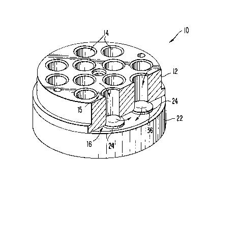
A poppet valve assembly made in accordance with the present
invention is shown schematically in Fig. 1 and is designated gen-
erally by the numeral 10. Poppet valve assembly 10 can be advan-
l~ tageously used in a gas compressor, but the present invention is
not restricted to apparatus for use in gas compressors or for use
with a gas-type fluid. Poppet valve assembly 10 includes seating
member 12 having a plurality of cylindrical, parallel through-
ports 14 distributed across the member. As best seen in Figs. 2
and 3, each of ports 14 includes an inlet portion 15 and an exit
portion 16. Specifically, exit portions 16 form edge areas 18
with the immediately adjacent parts of seating member lower sur-
face 20.
Poppet valve assembly 10 also includes poppet guard member
~ .22 disposed adjacent to surface 20 of seat member 12. A plurali-
ty of individual poppets 24 are carried by guard member 22 to be
movable into and out of engagement with respective ports 14 for
alternately sealing and unsealing port exits 16. A plurality of
through-bores (not shown in Fig. 1) are provided in guard member
;, -4-
.R
,~:",.. ", . ,: , . . . .
34608
22 to channel fluid exiting ports 14 past poppets 24 and guard
member 22. See Fig. 5 showing a c:ut away of guard member 22'
where through-bores 26' are depicted.
Referring again to Fig. 1, the intended flow path past
poppet valve assembly 12 when poppets 24 are in the retracted,
unsealing position (they are shown in the sealing position in
Fig. 1) is indicated generally by the double arrows. Although
the embodiment depicted in Fig. 1 shows a total of 12 ports dis-
tributed in a particular fashion, the present invention is not
restricted to this number or to the particular arangement shown.
Fig. 5 depicts a variation having a larger number of ports 14'.
Also, ports 14 may be of different cross sectional shape, and it
is understood that the shape of the sealing face of poppet mem-
bers 14 will correspond to the shape of the port exit. Simi-
larly, various means can be utilized for insuring alignment of
the poppets 24 with a corresponding port exit 16. In the embodi-
ment shown in Figs. 1-4, a pair of dowel pins 28 (see Fig. 3) are
provided in sealing member 12 to engage corresponding pilot holes
(not shown) in guard member 22 to provide such alignment.
In accordance with the present invention, means are provided
for reducing energy losses incurred by fluid flowing out of the
port exits. Specifically, the loss reducing means includes a
chamfer formed in each of the port exit edges. As embodied here-
in and as best seen in Fig. 4, edge 18 has chamfer portion 30
--5--
~84~(~8
formed at an angle alpha with the seating member surface 20.
Preferably, angle alpha is about 30 degrees.
Also in accordance with the present invention, the loss re-
ducing means includes a counter-bore formed in the port exit edge
immediately upstream of the chamfer in respect to the fluid flow
direction. As embodied herein and with continued reference to
Fig. 4, counter bore 32 is formed in edge 18 upstream and immedi-
ately adjacent chamfer 30 with respect to the fluid flow direc-
tion in port 14 as designated by the double arrows. Preferably,
counter-bore 32 is of the sharp-corner type with the internal
corner 34 having a maximum radius of less than about 1/64 inch.
These same features are depicted in Fig. 6 in an enlarged view of
the port exit edge of the Fig. 5 poppet value assembly, with cor-
responding ports being designed with like reference numerals but
i5 with a prime superscript.
It has been found that the degree to which the energy losses
can be reduced by the combination of the chamfer and upstream
counter-bore in the present invention is strongly dependent upon
the ratio of the counter-bore characteristic depth "D" divided by
2~ the counter-bore characteristic width "W". As used herein and as
best shown in Fig. 6, the counter-bore characteristic depth "D"
is defined as the axial distance along port 14' occupied by
counter-bore 32' exclusive of the depth of chamfer 30'. The
characteristic counter-bore width "W" is defined as the radial
distance measured from the wall of port 14'.
-6-
4608
It is highly preferred that the dimensions of the counter-
bore be such that the D/W ratio lie between about 2:1 and about
3:1. Test results have shown that a more than 24% improvement
(decrease) in the port exit resistance factor can be achieved
using counter-bores having a D/W ratio in the 2:1 - 3:1 range,
compared to a slightly less than 7% resistance factor decrease
for a counter-bore with a D/W ratio of about 1:1.
An example of the improved poppet valve assembly depicted in
the figures was constructed using 1141 steel for the seating mem-
' ber 12 and guard member 22. Poppets 24 were injection molded
glass-filled nylon and were slidingly mounted in guard member 22
biased to the sealing position with variable rate 17-7 PH steel~3
springs (not shown in Fig. 1, but see springs 38 in the Fig. ~ 5~5 1
embodiment). The nominal diameter of the individual ports 14 was
i5 1 and 1/16 inch, and a 30 degree chamfer was used extending to a
maximum diameter of about 1.28 inches (see representation of the
maximum chamfer diameter d in Fig. 3). Each port exit had a
counter-bore with a characteristic depth D of about 1/16 inch and
a characteristic width W of about 1/32 inch, yielding a D/W ratio
2~ of about 2:1. Also, the poppets each had conical sealing faces
(see faces 36 in Fig. 1) with a 30 degree slope to provide good
conformity (and thus sealing) with chamfer 30 on port exit edge
18.
-7-
- . .,i . ..~.,,
34608
It will be apparent to those skilled in the art that various
modifications and variations can be made in the poppet valve
assemblies of the present invention. Thus, it is intended that
the present invention cover the modifications and variations of
S this invention provided they come within the scope of the
appended claims and their equivalents.
-8-
. ~,